HYDAC压力表参数调整 (2)
- 格式:xlsx
- 大小:1.29 MB
- 文档页数:6

压力表校准方法
1.目的:确保压力表精度
2.范围:适用压力表精度,外观校准
3.调校步骤(标准表比较法)
3.1仪表的安装与排汽
将标准表与被校表分别安装于同一个管上,检查两个表上显示的值是否一致。
排汽方法如下:新安装、拆装的压力表,须进行排汽工作,关闭气路阀门,先逆时针转动手柄抽气,再顺时针转动手柄排气。
多次反复进行并随时观察油面排气情况,直至无气泡排出为止。
3.2检查零点
应在没有压力情况下检查压力表是否归零点
3.3加压校验
打开气阀,对比标准表和被校准表显示的压力值是否一致。

压力表校准方案一、校准目的。
咱校准压力表呢,就是要让这表能准确地告诉咱压力的情况,就像让一个爱乱报数的家伙变得诚实可靠一样。
这样在各种需要知道压力数值的地方,比如工厂的设备、汽车的发动机啥的,它才能给出靠谱的信息,不至于让咱做出错误的判断,导致机器罢工或者更糟糕的情况。
二、校准依据。
这校准可不能瞎搞,得有依据。
一般呢,就是按照国家或者行业相关的标准来,这些标准就像是压力表校准的“宪法”,规定了怎么测、误差范围是多少之类的条条框框。
比如说,[具体标准名称]这个标准就详细地说明了压力表校准的各种要求,咱们就得按照这个来,让校准结果有说服力。
三、校准设备。
1. 标准压力表。
这可是校准的关键“裁判”。
它得比咱们要校准的压力表精度高好多才行,就像专业运动员和业余爱好者的区别。
一般来说,精度等级要比被校表高[X]级,这样才能准确地判断被校表的对错。
2. 压力源。
这就是给压力表提供压力的东西,就像给运动员提供比赛场地一样。
压力源得能够稳定地输出不同的压力值,从低压到高压都得行,这样才能全面地校准压力表。
比如说,[某种压力源设备名称]就挺不错的,它能输出[压力范围]的压力,而且压力波动很小,很适合用来校准。
3. 连接管路和接头。
这些东西就像把各个设备连接起来的桥梁。
要选择合适的管路和接头,保证在传输压力的过程中不会有泄漏,不然压力都跑了,还怎么校准呢?一般来说,要根据压力表的接口尺寸和压力范围来选择合适的管路和接头,材质也要耐用,像不锈钢的就挺好。
四、校准环境。
1. 温度和湿度。
校准的时候,环境的温度和湿度也很重要。
温度不能忽冷忽热,湿度也不能太湿或者太干,不然可能会影响压力表的准确性。
一般来说,温度保持在[温度范围],湿度在[湿度范围]比较合适,就像给压力表创造一个舒适的“家”一样。
如果环境条件不符合要求,可能会让校准结果出现偏差,就像人在不舒服的环境里干活容易出错一样。
2. 振动和电磁干扰。
还要避免振动和电磁干扰。

Flow Control ValvesDRV & DRVP Series (see page 47)Check ValvesRV & RVP Series (see page 53)Needle ValvesDV, DVE & DVP Series (see page 43)Pressure Compensated Flow Control ValvesSRVR Series (see page 51)Stainless Steel Flow Control ValvesDV, DRV & RV Series(see page 55)OverviewProduct Features• Phosphate coated steel valve body • FPM (Fluoroelastomer) seals• Slotted control spindle for precise and linear flow adjustments • Exclusive safety spindle design• Color coded spindle for accurate flow control•Guided poppets for smoother, chatter free operationAvailable Options• Panel mounting kit• 25 and 65 PSI cracking pressure springs (7 psi standard)• Zinc Plated Body. Consult HYDAC for price and deliveryIntroductionOur complete line of flow control valves are designed and manufactured by our ISO 9001 certified FLUTEC Division.Description• T he HYDAC family of flow control valves permit safe, simple and repeatable control of hydraulic fluids at operating pressures to 5000 psi.• T he standard slotted control spindle allows for a wide range of infinitely variable flow adjustments with excellent flow characteristics.• P recise adjustment of flow is achieved by a micrometer style adjustment knob featuring a color coded flow indicator for accurate, easy-to read visual flow reference.• D esign modifications and special materials are available for corrosive fluids such as phosphate ester, acids and caustics.Valve DesignHYDAC flow control valves can be adjusted easily and precisely by means of the control knob. Increasing the number of turns from the fully closed position provides a steady increase of the flow rate. The colored scale permits accurate repetition of settings and the colored triangle on the rising spindle provides a visual indication of the increasing cross section of the flow area. A set screw on the side locks the knob at the desired setting.HYDAC flow control valves include a unique safety spindle design feature. As the valve spindle is turned counter-clockwise, the spindle shoulder will engage the safety screw limiting the travel of thespindle. The hardened, high-strength steel safety screw is sealed in position to discourage tampering.Flow Control Valve Design Features and OptionsGuided PoppetA BDV, DVE, & DVP SeriesNeedle ValvesModel CodeDV - 06 - 01 .X / 5 - S - MNeedle Valve DV = Inline Mounting DVP = Manifold Mounting DVE = Cartridge ValveNominal Sizes DV & DVP SAE (DV only) NPT F (DV Only) BSPP (DV Only)Nom. Size Tube Size Thread Size Pipe Size Pipe OD Thread Size 06 = 1/8” 0.405” G1/8 08 = -4 7/16-20 UNF 1/4” 0.540” G1/4 10 = -6 9/16-18 UNF 3/8” 0.675” G3/8 12 = -8 3/4-16 UNF 1/2” 0.840” G1/2 16 = -12 1-1/16-12 UN 3/4” 1.050” G3/4 20 = -16 1-5/16-12 UN 1” 1.315” G1 25 = -20 1-5/8-12 UN 1-1/4” 1.660” G1 1/4 30 = -24 1-7/8-12 UN 1-1/2” 1.900G1 1/2DVENom Size SAE CavityBSPP Cavity 08 = 3/4-16 UNF G1/2 10 = 7/8-14 UNF G1/2 12 = 1-1/16-12 UN G3/4 16 =1-5/16-12 UNG1Housing Material 01 = Carbon Steel Modification NumberPort Configuration (omit) = DVP Only 5 = NPTF - ANSI B1.20.3 12 = SAE - SAEJ1926 Ports with ISO 725 Threads and O-Ring Sealing 0 = BSPP to DIN 3852, Part 2-X Supplementary Details S = Panel Mounting Kit (not available in sizes 20, 25, 30)Model Codes containing selections listed in RED are non-standard items – Minimum quantities will apply – Contact HYDAC for information and availabilityNot all combinations are availableSpecifications• 5000 psi operating Pressure • 8 Sizes, 1/8” - 1-1/2”• S AE O-Ring, NPT or BSPP Threaded Connections; Manifold Mounting; and Cartridge Type • Flows to 80 gpm• Carbon steel housing• FPM (Fluoroelastomer) O-Rings (standard)• Color coded spindle for accurate flow control • Provision for panel mounting • Unique safety spindle design• Temperature Range: -4˚ to 212˚F at full pressureHydraulic SymbolDV SeriesInline Mounting DVP SeriesManifold MountingDVE Series Cartridge Valve80604020100∆p(bar)Q (l/min)Size 0680604020100∆p(bar)Q (l/min)Size 12∆p(bar)Q (l/min)Size 10∆p(bar)Q (l/min)Size 20, 25, 30∆p(bar)Q (l/min)Size 08∆p(bar)Q (l/min)Size 16Q (l/min)∆p(bar)Q (l/min)Size 124030201050∆p(bar)4030201050∆p(bar)Q (l/min)Size 104030201050∆p(bar)Q (l/min)Size 16Pressure Drop curves were established by using mineral oil with kinematic viscosity 165 SUS at 112°F / 50°CPressure Drop CurvesDV, DVP, DRV, DRVP SeriesFlow Direction: A to B / Throttled FlowDVE Cartridge Flow Control ValvesFlow Direction: A to B / Throttled Flow1) Note: Pg style thread per DIN 40430Dimensions are for general information only, all critical dimensions should be verified by requesting a certified print.Dimensions are in inches/(mm) and lbs./(kg.)*Dependent upon valve and seal materials selected.DimensionsDV Series Inline Needle ValveKnob for Sizes 20-40for wrench1) Only 4 mounting holes are used on sizes 06, 08, 10, and 122) Pg Style Thread per DIN 40430Note: Contact factory for certified drawing of cartridge valve cavity.Dimensions are for general information only, all critical dimensions should be verified by requesting a certified print.Dimensions are in inches/(mm) and lbs./(kg.)DimensionsA BModel CodeDRV - 06 - 01 . X / 5 - 25 - S-MFlow Control Valve DRV = Inline Mounting DRVP = Manifold Mounting Nominal Sizes Nominal Size SAE (DRV only) NPT F (DRV Only) BSPP (DRV Only)(DRV + DRVP) Tube Size Thread Size Pipe Size Pipe OD Thread Size 06 = -2 5/16-24 UNF 1/8” 0.405” G1/8 08 = -4 7/16-20 UNF 1/4” 0.540” G1/4 10 = -6 9/16-18 UNF 3/8” 0.675” G3/8 12 = -8 3/4-16 UNF 1/2” 0.840” G1/2 16 = -12 1-1/16-12 UN 3/4” 1.050” G3/4 20 = -16 1-5/16-12 UN 1” 1.315” G1 25 = -20 1-5/8-12 UN 1-1/4” 1.660” G1 1/4 30 =-24 1-7/8-12 UN 1-1/2” 1.900” G1 1/2Housing Material01 = Carbon Steel Modification NumberPort Configuration(omit) = DRVP only 0 = BSPP to DIN 3852, Part 2 -X 5 = NPTF (ANSI B1.20.3) 12 = SAE - SAEJ1926 Ports with ISO 725 Threads and O-Ring Sealing Cracking Pressure(omit) = 7 PSI standard 25 = 25 PSI optional 65 = 65 PSI optionalSupplementary Details S = Panel Mounting Kit (not available in sizes 20, 25, 30)Model Codes containing selections listed in RED are non-standard items – Minimum quantities will apply – Contact HYDAC for information and availabilityNot all combinations are availableSpecifications• 5000 psi operating pressure • 8 sizes, 1/8” - 1-1/2”• N PTF or SAE O-Ring threaded connections, or manifold mounting • Flows to 80 GPM • Carbon steel housing• FPM (Fluoroelastomer) O-Rings (standard)• Color coded spindle for accurate flow control • Provision for panel mounting • Unique safety spindle design• Temperature Range: -4° to 212°F at full pressureHydraulic SymbolDRV & DRVP SeriesFlow Control ValvesDRV Series Inline MountingDRVP SeriesManifold Mounting18161420∆p (b a r )121086420Q (l/min)Size 06∆p (b a r )Q (l/min)Size 12∆p (b a r )Q (l/min)Size 10∆p (b ar )Q (l/min)Size 20, 25, 304030201050∆p (b a r )Q (l/min)Size 08∆p (b a r )Q (l/min)Size 16∆p (b a r )40302010500∆p (b a r )DRV-06-01.X to DRV-16-01.XQ (L/min)Pressure Drop curves were established by using mineral oil with kinematic viscosity 335 SUS at 86°F / 30°CFlow Direction: B to A / Free Flow Through Check ValvePressure Drop CurvesFlow Direction: A to B / Throttled Flow1) Pg style thread per DIN 40430Dimensions are for general information only, all critical dimensions should be verified by requesting a certified print.Dimensions are in inches/(mm) and lbs./(kg.)Dimensions DRV Series1) Only 4 mounting holes are used on sizes 06, 08, 10, & 122) Pg style thread per DIN 40430Dimensions are for general information only, all critical dimensions should be verified by requesting a certified print.Dimensions are in inches/(mm) and lbs./(kg.)Dimensions DRVP SeriesModel CodeSRVR - 08 - 01 .X / 5 - SPressure Compensated Flow Control ValveSRVR = Flow Control Valve (with internal check valve)Nominal Size NPTF OnlyPipe Size Pipe OD 08 = 1/4” 0.540” 10 = 3/8” 0.675” 12 = 1/2” 0.840” 16 =3/4” 1.050”Housing Material01 = Carbon Steel Modification NumberPort Configuration 0 =BSPP to DIN 3852, Part 2 -X 5 = NPTF (ANSI B1.20.3)Supplementary Details S = Panel Mounting KitModel Codes containing selections listed in RED are non-standard items – Minimum quantities will apply – Contact HYDAC for information and availabilityNot all combinations are availableSpecifications• 4 sizes, 1/4” - 3/4”• W orking Pressure:Inlet: 102 psi min. / 3045 psi max. Outlet: 0 psi min. / 2944 psi max.• Flows to 24 gpm • NPTF Connections • Carbon Steel Housing• FPM (Fluoroelastomer) O-Rings (standard)• Color coded spindle for accurate flow control • Provision for panel mounting • Unique safety spindle design• Temperature Range: -4˚ to 212˚F at full pressure • Viscosity Range: 13 SUS min. / 1781 SUS max.Hydraulic SymbolSRVR SeriesPressure Compensated Flow Control ValvesBAABQ(L/min)∆p (bar)015010050200201816141210864222Q(L/min)∆p (bar)015010050200807060504030201090Q(L/min)∆p (bar)015010050200504540353025201510555Q(L/min)∆p (bar)01501005020010864212Q (L/min)p(bar)1) Pg style thread per DIN 40430Dimensions are for general information only, all critical dimensions should be verified by requesting a certified print.Dimensions are in inches/(mm) and lbs./(kg.)Flow Direction: B to A / Free Flow Through Check ValvePressure Drop CurvesFlow Direction: A to B / Throttled FlowDimensionsModel CodeRV - 06 - 01 .X / 5 - 25Check Valve RV = Inline Mounting RVP = Manifold MountingNominal SizesNom Size SAE (RV Only) NPT F (RV Only) BSPP (RV Only) (RV + RVP) Tube Size Thread Size Pipe Size Pipe OD Thread Size 06 = -2 5/16-24 UNF 1/8” 0.405” G1/8 08 = -4 7/16-20 UNF 1/4” 0.540” G1/4 10 = -6 9/16-18 UNF 3/8” 0.675” G3/8 12 = -8 3/4-16 UNF 1/2” 0.840” G1/2 16 = -12 1-1/16-12 UN 3/4” 1.050’ G3/4 20 = -16 1-5/16-12 UN 1” 1.315” G1 25 = -20 1-5/8-12 UN 1-1/4” 1.660” G1 1/4 30 = -24 1-7/8-12 UN 1-1/2” 1.900” G1 1/2 40 = -32 2-1/2-12 UN 2” 2.375” G2Housing Material 01 = Carbon Steel Modification NumberPort Configuration(omit) = RVP only 0 = BSPP to DIN 3852, Part 2-X 5 = NPTF - ANSI/ASME 1.20.3 Taper Pipe Thread 12 = SAE - SAEJ1926 Ports with ISO 725 Threads and O-Ring Sealing Cracking Pressure (omit) = 7 psi (standard) 25 = 25 psi 65 = 65 psiNote: Not recommended for high-cycle applications!Model Codes containing selections listed in RED are non-standard items – Minimum quantities will apply – Contact HYDAC for information and availabilityNot all combinations are availableSpecifications• 5000 psi operating pressure • 9 Sizes, 1/8” - 2”• NPT or SAE O-Ring connections and manifold mounting • Flows to 150 gpm • Carbon Steel Housing• FPM (Fluoroelastomer) O-Rings (for RVP series)• Metal to metal seal design for poppet • Hardened and ground steel poppet• 3 Cracking Pressures: 7 psi (standard), 25 psi and 65 psi (optional)•Temperature Range: -4° to 212°F at full pressureHydraulic SymbolRV & RVP SeriesCheck ValvesRV SeriesInline MountingRVP SeriesManifold Mounting1) Only 4 mounting holes are used on sizes 06, 08, 10, & 12Dimensions are for general information only, all critical dimensions should be verified by requesting a certified print.Dimensions are in inches/(mm) and lbs./(kg.)RV Inline Check ValvesRV-06... to RV-16...Q (l/min)∆p (b a r )864208040160120020010RV-20... to RV-40...Q (l/min)∆p (b a r )86420500400300200100060010RV-25RV-30RV-40RV-20RVP-06... to RVP-16...Q (l/min)∆p (b a r )86418161420121020RVP-20... to RVP-40...Q (l/min)∆p (b a r )86420104002005003001000600RVP-25RVP-30RVP-40RVP-20Pressure Drop CurvesFlow Direction: B to A / Free Flow Through Check Valve (A to B is Completely Blocked)Pressure Drop curves were established by using mineral oil with kinematic viscosity 335 SUS at 86°F / 30°CDimensionsBDV, DRV, & RV SeriesStainless Steel Flow Control Valves - Available with BSPP PortsRV SeriesInline Mounting Check valvesDV SeriesInline Mounting Needle Valves DRV Series Inline MountingFlow Control Valves Model Codes containing selections listed in RED are non-standard items – Minimum quantities will apply – Contact HYDAC for information and availabilityNot all combinations are available。
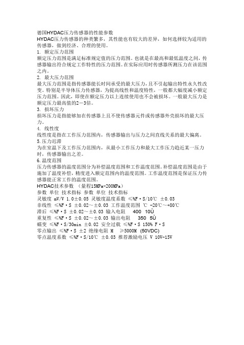
德国HYDAC压力传感器的性能参数HYDAC压力传感器的种类繁多,其性能也有较大的差异,如何选择较为适用的传感器,做到经济、合理的使用。
1. 额定压力范围额定压力范围是满足标准规定值的压力范围。
也就是在最高和最低温度之间,传感器输出符合规定工作特性的压力范围。
在实际应用时传感器所测压力在该范围之内。
2. 最大压力范围最大压力范围是指传感器能长时间承受的最大压力,且不引起输出特性永久性改变。
特别是半导体压力传感器,为提高线性和温度特性,一般都大幅度减小额定压力范围。
因此,即使在额定压力以上连续使用也不会被损坏。
一般最大压力是额定压力最高值的2-3倍。
3. 损坏压力损坏压力是指能够加在传感器上且不使传感器元件或传感器外壳损坏的最大压力。
4. 线性度线性度是指在工作压力范围内,传感器输出与压力之间直线关系的最大偏离。
5.压力迟滞为在室温下及工作压力范围内,从最小工作压力和最大工作压力趋近某一压力时,传感器输出之差。
6.温度范围压力传感器的温度范围分为补偿温度范围和工作温度范围。
补偿温度范围是由于施加了温度补偿,精度进入额定范围内的温度范围。
工作温度范围是保证压力传感器能正常工作的温度范围。
HYDAC技术参数(量程15MPa-200MPa)参数单位技术指标参数单位技术指标灵敏度 mV/V 1.0±0.05 灵敏度温度系数≤%F·S/10℃±0.03非线性≤%F·S ±0.02~±0.03 工作温度范围℃ -20℃~+80℃滞后≤%F·S ±0.02~±0.03 输入电阻 400 10Ù重复性≤%F·S ±0.02~±0.03 输出电阻 350 5Ù蠕变≤%F·S/30min ±0.02 安全过载≤%F·S 150% F·S零点输出≤%F·S ±2 绝缘电阻 M≥5000M(50VDC)零点温度系数≤%F·S/10℃±0.03 推荐激励电压 V 10V-15V。

压力表检定注意事项及调校方法江门市新会区质量技术监督检测所张鑫压力表是指以弹性元件为敏感元件,测量并指示高于环境压力的仪表,应用极为普遍,它几乎遍及所有的工业流程和科研领域。
在热力管网、油气传输、供水供气系统、车辆维修保养厂店等领域随处可见。
尤其在工业过程控制与技术测量过程中,由于机械式压力表的弹性敏感元件具有很高的机械强度以及生产方便等特性,使得机械式压力表得到越来越广泛的应用。
本人根据JJG52-2013压力表检定规程,总结了对弹簧管压力表检定工作中常见故障的原因及处理办法。
弹簧管式一般压力表是指结构为单圈“C”型弹簧管(如图),用于测量对仪表零件不起腐蚀作用的液体、气体和蒸汽的压力的仪表。
通过掌握压力参数,为操作人员监视、控制和调节生产提供可靠的依据,同时了解生产过程中物料变化状态,控制生产工艺参数,保证了产品质量。
因此,压力表指示正确与否直接关系到企业的生产安全和产品质量。
根据自己几年来的计量检定工作,本着为企业解决问题,节约成本的服务宗旨,在对企业送检的压力表检定工作中,总结出了以下几点:一、压力表检定的步骤压力表在安装使用前,应经国家认可的计量部门对压力表进行检定,并出具检定合格证书,方可安装进行使用。
主要检定步骤如下:1.外观检查:计量检定人员应根据JJG52—2013规程要求进行检定。
首先进行外观检查,用目力观测压力表的外形、标志、读数部分、测量上限量值数字、分度值等内容。
在观测零位时注意对带有止销和没有止销的要区别对待,看是否符合检定规程中的要求,并在检定记录上记录检查结果。
根据被检表量程选取同量程标准表和大于其量程的校验器。
根据规程要求,选择标准表的允许误差绝对值应不大于被检压力表允许误差绝对值的1/4。
这样才能准确反映出被检表的实际值。
2.标准表的选用:我们在日常检定中选用的标准表是弹簧管式精密压力表和真空表,辅助设备是压力校验仪和真空校验仪。
将标准表和被检表安装在校验仪上,被检表若是氧气、乙炔等禁油表,则应安装在与油水分离器连接的禁油接头上,检查和调整校验仪,排除油路中的空气,使各部位作用良好。

德国贺德克安全阀压力如何调整的呢①调整阀门排放压力和回座压力,必须进行阀门达到全开启高度的动作试验,因此,只有在大容量的试验装置上或者在安全阀安装到被保护设备上之后才可能进行。
其调整方法依阀门结构不同而不同。
②对于带反冲盘和阀座调节圈的结构,是利用阀座调节圈来进行调节。
拧下调节圈固定螺钉,从露出的螺孔伸人一根细铁棍之类的工具,即可拨动调节圈上的轮齿,使调节圈左右转动。
当使调节圈向左作逆时针方向旋转时,其位置升高,排放压力和回座压力都将有所降低。
反之,当使调节圈向右作顺时针方向旋转时,其位置降低,排放压力和回座压力都将有所升高。
每一次调整时,调节:圈转动的幅度不宜过大(一般转动数齿即可)。
每次调整后都应将固定螺钉拧上,使其端部位于调节圈两齿之间的凹槽内,既能防止调节圈转动,又不对调节圈产生径向压力。
为了安全起见,在拨动调节圈之前,应使安全阀进口压力适当降低(一般应低于开启压力的90%),以防止在调整时阀门突然开启,造成事故。
③对于具有上、下调节圈(导向套和阀座上各有一个调节圈)的结构,其调整要复杂一些。
阀座调节圈用来改变阀瓣与调节圈之间通道的大小,从而改变阀门初始开启时压力在阀瓣与调节圈之间腔室内积聚程度的大小。
当升高阀座调节圈时,压力积聚的程度增大,从而使阀门比例开启的阶段减小而较快地达到突然的急速开启。
因此,升高阀座调节圈能使排放压力有所降低。
应当注意的是,阀座调节圈亦不可升高到过分接近阀瓣。
那样,密封面处的泄漏就可能导致阀门过早地突然开启,但由于此时介质压力还不足以将阀瓣保持在开启位置,阀瓣随即又关闭,于是阀门发生频跳。
阀座调:《圈主要用来缩小阀门比例,开启的阶段和调节排放压力,同时也对回座压力有所影响。
上调节圈用来改变流动介质在阀瓣下侧反射后折转的角度,从而改变流体作用力的大小,以此来调节回座压力。
升高上调节圈时,折转角减小,流体作用力随之减小,从而使回座压力增高。
反之,当降低上调节圈时,回座压力降低。
压力表校准方法
1.目的:确保压力表精度
2.范围:适用压力表精度,外观校准
3.调校步骤(标准表比较法)
3.1仪表的安装与排汽
将标准表与被校表分别安装于同一个管上,检查两个表上显示的值是否一致。
排汽方法如下:新安装、拆装的压力表,须进行排汽工作,关闭气路阀门,先逆时针转动手柄抽气,再顺时针转动手柄排气。
多次反复进行并随时观察油面排气情况,直至无气泡排出为止。
3.2检查零点
应在没有压力情况下检查压力表是否归零点
3.3加压校验
打开气阀,对比标准表和被校准表显示的压力值是否一致。
压力表调节方法
压力表调节方法:
一、观察安全运行范围:
(1)先检查规定的最高最低压力之间的差异,以免超出安全运行范围。
(2)确定系统使用的介质,以便确保运行参数符合介质的性质要求。
(3)根据当前的需要不断观察压力是否已经超出了安全运行范围。
二、热平衡调节:
(1)通过有效的热源和温度调节器,控制流入介质的介质温度,来获
得所需的压力。
(2)在调节介质温度时,应注意保持合理的环境温度,以确保正常运行。
(3)使用热增强技术,来改善热热平衡实现压力稳定性。
三、机械式调节:
(1)将机械部件与调节器结合,使压力在规定范围内调节和维持它的参数。
(2)调节盘、调节锁和环境补偿可以最大程度地调节压力。
(3)压力控制装置的部件应具有耐磨性和耐腐性,以确保其性能稳定可靠。
四、设置安全阀和开关:
(1)可以采用安全阀和开关,以便调节压力,以确保系统安全运行。
(2)阀门内活塞和开关手柄应具有不断升级,可以实现更高准确度的调节。
(3)调节压力时,应注意系统流量及其替代方式,以保证正确操作。
压力修正说明
首先进入参数设定
(1)同时按下EN、键,仪表进入参数设定界面,此时屏幕上方显示设定的参数项目,下方显示设定值。
(2)按EN键到需要更改的参数项,按键移动光标到要更改的数字处,然后按键更改参数设置,设置完后需要再次按下EN 键保存该设置,仪表保存该参数后自动跳到下一项参数,若不需要继续修改参数值,同时按下EN、键退出参数设定界面。
(3)参数设定完毕,需要将仪表重启,即关闭仪表看到显示屏完全没有数字显示后再次开启仪表。
(4)参数说明
使用P002,P003进行修正
P002:压力修正比例系数,默认100;
P003:压力修正零位,默认100。
修正之后的值= (1+(P_set[2]-100)/1000.0)×原始测量值+(P_set[3]-100.0)/50.0。