智能压力控制器EA-SK01系列
- 格式:doc
- 大小:192.50 KB
- 文档页数:2

EASK智能数显压力变送控制器20 年月日A4打印/ 可编辑EA-SK智能数显压力变送控制器使用说明书一、概述EA-SK智能数显压力变送控制器是集压力测量、显示、控制、变送于一体的多功能产品。
该产品采用微型计算机数字技术, 前端有高性能带隔离膜充油芯体的压力传感器,输入信号经高精度、低温漂的放大电路, 由单片机进行数字处理, 实现操作/显示/控制/变送, 能同时控制/变送。
它使用方便,广泛应用于电力、水处理、石油、化工、冶金、机械、塑料、空调设备等行业,对介质的压力进行检测控制,是指针仪表的理想替代产品, 可作为基地式仪表或用于自动控制系统中。
该产品有高亮数码显示,有很强的抗干扰能力, 也防止在压力控制临界点继电器抖动误操作,产品的可靠性高。
每一个控制输出点都有一常开触点和一个常闭触点及一个报警指示灯, 使用方式灵活。
我们可根据用户要求,生产单点控制、双点控制的产品, 也能提供多种标准变送输出信号。
二、主要性能技术指标1、压力范围:-0.1--100MPa2、电源电压:220V AC 或11-20V DC3、输出信号:4--20mA、1--5V、0--10mA、0--5V DC4、环境条件:使用温度:-l0 ℃--60℃(介质温度为-10℃--120℃)相对湿度:0~80%;存储:-40℃~125℃5、最大压力:1.5-3倍满量程压力;最大功耗: <2W6、继电器负载能力:250V/3A(AC) 24V/3A(DC) 继电器触点寿命:>100000次7、主屏显示:4位0.4英寸LED红色; 下屏显示:4位0.28英寸LED红色三、接线端子示意图1,2:220V3:大地4, 5: 下限常开5, 6: 下限常闭7, 8:下限常开8,9:下限常闭四、功能设定示意图1 L(V+)2 N(V-)3 GND4 ON5 JKH6 OFF7 ON8 JKL9 OFF10 COM11 VO12 IO功能键① 功能键② 功能键③1.按下功能键①键,当SP 显示SPH1时,请设定第一报警点 [根据3.4.5.](双点控制用)2.按下功能键①键,当SP 显示SPL 时,请设定第二报警点压力值 [根据3.4.5.]3.功能键②为数字移位功能;4.功能键③为0----9数字循环显示;5.小数点设定:当想移动小数点时,请按下功能键②使数码管在小数点的后一位闪动,然后按住功能键②一秒后,小数点会自动跳到下一位;6.设定完成以后按住功能键①键一秒以后,完成全部设定.注意:请勿拆卸传感器接头!F Mp aPVSP整理丨尼克本文档信息来自于网络,如您发现内容不准确或不完善,欢迎您联系我修正;如您发现内容涉嫌侵权,请与我们联系,我们将按照相关法律规定及时处理。
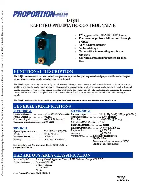
ISQB1ELECTRO-PNEUMATIC CONTROL V ALVEThe ISQB1 series control valve is an electronic pressure regulator designed to precisely and proportionally control the pres-sure of gaseous media based on an electronic control signal.The ISQB1 operates using two normally closed solenoid valves, a pressure sensor, and a control circuit. One valve is actu-ated to allow supply media into the system. The second valve is actuated to allow working media to vent through a threaded port to atmosphere. The pressure sensor provides feedback to the control circuit. The control circuit compares the pressure sensor feedback to the user supplied electronic command signal and actuates the appropriate valve until the two signals match.The ISQB1 series can be teamed with a variety of air piloted pressure volume boosters for even greater flow.MECHANICALPressure ranges…………...…29.9 in. Hg (VAC) -150 psig (10.3bar) Output Pressure……………...0-100% of range Flow Rate…………………….0.80 SCFM @ 80 psig Min. Closed End Volume……1 in³Filtration Required…………..20 micron Linearity/Hysterisis…………..< 0.4% F.S. B.F.S.L Repeatability………………....< 0.2% F.S. Accuracy……………………..< 0.5% F.S. Wetted Parts…………Elastomers-Fluorocarbon Manifold-Brass Transducer-Silicon, Aluminum, RTV Valves-Nickel Plated Brass ELECTRICALSupply Voltage….………….…..14.5VDC-29VDC (MAX) Supply Current…………………<80mA Command Signal.………………4-20mA Differential Command Signal Impedance…..100 OHMPHYSICALOperating temperature…..…..…32-150ºF (0-70ºC) (T4)Weight………………………….2.5 lb. (1.1 kg)Protection Rating……………….NEMA 4Housing…………………………Anodized AluminumSee Installation & Maintenance Guide ISBQ1-MS1 for proper installation.Intrinsically Safe……...Factory Mutual Approval- Class I, II, III, Division 1Groups C,D,E,F,GEntity Parameters……..V Max = 29VDC I Max = 150mA Ci = 0.24uF Li = 0Field Wiring Drawing: ISQB-96026-2• FM approved for CLASS 1 DIV 1 areas • Pressure ranges from full vacuum through 150psig• NEMA4/IP65 housing • No bleed design• Not sensitive to mounting position or vibration•Use with air piloted regulators for high flowC o u r t e s y o f C M A /F l o d y n e /H y d r a d y n e ▪ M o t i o n C o n t r o l ▪ H y d r a u l i c ▪ P n e u m a t i c ▪ E l e c t r i c a l ▪ M e c h a n i c a l ▪ (800) 426-5480 ▪ w w w .c m a f h .c o mACCESSORIESC o u r t e s y o f C M A /F l o d y n e /H y d r a d y n e ▪ M o t i o n C o n t r o l ▪ H y d r a u l i c ▪ P n e u m a t i c ▪ E l e c t r i c a l ▪ M e c h a n i c a l ▪ (800) 426-5480 ▪ w w w .c m a f h .c o m。

Digital Pressure Control SystemEaton’s Carter® product line of ground refueling equipment includes the 4th Edition of our Digital Pressure Control System, which employs a proprietary method of controlling and monitoring fuel pressure into the aircraft. The combination of Hydro-mechanical valves and a microprocessor eliminates the need for air-reference pressure, servo controls or venturis to control pressure.Fuel cannot cross contaminate the air system such as occurs in air operated systems.Eaton’s Carter Digital Pressure Control System with dual controllers operates both the primary and secondary pressure controlsduring the fueling operation and eliminates the interference gap created by purely mechanical systems. This allows for maximum flow throughout the total fueling cycle and reduced backpressure interference. The improved flow reduces overall fueling time allowing for faster fueling turns, minimized gate delays, andsmaller fleet size.The system can be operated with all existing industry standard configurations with either single or dual pressure controllers.Adjustments for pressure control, rate of flow control, opening and closing times are set by connecting a laptop through a provided graphical user interface (GUI) software application. The systemis tamper proof with user level security or can be unplugged and stored by an authorized technician. Once the Laptop is removed, the fueling operator cannot make any further changes. There are no buttons or key locks on the Display module making this a safer and tamper resistant system.Higher flow rates are achieved due to lower system pressuredrop as compared to a conventional system. Initial Setup timeand subsequent periodic maintenance is also reduced throughthe provided software by automatically calculating flow resistance without an iterative manual adjustment process.The Display Control Module (DCM) denotes which nozzles are being used, the units of measure for the pressure settings and the rate of flow. Each nozzle has a specific profile stored into the digital system which maximizes fueling efficiency.Multiple remote displays can be procured to provide readouts for various locations on the vehicle or lift decks.The Digital IV diagnostic error readouts are highly descriptivewhich reduces maintenance time and improves troubleshooting effectiveness. Error logs can be extracted for further analysis.Eaton’s Carter® Digital Pressure Control System can be installed on new build Refuelers and Hydrant Servicers or installed as a retrofit to existing equipment. Eaton will also support upgrades from an earlier version of Eaton’s Carter Digital Pressure Control System.System Components(Each purchased separately)• 64435 - Pressure Control System• 64436 - Display Control Module or Remote Display control module • Wire Harness Kits• 64302, 64303 or 64304 Solenoid Manifold for Pressure Control Coupler operation• 64902 - Digital 4-inch Pressure Control Coupler or• 64802/64804 - Digital 3-inch Pressure Control Coupler• 64504 - Digital 3-inch Inline Valve• 64505 - Digital 3-inch Bypass Valve• 64514 - Digital 4-inch Inline Valve• 64515 - Digital 4-inch Bypass ValveFeatures• Easy User interface• Accurate control• Future enhancements through upgradeable software• Detailed Diagnostics Features• 7” LCD color display• Displays nozzle pressure and flow simultaneously• Display module shows which nozzles are being used• No Venturi (s) required• No air reference pressure required• No fuel-to-air cross contamination• Maximum rate of flow control standard. No rate of flow valve required• Optional 7” LCD color Remote displays available• Robust IP67 pressure control modules• Three different units of pressure and flow readouts on the module (e.g. psi, kpa, bar)• Adjustable timer deadman- standard• Deadman warning message will display on display screen& the same time beacon will illuminate provide alertmessage to operator• Error message will display on screen to assist withtrouble shooting• System can be used with Inline or Bypass Valves and Pressure control hydrant couplers (Hydrant coupler)• All calibrations done using a common laptop computer• Up to six hose profiles can be individually calibrated• System can receive inputs from two meters simultaneously• Tamper Proof calibration64435 T otal Pressure Control SystemATEX and IECEx certification in progress.Follow us on social media to get thelatest product and support information.Eaton is a registered trademark.All other trademarks are propertyof their respective owners.Eaton1000 Eaton Boulevard Cleveland, OH 44122 United States © 2017 EatonAll Rights Reserved Printed in USA Artical No. DS100-116A September 2017。
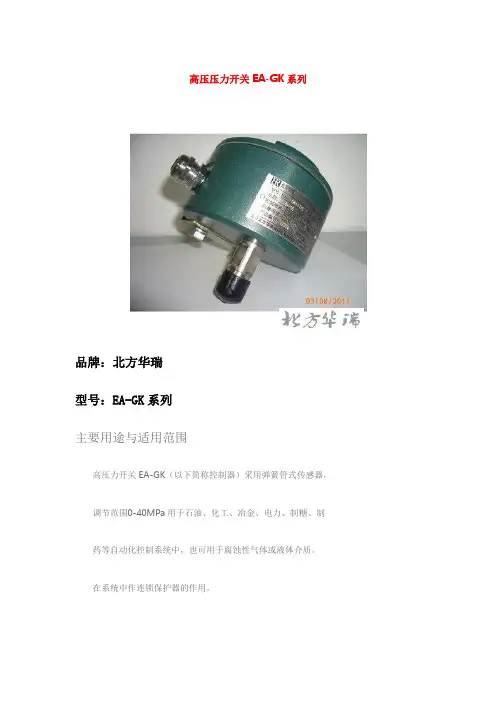
高压压力开关EA-GK系列
品牌:北方华瑞
型号:EA-GK系列
主要用途与适用范围
高压力开关EA-GK(以下简称控制器)采用弹簧管式传感器,调节范围0-40MPa用于石油、化工、冶金、电力、制糖、制
药等自动化控制系统中,也可用于腐蚀性气体或液体介质。
在系统中作连锁保护器的作用。
技术指标
工作粘度≤ 1 x 10⁻³m2/s
环境温度:-15℃~ 55℃
环境湿度:5%~95%
重复性误差:<1.5%
使用寿命:105次循环
抗振性:<Max.2g
外壳保护等级:IP65
额定负荷:Vmax= 380V Z max= 5A
高压开关EA-GK系列切换差不可调
量程MPa 切换差
MPa
不大于
最大允
许压力
MPa
切换
频率
传感器材质螺纹接口
订货型号
普通防爆
1-10 0.25 15 30次/1Cr18Ni9Ti M20×1.5外EA-GK411/A EA-GK411/E
分
30次/
1-16 0.25 20
1Cr18Ni9Ti M20×1.5外EA-GK411/A EA-GK411/E
分
30次/
2-25 0.5 32
1Cr18Ni9Ti M20×1.5外EA-GK411/A EA-GK411/E
分
30次/
1Cr18Ni9Ti M20×1.5外EA-GK411/A EA-GK411/E 2-40 1.5 50
分。
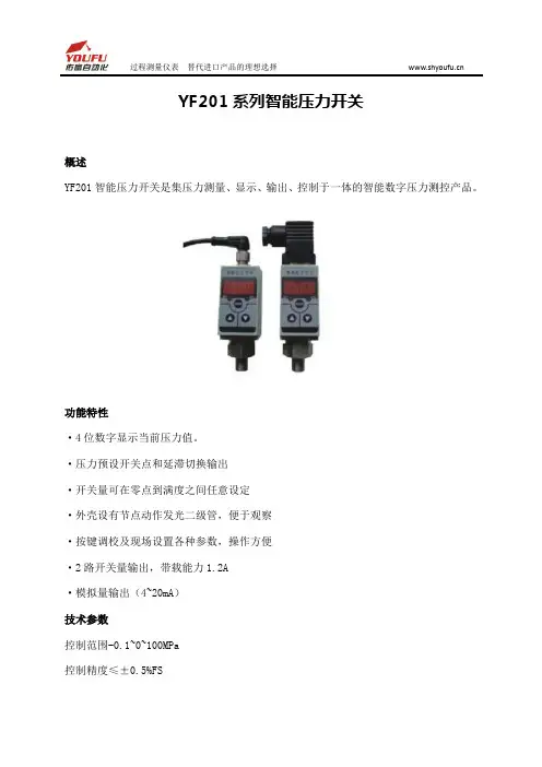
YF201系列智能压力开关
概述
YF201智能压力开关是集压力测量、显示、输出、控制于一体的智能数字压力测控产品。
功能特性
·4位数字显示当前压力值。
·压力预设开关点和延滞切换输出
·开关量可在零点到满度之间任意设定
·外壳设有节点动作发光二级管,便于观察
·按键调校及现场设置各种参数,操作方便
·2路开关量输出,带载能力1.2A
·模拟量输出(4~20mA)
技术参数
控制范围-0.1~0~100MPa
控制精度≤±0.5%FS
稳定性≤0.2%/年
温度漂移±0.02%FS/℃
显示方式4位数码管
显示范围-1999~9999
电源范围24VDC±20%
zui流消耗<60mA
负载容量<24V1.2A
开关类型PNP/NPN
选型代码
拓展阅读:
压力开关采用高精度、高稳定性能的压力传感器和变送电路,再经专用CPU模块化信号处理技术,实现对介质压力信号的检测、显示、报警和控制信号输出。
压力开关可以广泛用于石油、化工、冶金、电力、供水等领域中对各种气体、液体的表压、绝压的测量控制,是工业现场理想的智能化测控仪表。
压力控制器以及压力开关产品使用手册目录第一章MD-S200 电池供电型数字压力表使用手册第二章MD-S500数字式远传型压力表使用手册第三章MD-S600高精度智能压力开关使用手册第四章MD-S700机械式压力开关使用手册第五章MD-S800低成本压力开关使用手册第六章MD-S910W/910C水泵压力控制器/空压机控制器使用手册第七章MD-S910F分体式压力控制器使用手册第八章MD-S系列产品的安装与电气连接第九章MD-S系列产品的日常养护第十章产品的运输与保存第十一章常见故障及解决办法第十二章 MD-S系列产品质量保证服务主要特点:※技术先进,质量控制体系严格,通过权威认证※设计时的第一原则是:实用及安全的原则※全系列通过权威认证注意:1.请留意手册中出现的带有※(!)(?)等提醒字样的语言!2.文中出现的“不得”“禁止”等明显禁止的语言时,请注意严格按照其要求操作。
第1章MD-S200电池供电型数字压力表MD-S200电池供电型智能压力表是是集压力测量、显示一体的高精度电子式压力表,具有抗震动、显示精度高、使用寿命长、可清零、自动待机等特点。
无需外接电源,电池供电时间长,具有自动待机与一键清零功能,使用方便,应用领域广泛。
一.外形图1.压力显示窗口2.设置键(SET)3.压力安装接口二.系统参数压力量程0-1.6MPA 或定制量程安装接口M20*1.5精度等级0.5%显示位数4位LCD显示背光蓝色背光尺寸直径100mm 厚度48m供电 4.5V 三节5号电池功耗0.001W电池更换通常每12个月更换一次电池(以实际使用耗电量为准)使用温度-20~60℃功能 1.实时显示压力 2.自动休眠 3.一键清零 4.单位切换三.按键定义说明设置键(SET)键:1.短按SET键一次,背光亮。
2.连续短按SET键,压力的显示单位在Mpa,Kg,PSI之间切换,默认单位为Mpa。
四.一键清零功能操作方法:长按SET键5秒,可以一键清零。
美国UE压力开关说明:美国UE压力开关产品介绍:H100系列(通用型压力真空温度开关):H100-483 H100-484 H100-485 H100-486 H100-488 H100-489 H100-490 H100-491H100-492 H100-493 H100-494 H100-520 H100-521 H100-522 H100-523 H100-524 H100-525 H100-530 H100-531 H100-532H100-533 H100-534 H100-535 H100-560 H100-561 H100-562 H100-563 H100-564 H100-565 H100-566 H100-567 H100-610H100-612 H100-616 H100-680 H100-701 H100-702 H100-703 H100-704 H100-705 H100-706 H100K系列:H100K-540 H100K-541 H100K-542 H100K-543 H100K-544 H100K-545 H100K-546 H100K-547 H100K-548J120系列(危险区域安装的压力开关真空开关差压开关和温度开关):J120-126 J120-134 J120-137 J120-144 J120-152J120-156 J120-164 J120-171 J120-172 J120-173 J120-174 J120-183 J120-190 J120-193 J120-356 J120-450 J120-483J120-484 J120-488 J120-520J402K系列:J402K-147 J402K-157 J402K-455 J402K-456 J402K-457 J402K-559 J402K-S147B J402K-S157B J402K-540J402K-541 J402K-542 J402K-543 J402K-544 J402K-545 J402K-546J400K系列(通用型多点输出压力真空温度开关):J400K-147 J400K-157J400K-455 J400K-456 J400K-457 J400K-559 J400K-S147B J400K-S157BJ120K系列:J120K-36 J120K-37 J120K-38 J120K-39 J120K-147 J120K-157J120K-367 J120K-455 J120K-456 J120K-457 J120K-540 J120K-541 J120K-542J120K-543 J120K-544 J120K-545 J120K-546 J120K-547 J120K-548 J120K-559J120K-S147B J120K-S157BH100系列:H100-171 H100-172 H100-173 H100-174 H100-183 H100-184 H100-185 H100-186 H100-188 H100-189 H100-190H100-191 H100-192 H100-193 H100-194 H100-218 H100-270 H100-274 H100-358 H100-361 H100-376;J403系列压力开关:J403-S134B J403-S137B J403-S144B J403-S146B J403-S156B J403-S164B J403-126 J403-134 J403-137 J403-144 J403-146 J403-156J403-164 J403-270 J403-274 J403-358 J403-361 J403-376 J403-442J403-443 J403-448 J403-450 J403-451 J403-452 J403-453 J403-454J403-550 J403-551 J403-552 J403-553 J403-554 J403-555 J403-570J403-571 J403-572 J403-610 J403-612 J403-614 J403-S126B H403-126H403-134 H403-144 H403-146 H403-156 H403-164 H403-358 H403-361 H403-376H403-S126B H403-S134B H403-S144B H403-S146B H403-S156B H403-S164B;H402K系列压力开关:H402K-455 H402K-456 H402K-457 H402K-559U系列压力开关:U-10D-10 U-12SHSN2C U-12SHSN3A U-12SHSN3D U-24-013U-24-014 U-24-014-M262 U-2S260L4-316 U-3611SB1 U-B402-120 U-H100-171U-H100-172 U-H100-173 U-H100-174 U-H100-184 U-H100-185 U-H100-188U-H100-189 U-H100-190 U-H100-191 U-H100-192 U-H100-193 U-H100-194U-H100-194-M449 U-H100-218 U-H100-358 U-H100-491 U-H100-520U-H100-522 U-H100-524 U-H100-533 U-H100-534 U-H100-567 U-H100-612U-H100-612-0500 U-H100-616 U-H100-701 U-H100-702 U-H100-703U-H100-704 U-H100-705 U-H100-705-M540 U-H100-706 U-H100K-540U-H100K-544 U-H121K-S147B-M210 U-H122-361 U-H122-612 U-H122-S126BU-H122-S146B U-H122-S156B U-H177-188 U-E122-2BSB-W050 U-J120-126U-J120-134 U-J120-144 U-J120-171 U-J120-173 U-J120-189 U-J120-190U-J120-190-0140 U-J120-190-1190 U-J120-191 U-J21K-254 U-J120-192U-J120-193 U-J120-194 U-J129K-36 U-J120K-S147B U-J120-560 U-J6-136U-J120K-457-M277 U-J120K-541-0140 U-J40-222 U-J400K-157 U-J400K-455U-J400K-456 U-J402K-455 U-J400-156 U-J400-164 U-J402-126 U-J402-164U-J402-454 U-J402-455 U-J402-612 U-J400-S156B U-J402-S156B U-J6-230 EchoSpan超声波液位计:LU81-5101 LU81-5161 LU83-5101 LU83-5161 LU84-5101 LU84-5161支架:LM50-1001(2"NPT) LM50-1061(2"G)EchoTouch超声波液位计:LU20-5001 LU20-5061 LU30-5003 LU30-5004 LU30-5063 LU30-5064EchoSafe隔爆型超声波液位计:XP88-00 XP89-00 XP88-02 XP89-02 支架:LM50-1001MiniMe紧凑型超声波液位计:LU12-5001 LU12-5061 LU11-5001 LU11-5061 LU13-5001 LU13-5061LU05-5001 LU05-5061 支架:LM50-1001EchoPod超声波液位控制器:DL14-00 DL14-01 DL14-11 DL14-10 DS14-00 DS14-01 DS14-11 DS14-10DL10-00 DL10-01 DL10-11 DL10-10 DX10-00 DX10-01 DX10-11 DX10-10接口:LI99-1001EchoSonic II超声波液位计:LU26-5001 LU26-5011 LU27-5001 LU27-5011 LU28-5001 LU28-5011LU29-5001 LU29-5011 标准探头带3米缆线,最大可以加长到7.6米,订货型号加-15.例如:LU28-00-15 支架:LM50-1001-1(1"NPT) LM50-1061-1(1"G)LM50-1001(2"NPT) LM50-1061(2"G)EchoSwich II多点超声波液位开关:LU77-5005 LU77-5065 LU78-5005 LU78-5065支架:LM50-1001-1(1"NPT) LM50-1061-1(1"G)LM50-1001(2"NPT) LM50-1061(2"G)音叉液位开关:LZ12-1405 LZ12-1425 传感器电缆:额外订购25'或者50'传感器电缆,将电缆的长度型号末尾注明.例如:LZ12-1405-25'超声波液位开关:LU10-1305 LU10-1405 LU10-1325 LU10-1425LU10-2305 LU10-2405 LU10-2325 LU10-2425浮子开关:LV20-1201 LV20-1221 LV20-5201 LV20-5221传感器电缆额外订购25'或者50'电缆,需要在型号后面注明长度.例如:LV20-1201-25'LV30-S201 LV31-S201 LV32-S201 LH23-1201 LH30-S301LV10-1301 LV10-1351 LV10-5301 LV10-5351传感器电缆额外订购25'或者50'电缆,需要在型号后面注明长度.例如:LV10-1301-25'热式流量开关:FT10-1305 FT10-1405 FT10-1325 FT10-1424FT10-5305 FT10-5405 FT10-5325 FT10-5424 标准探头带2.5米电缆,最大可以加长到25'或50',定货型号要加-25'例如FT10-1405-25'.PP材料FT50-1000PVDF材料FT50-5000 集装配置A T14/12。
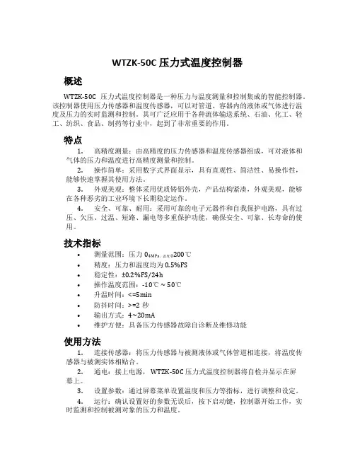
WTZK-50C 压力式温度控制器概述WTZK-50C 压力式温度控制器是一种压力与温度测量和控制集成的智能控制器。
该控制器使用压力传感器和温度传感器,可以对管道、容器内的液体或气体进行温度及压力的实时监测和控制。
其可广泛应用于各种流体输送系统、石油、化工、轻工、纺织、食品、制药等行业中,起到了非常重要的作用。
特点1.高精度测量:由高精度的压力传感器和温度传感器组成,可对液体和气体的压力和温度进行高精度测量和控制。
2.操作简单:采用数字式界面显示,具有直观性、简洁性、易操作性,能够快速掌握其使用方法。
3.外观美观:整体采用优质铸铝外壳,产品结构紧凑,外观美观,能够在各种恶劣的工业环境下长期稳定运作。
4.安全、可靠、耐用:采用可靠的电子元器件和自我保护电路,具有过压、欠压、过温、短路、漏电等多重保护功能,确保安全、可靠、长寿命的使用。
技术指标•测量范围:压力04MPa,温度0200℃•精度:压力和温度均为0.5%FS•稳定性:±0.2%FS/24h•操作温度范围:-10℃ ~ 50℃•升温时间:<=5min•防抖时间:>=2秒•输出方式:4~20mA•维护方便:具备压力传感器故障自诊断及维修功能使用方法1.连接传感器:将压力传感器与被测液体或气体管道相连接,将温度传感器与被测实体相贴合。
2.通电:接上电源, WTZK-50C 压力式温度控制器将自检并显示在屏幕上。
3.设置参数:通过屏幕菜单设置温度和压力等指标,进行调整和设定。
4.运行:确认设置好的参数无误后,按下启动键,控制器开始工作,实时监测和控制被测对象的压力和温度。
5.故障处理:若出现故障,可通过屏幕信息快速定位问题所在,并进行修复。
注意事项1.请按照正确的方法使用和安装该控制器,避免控制器被损坏或者造成安全问题。
2.在产品使用之前,请确认所有连接均已牢固并符合操作要求。
3.建议定期检查并对产品进行清洁和保养工作,以确保产品正常运转。
艾默生CT变频器代理商咨询电话:0755-******** QQ:2407299229EV1000、EV2000高性能通用型艾默生变频器G为恒转矩负载,P为风机水泵负载(EV1000:0.4-5.5KW EV2000:5.5-280KW)EV1000-2S0004G 单相220VAC 0.4KW EV1000-2S0007G 单相220VAC0.75KW EV1000-2S0015G 单相220VAC 1.5KW EV1000-2S0022G 单相220VAC 2.2KW EV1000-4T0007G 三相380VAC0.75KW EV1000-4T0015G 三相380VAC1.5KW EV1000-4T0022G 三相380VAC2.2KW EV1000-4T0037G 三相380VAC3.7KW EV1000-4T0055G 三相380VAC5.5KW EV1000-4T0037P 三相380VAC3.7KW EV1000-4T0055P 三相380VAC 5.5KWEV2000-4T0055G/0075P 5.5KW/7.5KW EV2000-4T0075G/0110P7.5KW/11KW EV2000-4T0110G/0150P 11KW/15KW EV2000-4T0150G/1085P 15KW/18.5KW EV2000-4T0185G1/0220P118.5KW/22KW EV2000-4T0220G1/0300P1 22KW/30KW EV2000-4T0300G1/0370P1 30KW/37KW EV2000-4T0370G/0450P37KW/45KW EV2000-4T0450G1/0550P1 45KW/55KW EV2000-4T0550G 55KW EV2000-4T0750G 75KW EV2000-4T0900G 90KW EV2000-4T1100G 110KW EV2000-4T1320G 132KW EV2000-4T1600G 160KW EV2000-4T2000G 200KW EV2000-4T2200G 220KW EV2000-4T0750P 75KW EV2000-4T0900P 90KW EV2000-4T1100P 110KW EV2000-4T1320P 132KW EV2000-4T1600P 160KW EV2000-4T2000P 200KW EV2000-4T2200P 220KW EV2000-4T2800P 280KWEV3000系列矢量艾默生变频器(2.2KW-220KW)EV3000艾默生变频器是高品质、多功能、低噪音的矢量控制通用变频器。
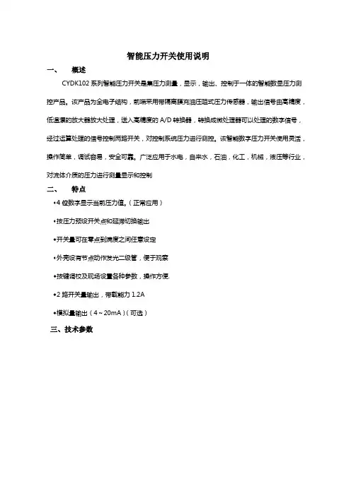
智能压力开关使用说明一、概述CYDK102系列智能压力开关是集压力测量,显示,输出、控制于一体的智能数显压力测控产品。
该产品为全电子结构,前端采用带隔离膜充油压阻式压力传感器,输出信号由高精度,低温漂的放大器放大处理,送入高精度的A/D转换器,转换成微处理器可以处理的数字信号,经过运算处理的信号控制两路开关,对控制系统压力进行测控。
该智能数字压力开关使用灵活,操作简单,调试容易,安全可靠。
广泛应用于水电,自来水,石油,化工,机械,液压等行业,对流体介质的压力进行测量显示和控制二、特点◆4位数字显示当前压力值。
(正常应用)◆按压力预设开关点和延滞切换输出◆开关量可在零点到满度之间任意设定◆外壳设有节点动作发光二级管,便于观察◆按键调校及现场设置各种参数,操作方便.◆2路开关量输出,带载能力1.2A◆模拟量输出(4~20mA)(可选)三、技术参数四.安装4.1电气连接:1(红色)电源+2(黑色)电源-3(白):模拟输出4(兰色):开关1 5(绿色)开关24.2壳体结构:控制范围-0.1…0~0.01…100MPa 控制精度≤±0.5%FS稳定性≤±0.5% /年显示精度±0.1%FS显示方式4位0.36"数码管2个LED灯显示范围-1999~9999 电源范围24V±20% 电源影响≤±0.1%FS最大功耗< 3W 引线方式M12工业连接器输出模式两路开关量+一路模拟量负载容量<24V1.2A防护等级IP65 开关寿命>1000000次环境温度-25℃~70℃介质温度-25℃~85℃存储温度-25℃~85℃相对湿度0~80%五、设置功能总述5.1.面板及按键5.2输出功能:5.2.1开关量输出QYK102有两路开关量输出。
每路开关量输出可以设定1个压力开关点和一个开启延时值。
相应的输出会在开关点的吸合值到达时切换并在压力下降到低于释放值时回复。

YWK-50-C压力控制器概述YWK-50-C压力控制器是一款用于调节气体或流体压力的控制器。
它通过对压力传感器等部件的检测和控制,使被控制液体或气体的压力保持在设定范围内,从而保证系统正常运行。
产品特点精度高YWK-50-C压力控制器采用高精度压力传感器,能够实现精度高、重复性好的压力控制,保证了被控制气体或流体的精准调控。
稳定性强该控制器采用先进的控制策略,具有快速、准确的响应能力,能够有效防止因气体或液体压力的变化而出现的系统波动,从而保证了系统的稳定性。
操作简便YWK-50-C压力控制器采用直观、简便的控制面板,可进行快速的参数设置和调节操作,适用于各种不同的应用场合。
通用性高该控制器适用于多种各类压力控制场合,包括船舶、石油化工、冶金、食品加工等多个领域。
技术参数•控制对象:气体、液体等•量程范围:0~1.6 MPa•额定电压:AC 220V•作用方式:自动调节•精度等级:±1%•工作环境:温度 -10~55℃,湿度≤85%•外观尺寸:165×175×75mm安装与使用•在安装之前,要确认控制器和被控制对象之间的管道连接正确无误,并仔细按照产品说明书进行阅读,才能保证安装的可靠性和安全性。
•在使用过程中,如果发现控制器出现故障或异常情况,应立即停止使用并联系专业人员维修。
注意事项•YWK-50-C压力控制器只能提供对被控制对象的压力控制,不应在其它用途上运用。
•在控制器安装和使用过程中,一定要注意安全,避免人身伤害和财产损失的产生。
总结YWK-50-C压力控制器是一款具有精度高、稳定性强、操作简便和通用性高等优点的压力控制器。
它广泛适用于船舶、石油化工、冶金、食品加工等领域,是一款值得信赖的设备。
在使用之前,我们需要将其安装好,并按照产品说明书进行阅读,以确保安装的可靠性和安全性。
与此同时,在使用过程中也应注意安全,以避免人身伤害和财产损失的产生。
8、电气原理图9、故障排除说明当出现以下显示字符,会直接关闭智能压力控制器的自动控制功能,运行指示灯灭,同时关闭设备。
显示字符出现的原因解决方法ER0表示所配的接触器损坏更换接触器ER1/ER2表示表自身元器件有损坏在保修期内可到经销商以旧换新ER 3“自检模式”开启状态下,设备运行后,原因①:在设定的检测时间后,没有增加压力所出现的保护字符。
原因②:在设定的检测时间内,检测到设备出现问题,比如:电机的堵转和缺相以及管子崩裂。
①同时按住“▲”与“▼”键恢复,继续增加压力便可正常工作②检查设备是否坏了ER 4“24小时内最大累计工作时间模式”开启状态下,可能①:所设的时间数<实际用水次数的累计时间所出现的保护字符。
可能②:设备出现问题,比如:压力罐单向阀长时间使用后出现损坏。
①只要同时按住“▲”与“▼”键便可恢复控制功能,可重新增加一下此模式所设的时间数,设备会照常正常工作②检查设备是否坏了ER 5“设备最大连续工作时间模式”开启状态下,可能①:所设的时间数<实际工作连续时间所出现的保护字符。
可能②:设备出现问题,比如:因井水抽干、水管漏水、水泵老化而导致的扬程降低所造成的压力罐始终达不到上限值。
①只要同时按住“▲”与“▼”键便可恢复控制功能,可重新增加一下此模式所设的时间数,设备会照常正常工作②检查设备是否坏了10、使用注意事项10.1严禁超量程使用,特殊过载请于订货前确认;10.2注意连线方法,错误的连接有可能损坏内部电路;10.3严禁用硬物深入感压孔,接触压力膜片;10.4用户不得自行拆卸;10.5如工作异常,请联系我公司售后技术人员指导调试。
智能压力控制器使用说明书。
Weitere Sicherheitsoptionen“Lockout Output” Funktion mit Störungsmeldung nach Fehleingaben, 1 - 9 Versuche programmierbar. (Nur bei Controller für 1 Tür) .Versteckter “Tamper” Schaltermeldet die gewaltsameEntfernung der Einheit.Ein “Auxiliary input” erlaubt dieferngesteuerte Öffnung für eineprogrammierte Dauer.Speicher sichert die Daten Kundenspezifische Farben Southco’s autarker Keypad Controller ist eine programmierbare Identifikationseinheit, die eigenständig elektromechanische Verschlüsse steuern kann. Mit einer Standard 12 V= Stromversorgung bietet sie den wirtschaftlichen Übergang auf eine elektronisch überwachte und gesteuerte Zugangskontrolle. Jetzt erhältlich als Controller für zwei TürenJ-EA-K1-01-M RevB visit for latest version of this document Page 1of 4Package Contents∙Standalone keypad ∙Wire harness for JA connector (9-wires with blue connector)∙Wire harness for JB connector (8-wires with white connector)∙Wire harness for JC connector (3-wires with blue connector)∙1diode ∙2mounting screws ∙Instruction guide EA-K1-01x Standalone Keypad Access Controller41234567890#1.Power LED2.Status LEDa.Solid Green:waiting for key codeb.Flashing Green:release doorc.Solid Red:lockoutd.Flashing Green and Red:programming 3.Keypad4.Return to ready state keyFeatures∙Supports seven user access codes∙Programmable door release time (1to 99seconds)∙Programmable lockout attempts (1to 9)∙Programmable lockout time (1to 99seconds)∙Programmable user and supervisor code length (4to 8digits)∙LED indicators:Power and Status∙Non-volatile memory will retain data when power is removed ∙Tamper switchSpecifications Access Code Length:Programmable 4to 8digits Monitoring Inputs:Request-to-Exit (REX)button Tamper Switch Supply Voltage:12±10%VDCStandby Current:25mA (max,no attached devices)Operating Current:65mA (max,no attached devices)Operating Temperature:0-50°COperating Humidity:20-90%RH,No condensation Dimensions:118mm x 75mm x 19mmNOTE:For indoor use only.Quick Start GuideThis section describes how to wire the keypad and program it with oneuser access code.In this section,it is assumed that the keypad is set to its default parameters (it is shipped with its default parameters).By default,no user access codes are enrolled and the supervisor code is 12345678.Basic WiringWiring the keypad for normal operation requires a connection to a 12VDC power supply and a connection to a latch.Refer to the wiring diagram at the end of these instructions for more detail.1.Plug the 9-pin blue connector (JA)into the keypad.This is the only connector you will need for this basic setup.2.Connect the red wire to a +12VDC source.3.Connect the black wire to GND at the power supply.4.Wire the relay by connecting the brown wire to +12VDC (or the voltage your application requires <30VDC)5.(Typically the normally open (NO)relay output will be used.)Connect the orange wire to the control input of the latch.∙If using the normally closed (NC)output,then connectthe yellow wire to the control input of the latch.Specific applications may require slightly different connections.Pleaserefer to the wiring diagram at the end of these instructions for detailed descriptions of each lead.Once the keypad is powered,the Power LED should be illuminatedindicating the unit is ready for use or in the “ready state.”To return to the ready state after keys have been typed,press the #key.Basic ProgrammingTo enroll a four digit user access code,choose any four digit code that does NOT begin with “9”,then:1.Enter the programming code to enroll the first user access code (9991).2.Enter the supervisor access code (default 12345678).3.Enter the new four digit user access code.Now you have set up one user code.In typical operation the keypad will function as shown below.Normal OperationIn normal operation the user can enter an access code.If the access code is accepted,the Status LED will blink green and the door actuator will be released for the time period specified.If the password is not accepted,the Status LED will turn red and the unit will beep three times.Quick Start Example:This example sets up a user access code to 43211.Enter the programming code for the first user access code:9991.2.Enter the default supervisor code:12345678.3.Enter the new user access code:4321.Now the new user access code is programmed.To restore the keypad to default settings after completing this example,type 9990followed by the default supervisor code.The user access code that was programmed in the example will be erased.Programming the KeypadTwo schemes are used in programming the keypad:standard and extended.Each process is illustrated below in flow charts.All programming functions are initiated by entering a programming code followed by the correct supervisor code.All programming codes begin with a nine.See the table below for programming codes.Code Description9990Restore default settings9991-9997Program user access codes9801-9899Program door release time9701-9799Program keypad lockout time9601-9609Program number of allowed failed attempts9504-9508Program number of digits for user access andprogramming codes9998Program eight digit supervisor codeStandard Process MapThis process diagram is used when programming the parameters listed below.Code Description9990Restore default settings9801-9899Program door release time9701-9799Program keypad lockout time9601-9609Program number of allowed failed attempts9504-9508Program number of digits for user access andprogramming codesExtended Process MapThis process diagram is used when programming the parameters listed below.Code Description9991-9997Program user access codes9998Program eight digit supervisor code Note:Once a function code has been accepted,the Status LED will remain illuminated for approximately ten seconds while it waits for the supervisor access code.If ten seconds elapse with no input,the keypad will return to normal mode.Programming Codes9990:Restore defaults(standard process map)The controller can be set to its factory default settings.To restore the default settings:1.Enter the programming code9990.2.Enter the supervisor access code(default12345678).The Status LED will flash red twice and then turn off indicating the programming is complete.After restoring the keypad,parameters will be set to the following defaults:Default SettingsAccess code length4digitsAllowed failed attempts2timesKeypad lockout time5secondsDoor release time5secondsSupervisor code123456789991–9997:Program user access codes(extended process map)Seven user access codes can be programmed using the supervisor code and the function codes9991through9997.The user access codes can be any combination of digits,except the user accesscodes cannot begin with nine(nine is reserved for programming codes).To program an access code:1.Enter one of the seven programming codes numbers(i.e.9991through9997).The Status LED will flash green,flash red,andthen remain green.2.Enter the eight digit supervisor code.The Status LED will blinkonce.J-EA-K1-01-M RevB visit for latest version of this document Page2of43.Enter the four digit user access code desired.The Status LEDwill flash red twice,and then turn off.To set another user access code,use the next available programming code9992,9993,etc.To change a user access code,use the programming code that it is paired with.For example,if9992was used to assign the user access code1234,you may change this user access code to4321by using the programming code9992.It is recommend that the supervisor keep careful records of each user access programming code, the corresponding user access code,and the individuals who use this code.9601–9609:Program allowed failed attempts(standard process map)The number of allowed failed attempts can be programmed from one to nine.This is the number of times the wrong access code can be entered (this includes both user access codes and the supervisor pass code).If this number is reached,the keypad will lock out all operation for the specified lockout time.This feature is designed to prevent trial and error tampering.To change from the default of two:1.Enter“960x”where“x”is the number of allowed failed attemptsand can range from1to9.The Status LED will flash green,flash red,and then become solid green.2.Enter the eight digit supervisor code.The Status LED will flashred,then green before turning off.9701–9799:Program keypad lockout time(standard process map)The duration of the keypad lockout time can be programmed from1to99 seconds.While locked out,the keys are not functional and The Status LED is illuminated solid red.The keypad lockout time code is97tt,where“tt”is the desired keypad lockout time in seconds.For example,if the desired keypad lockout time is30seconds,the programming code is9730.To change from the default of five seconds:1.Enter“97tt”,where“tt”is the lockout code in seconds.The StatusLED will flash green,flash red,and then become solid green.2.Enter the eight digit supervisor code.The Status LED will flashred,then green before turning off.9801–9899:Program door release time(standard process map)The length of time the door is released can be programmed from1to99 seconds.The door release time code is98tt,where“tt”is the desired door release time in seconds.For example,if the desired door release time is one minute,the programming code is9860.To change from the default of five seconds:1.Enter“98tt”,where“tt”is the door release code in seconds.TheStatus LED will flash green,flash red,and then become solidgreen.2.Enter the eight digit supervisor code.The Status LED will flashred,then green before turning off.9998:Program eight digit supervisor code(extended processmap)J-EA-K1-01-M RevB visit for latest version of this document Page3of4J-EA-K1-01-M RevB visit for latest version of this document Page 4of 4Security Monitor InputThe EA-K1-01x has a security monitor input that can be driven by an external device.Pin 8from the JA connector (purple wire)is the security monitor input.When the security monitor input is driven LOW (0V),the lockout alarm will be activated and the keypad locked out for the programmed keypad lockout time.NOTE:The Status LED will not illuminate if the security monitor input is active.Tamper SwitchThe JC connector can be used to monitor the status of the tamper switch.When the tamper switch is closed,the NO signal will be driven to the same voltage level as the COM signal.When the tamper switch is open,the NC signal will be driven to the same voltage level as the COM signal.Wiring Multiple ControllersA diode is provided with the EA-K1-01x controller.The diode allows for a keypad to be isolated when multiple controllers are connected to the same latch.Refer to the figure below for wiring details when using the diode when using multiple controllers.Connecting to an Inductive LoadA diode is provided with the EA-K1controller.This diode should be used when connecting to a device with an inductive load (for example,a relay or door strike)to protect the controller from a reverse voltage spike.The diode should be placed in parallel with the coil,as shown in the figure below.WiringDiagramAll leads marked with an “X”are notfunctional.CAUTION:Product can be damaged if wired incorrectly.Follow wiring diagramabove.CAUTION:A keypad that has been programmed is non-returnable.Please use caution in programming functions so as not to render the keypad unusable.For technical support of this product contact:****************or visit:NORMALLY OPEN (BROWN WIRE)OUTPUT,OR NORMALLY CLOSED (YELLOW WIRE)OUTPUTJ-EA-K1-02-M_revB visit for latest version of this document Page 1of 3Package Contents∙Standalone keypad∙Wire harness for JA connector (9-wires with blue connector)∙Wire harness for JB connector (8-wires with white connector)∙Wire harness for JC connector (3-wires with blue connector)∙1diode∙2mounting screws ∙Operating instructionsEA-K1Standalone Keypad Access Controller41234567890#1.Power LED2.Status LEDa.Solid Green:waiting for key codeb.Flashing Green:release doorc.Flashing Green and Red:programming 3.Keypadmand exitFeatures∙Supports 2-latch access with 150user access codes ∙Programmable door release time (1to 99seconds)∙Programmable user and instruction code length (5to 8digits)∙LED indicators:Power and Status∙Non-volatile memory will retain data when power is removed ∙Tamper switch∙For indoor use onlySpecifications Access Code Length:Programmable 5to 8digits Monitoring Inputs:Auxiliary (x2)Tamper Switch Supply Voltage:12±10%VDCStandby Current:25mA (max,no attached devices)Operating Current:65mA (max,no attached devices)Operating Temperature:0-50°COperating Humidity:20-90%RH,No condensation Dimensions:118mm x 75mm x 19mmController Mounting and InstallationPlease refer to Southco trade drawing J-EA-K1-02for mounting and installation details.Modes of OperationThere are two modes of operation for this access controller:1.User Mode –In this mode,access will be granted when a valid access code is entered or the auxiliary input asserted.An access code ending in an odd number will open the latchconnected to the JA connector.An access code ending in an even number will open the latch connected to the JB connector.2.Programming Mode –In this mode,the controller’s settings can be set by the supervisor.Types of CodesThere are three types of codes for this access controller:1.Access Code –The controller allows for 150user access codes.When a programmed access code is entered,the controller will grant access.Access codes cannot begin with a “9”.2.Supervisor Code –There is one supervisor code.This code is used to program the controller and cannot be used as an access code.The supervisor code cannot begin with a “9”.3.Instruction Code –These are used to program the varioussettings of the controller.The instruction codes are listed in the table below.Instruction CodesProgramming the Supervisor Code 99998Enrolling or Changing Access Codes 99001-99150Programming Access Code Length 99505–99508Programming Door Release Time 99801–99899Resetting the Controller99990Default SettingsDefault SettingsAccess code length5digitsDoor release time5secondsSupervisor code12345678Programming the Supervisor CodeThe controller is shipped with the default supervisor code(12345678)pre-programmed.To change the supervisor code:1.Enter instruction code“99998”.The Status LED will flashgreen,blink red,and then become solid green.2.Enter the current eight digit supervisor code.The Status LED willblink once.3.Enter the new eight digit supervisor code.The supervisor codecannot begin with nine(nine is reserved for instruction codes).The Status LED will flash red then turn off.J-EA-K1-02-M_revB visit for latest version of this document Page2of3J-EA-K1-02-M_revBvisit for latest version of this documentPage 3of 31.Enter the programming code 99990.2.Enter the supervisor access code.The Status LED will flash red twice and then turn off indicating the programming is complete.NOTE:This will erase all programmed user access codes.Other Features Auxiliary InputsThe EA-K1-02x controller has two auxiliary inputs.One input can be driven by an external device to grant access to the latch connected to the JA connector.Pin 4from the JA connector (green wire)is the auxiliary input.When the auxiliary input is 12VDC,the controller will grant access for the programmed access time.The other input can be driven by an external device to grant access to the latch connected to the JB connector.Pin 2from the JA connector (purple wire)is the auxiliary input for the JB connector.When the security monitor input is LOW (0V),the controller will grant access for the programmed access time.Tamper SwitchThe JC connector can be used to monitor the status of the tamper switch.When the tamper switch is closed,the NO signal will be driven to the same voltage level as the COM signal.When the tamper switch is open,the NC signal will be driven to the same voltage level as the COM signal.Wiring Multiple ControllersA diode is provided with the EA-K1-02x controller.The diode allows for a keypad to be isolated when multiple controllers are connected to the same latch.Refer to the figure below for wiring details when using the diode when using multiplecontrollers.Connecting to an Inductive LoadA diode is provided with the EA-K1-02x controller.This diode should be used when connecting to a device with an inductive load (for example,a relay or door strike)to protect the controller from a reverse voltage spike.The diode should be placed in parallel with the coil,as shown in the figure below.WiringDiagramAll leads marked with an “X”are notfunctional.CAUTION:A keypad that has been programmed is non-returnable.Please use caution in programming functions so as not to render the keypad unusable.For technical support of this product contact:****************or visit:NORMALLY OPEN (BROWN WIRE)OUTPUT,OR NORMALLY CLOSED (YELLOW WIRE)OUTPUT。
KC-01产品使用说明书深圳市必爱歌电子科技有限公司型号:KC-01(客户型号:)拟制:DN:,,email=12019.05.0514:33:57 +08'00'使用说明书审核:批准:KC-01红外控制器使用说明一、产品功能概述●可以配合TA-185、TC-190等墙板对室内红外控制的空调进行控制●内置海尔、格力、美的、东芝、长虹、LG空调遥控器的功能●可以通过学习的方式适应其他空调的控制功能●自带记忆功能,可以学习7个长度为128bit的遥控码●简单快捷的拷贝即可把母机的参数拷贝到子机上●红外发射距离0-8米二、产品外观三、技术参数●工作电压:12V●工作功耗0.7W四、功能说明1、接线拓扑图●外型尺寸:90*90*25.5mm(长*深*高)●发射距离0-8米2、选择遥控器类型按住确认键,再通电开机,LED屏幕显示“U1”,再短按确认键,LED屏幕显示“01”,表示第一个遥控器,按上下键可以选择不同的遥控器,接上发射头,按确认键可以发射从1到7的遥控码,空调收到之后会做出不同的反应。
设置完成后会自动记忆。
遥控器列表00010203学习型遥控码海尔格力美的040506东芝长虹LG3、学习遥控码按住确认键,再通电开机,LED屏幕显示“U1”,按向下键,屏幕显示“U2”,按确认键,屏幕显示“A1”,这时接上遥控接收头,按一下确认键,“A1”闪烁,表示正在等待接收遥控码,此时按遥控器,屏幕显示“-1”,再显示“A1”,表示学习完成。
再按一下向下键,屏幕显示“A2”,同样的方式可以学习1-7个遥控码,接收完成后数据会自动记忆。
1-7个遥控码说明010205空调关闭制冷26度低风制热20度低风0306制冷23度中风制热23度中风0407制冷20度高风制热26度高风4、拷贝按住确认键,再通电开机,LED屏幕显示“U1”,按向下键,直到屏幕显示“U3”,按确认键,屏幕显示“CO”,进入拷贝模式。
数显压力开关智能压力控制器安全操作及保养规程1. 背景与应用数显压力开关智能压力控制器是一种高性能的压力信号变送器,可以将压力信号转化为标准电信号输出。
它广泛应用于工业自动化、液位控制、流量控制等领域中。
2. 安全操作2.1 环境要求数显压力开关智能压力控制器在使用中需要满足以下要求:1.工作环境温度在-20℃~+70℃范围内;2.工作湿度不大于80%RH;3.使用场所不得有强烈振动、冲击、腐蚀性气体和粉尘。
2.2 电气安全1.使用前,请注意电源标准电压和频率,避免操作失误导致电击;2.请注意接线正确,绝缘良好;3.请勿快速拔插电缆连接头;4.禁止在易燃、易爆场所使用。
2.3 操作注意事项1.操作前请认真阅读使用手册,了解数显压力开关智能压力控制器的应用范围、性能指标、工作原理、使用方法等;2.操作前请检查设备是否完好,避免因损坏而影响使用效果;3.操作时不得使用过度力量,以避免对设备造成损伤;4.禁止将数显压力开关智能压力控制器用于自身超出试验范围的应用中。
2.4 操作步骤1.确保设备与电源、控制器等连接正常;2.打开电源;3.调整数显压力开关智能压力控制器的工作参数;4.调试正确后,可以开始执行正常的工作任务。
3. 保养规程3.1 维护周期定期检查数显压力开关智能压力控制器的各个部位,以保证其性能的稳定性和可靠性,推荐保养周期为每3个月一次。
3.2 维护要点1.对设备进行定期检查,确认其外表无过多灰尘、污垢,按时进行清洗;2.定期检查设备的电缆连接头,确认其均可靠牢固;3.定期检查数显压力开关智能压力控制器的工作状态,设备使用过程中出现故障应该及时排除;4.如果设备使用过程中设备发生故障,应该及时启动维护程序,预防损坏。
3.3 保养操作步骤1.切断电源,确认设备处于安全状态,拆卸设备后面板;2.检查设备各个连接头,如有松动,应该重新配对、牢固固定;3.检查设备连线是否老化、破损,修复或更换需要维修的设备连接线;4.拆卸设备主体,清洗装置表面以及内部机构,稍等时间让设备自然干燥,装好各个零部件,恢复设备使用。
公司简介我厂是专业生产感应洁具(感应淋浴器、IC 卡控水器、大小便感应冲水器、感应水龙头、感应开关等感应产品)的生产型企业,公司从1997年即开始研究、开发并组织生产和销售,是国内少数最早进入该行业的厂家之一。
一、产品组成IC 卡控水器系统包括控制器、喷头及计算机软件部分组成。
插卡处电缆感应开关外壳二、主要特点1.卡片采用飞利浦公司的MIFAREI 非接触卡2.刷卡取水计费方式计时式,配合电磁阀可达到计费目的3.应用各种操作卡对水费单价、取水时间进行自由设定4.感应开关设计,不需要频繁插卡拔卡,方便洗浴过程,一卡用到底。
5.特制抗污垢一体化喷头,防污效果非常明显,使用时间大大延长,清洗非常方便。
6.喷头与电磁阀合二为一,便于检修、除垢。
三、工作原理SK801是目前国内少有的几款性能稳定的节水控制器之一,采用飞利浦芯片为核心芯片对电子钱包进行读写操作,计时收费,一体化设计,集成电磁阀和恒流阀,应用简便,无须联网,安装无比简单,操作方式采用了人性化的二次感应方式(手放在感应区感应停水,再感应流水),把卡放到槽内开始流水,取卡停水。
一卡通软件管理,方便以后升级扩展;被广泛应用于学校、企事业单位的节水工程,成为节水产品的产品标准。
四、技术指标1、卡片类型:飞利蒲MIFARE 1 卡(S50、S70)2、外壳:茶色半透明外壳,流线型的时尚外观3、尺寸:200mm×133mm×47mm4、刷卡距离:>4cm5、刷卡临界距离:8cm6、计时收费误差:<1%7、发卡容量:540000张8、记录无电最长保存时间:>10年9、电源电压输入:宽电压设计9V-36V均可10、功耗:静态2.2W;动态7.2W11、重量:400克12、适用环境温度-10℃-- +50℃13、读卡次数:无限14、写卡次数:10万次15、计费最小单位:0. 01秒16、计时最小单位:0.001秒17、每次以水最大时长:1—65536秒18、管理平台:采用DELPHI+ACCESS19、具有各种报表,报表清单准确详细智能感应式节水控制器安装使用指南一、浴室恒温供水安装示意图24V电源线控水器86型分线盒86型分线盒二、安装说明1)安装材料Φ16PVC穿线管、Φ16PVC管卡、Φ16PVC弯头、Φ16PVC三通、86型分线明盒、Φ6mm 塑料膨胀管、M3.5×30~35mm自攻螺丝、生料带、自粘带(自粘带随机赠送,使用方法拉长 自身一倍,再裹牢铜线)。
一、简介YKTJ-100智能压力一体控制器,是一种集控制、检测、显示、变送、通讯于一体的工业一体化仪表,仪表采用微处理器技术,使报警控制及电流输出设定智能化。
与压力传感器一体测量管道压力,仪表工作电源采用直流12V、24V或交流220V,使用极其方便。
可适用于供暖、供水、化工、水处理、新能源等行业。
二、智能压力控制器的功能特点1. 测量、控制、通讯、变送输出、显示于一体,安装方便。
2. 5位LED显示,显示清晰直观,便于夜间观测。
3. 量程值,上下限报警值,上下限报警复位值,上上限,下下限报警值与复位值,小数点等可设定,4-20mA电流输出可遥控按键操作器调整。
4. 可同时输出4-20mA信号和继电器报警信号,通讯RS485Modbus-RTU协议。
5. 仪表软件线性化处理,提高测量准确度。
三、智能压力控制器的技术参数1. 测量介质:各种气体、液体。
2. 介质温度:-200-2300℃3. 环境温度:-40-85℃4. 环境湿度:≤85%RH5. 测量范围:-199—2300℃6. 准确度:优于0.2%FS。
7. 显示:5位0.56"数码管。
显示范围:-1999—999998. 输出信号:4-20mADC, 负载电阻250-500Ω4路继电器常开触点:6A/220V AC 10A/24DC(常闭触点输出需定制)9. 供电电源:220V AC±10%或24VDC10. 温度接口:M20×1.5 标准螺纹、DN25法兰安装(可用户定制)11. 温度接口材料:不锈钢()12. 外壳:不锈钢圆盘≤10013. 通讯:RS485四、操作说明(一)遥控板按键功能设置—功能参数设定键,在设定状态时,用于存贮参数的新设定值并进入下一个设定参数。
▲—(增加)设定值增加键,在设定状态时,用于增加数值。
▼—(减小)设定值增加键,在设定状态时,用于减少数值。
(二)上电自检按仪表的端子接线图连接好仪表的接线,正确无误后方可打开电源。
智能压力控制器EA-SK01系列
型号:EA-SK01
品牌:北方华瑞
一、产品简介
EA-SK01系列智能压力控制器是集压力测量、显示、输出、控制于一体的智能数显压力测控产品。
该产品为全电子结构,前端采用带隔离膜充油压阻式压力传感器,由高精度的A/D转换,经微处理器运算处理,现场显示,并输出一路模拟量和两路开关量。
该智能压力控制器使用灵活,操作简单,调试容易,安全可靠。
广泛应用于水电,自来水,石油,化工,机械,液压等行业,对流体介质的压力进行现场测量显示和控制。
二、产品特点
1、100mm标准表盘设计
2、两路控制点现场设定
3、4~20mA标准信号输出(可选)
4、两路控制点继电器输出220V AC 3A
5、4位LED数码管显示,无视值误差
三、技术性能
量程范围-0.1~0~100MPa 精度等级±0.3%±0.5%
过载能力150% 压力类型表压、绝压
稳定性≦0.1%/年电源电压BPK104 24VDC BPK105 220V AC
显示方式0.56"数码管显示范围-1999~9999 环境温度-20℃~70℃相对湿度≦80%
安装螺纹M20*1.5 接口材质不锈钢。