5kw变频电源-使用说明书
- 格式:pdf
- 大小:584.46 KB
- 文档页数:21
单进单出-5KW/10KW变频电源接线方法,20KW/30KW变频电源面板操作方法
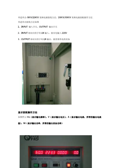
单进单出接线方法如图
1、INPUT输入开关,OUTPUT输出开关
2、INPUT相对应的字母LN输入,接市电输入220V
3、OUTPUT相对应的字母LN输出,接需要供电的设备
显示面板操作方法
如图所示Hz(显示输出频率),V(显示输出电压),A(显示输出电流,所带的输出电流值),W(显示输出功率,所带的输出设备功率)
1、绿色长方形为开机启动键(打开输入开关,过30秒再按启动键)
2、红色长方形为复位键(1.比如关机时,可按此键后在关输入开关和输出开关。
2.使用中出现报警可按红色长方形再按绿色长方形可以正常工作)
3、拔式按键为可调输出频率,所显示在面板上面的Hz位置。
4、红色正方形加盖为高低档,高档时灯亮(0-300V),低档时灯不亮(0-150V)。
5、数字旋钮调输出电压,所显示在面板上面的V位置。
设备基本说明4.1.1.电源:●将380V的三根火线直接与调频电源的“输入”连接。
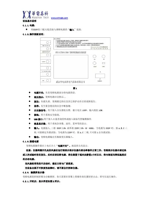
4.1.2.操作面板说明:图1●电源开关:负责变频电源部分的电源供给。
●高压指示:变频电源启动指示,。
●复位:负载失谐、变频源过热以及其它保护动作后的故障复位。
●急停:发生紧急情况的应急中断按键。
●分压器信号:用于接入分压器低压臂,最大电压100V,输入阻抗10M。
●接地:用于系统安全接地。
●USB接口:用于接入U盘查询资料或接入鼠标代替触摸操作.●液晶显示器:用于系统各参数、波形、菜单等的显示。
●输入:电源接入,三相 380V±5% 或单相220V±5% 45~65Hz,当电源为380V时,接A,B,C三相,可做额定负载试验;当电源为220V时,接A,C二相,只可做1/2负载试验。
●输出:变频电源输出至激励变压器输入。
4.1.3.接通电源变频电源操作箱在上电后合上“电源开关”,液晶屏点亮显示。
注意:仪器两侧开孔处的风扇在运行则表示表示仪器内部功率器件正常工作。
否则表示仪器内部过热或上次试验时没有复位。
此时应该切断电源,将仪器置于通风处静置1小时左右,待内部适当降低温度后再启动电源。
当风扇经常性的不启动时,建议立即与厂家联系。
当设备出现不可恢复性故障时,请不要自行拆卸仪器。
4.2.0. 触摸屏显示器:变频电源的控制屏幕为全触摸屏,你只需要在屏幕上要操作的位置轻轻点击,即可以进行操作。
4.2.1.开机后,显示界面如图2所示。
图24.2.2.试验参数配置:在每次试验前必须正确设置当次试验的各种参数!点击“参数配置”后,显示界面如图3所示。
图3●起始频率:选择自动调谐时的启动频率,下限频率最高为20Hz,上限频率最低为200Hz。
●终止频率:选择自动调谐时的结尾频率,下限频率最高为100Hz,上限频率最低为300Hz。
1.设置"起始频率"不可高于"终止频率"。
2.当第一次试验时建议采用30Hz~300Hz进行扫描。

APS5000A系列交流变频电源使用说明书版本:01目录第一章安全规定 (5)1.1安全须知 (5)1.2维护和保养 (5)第二章安装要点 (6)2.1拆封和检查 (6)2.2使用前的准备 (6)2.3储存和运输 (7)第三章技术规格 (8)第四章操作面板介绍 (9)4.1前面板说明 (9)4.2后面板说明 (10)第五章操作说明 (11)第六章附录资料 (14)6.1故障检修 (14)6.2串行口通讯失败的检查 (14)6.3产品维护 (14)6.4R S232通讯说明 (15)第一章安全规定使用前应该注意的规定和事项!!!安全标志高电压警告符号。
高压危险符号。
机体接地符号。
接地符号1.1 安全须知·使用本交流变频电源前,请先完整阅读本操作说明,并充分了解本机所使用的安全标志,以策安全.·在开启本机的输入电源开关前,请先选择正确的输入电压规格.为防止意外伤害或死亡发生,必须由专业人员连接各输入或输出线,在搬移和使用机器时,请务必先观察清楚,然后再进行操作.1.2 维护和保养使用者的维护为了防止触电的发生,请不要掀开仪器的盖子。
本仪器内部所有的零件绝对不需使用者维护。
如果仪器有异常情况发生,请寻求我公司或其指定的经销商给予维护。
所附的线路和方块图只供参考之用。
定期维护交流电源供应器、输入电源线各相关附件等每年至少要仔细检验和校验一次,以保护使用者的安全和仪器的精确性。
使用者的修改用者不得自行更改机器的线路或零件,如被更改,机器保质期则自动失效并且我公司不负责任。
使用未经本公司认可的零件或附件也不给予保证。
如发现送回检修的机器被更改,我公司会将机器的电路或零件修复回原来设计的状态,并收取修护费用。
第二章 安装要点产品的拆封、检查、使用前的准备、和储存等的规则。
2.1 拆封和检查1. 打开交流变频电源的包装,请检查随机附件,附件:1.说明书一本.2.合格证一份。
3.电源线一条。
2. 本产品包装在一个用珍珠棉保护的包装箱内,客户如果收到包装箱有破损时,请检查机器的外观是否有无变形、刮伤、或面板损坏等。

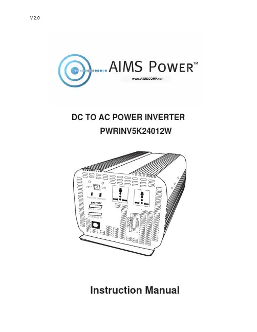
DC TO AC POWER INVERTER PWRINV5K24012WInstruction ManualIntroductionThe AIMS Power 5000 Watt inverter is the most advanced line of mobile DC to AC power systems available. This model is used in a wide range of applications including back up power for remote homes, off-grid systems, RVs, boats, commercial vehicles and mobile businesses. The 5000 Watt 240 Volt AC, 12 Volt DC inverter will operate most pumps, motors, and tools requiring 240V. This inverter only puts on 240 VAC single phase.To get the most out of the power inverter, it must be installed and used properly. Readthe instructions in this manual before installing and using this model.FUNCTIONSFRONT VIEWA. On/Off switch: Leave in the OFF position during installation.B. Over temperature indicator: Lights when inverter protects itself against overheating. Invertershuts down while indicator is on. Inverter will restart automatically and indicator will turn off when the inverter cools.C. Over load indicator: Lights when inverter shuts down because of overload. Indicator will turn offand inverter will restart when overload is removed.D. Bar meters: Displays battery voltage and current. Current should be in the green zone forcontinuous operation. The inverter will operate for several minutes when the current is in the yellow zone. Operation with battery voltage or current in the red zone of a meter will result in protective shutdown of inverter.E. AC outlets: Maximum recommended output per outlet is 1500W. Use AC direct connectterminal block for full 5000 watts.F. Remote port: Used with remote switch to turn inverter ON/OFF (sold separately).G. AC terminal block: Hard wire block providing inverter's full power.E: AC outletsD: Bar meters B: Over temperature indicator A: On/Off switchC: Over load indicator F: Remote PortG: AC terminal blockREAR VIEWA: Fan: Do not obstruct, allow at least 12 inch for air flow.B: Battery terminals: Connect to 12V battery (s) or other DC power source. "+" is positive & " - " isnegative. Reverse polarity connection will blow internal fuse and may damage inverter permanently. Make sure you check your input voltage and do not REVERSE POLARITY! This will void the warranty. C: Chassis ground lug: Connect to earth ground or to vehicle chassis using #8 AWG wire. Warning! Operation of the inverter without a proper ground connection may result in an electrical safety hazard.QUICK HOOK-UP AND TESTINGIf you would like to quickly hook-up the power inverter and check its performance before going ahead with your installation, please follow these guidelines:1. Unpack and inspect the power inverter, check to see that the power switch is in the OFF position.2. Before you connect the battery cables, make sure the power switch is in the off position. Connect Red (+) battery cable to Red (+) inverter terminal. Connect Black (-) battery cable to Black (-) inverter terminal. Connect Red (+) battery cable to Red (+) battery terminal. Connect Black (-) battery cable to Black (-) battery terminal. Alligator clamp cables may be used but only to connect to the battery. Do not use clamps on inverter terminals. Alligator clamps are not a permanent solution. You may see a spark during connection. Do not reverse the polarity. This may damage the inverter and void warranty. Caution! Loosely tightened connectors result in excessive voltage drop and may cause overheated wires and melted insulation. Reverse polarity connection will blow a fuse in inverter and may permanently damage the inverter. Damage caused by reverse polarity connection is not covered by our warranty. Warning! You may observe a spark when you make this connection since current may flow to charge capacitors in the power inverter. Do not make this connection in the presence of flammable fumes, as explosion or fire may result.3. Set the power switch to the on position. Check the meters and indicators on the front panel of the inverter. The voltage bar graph should indicate 11 to 14 volts depending on the voltage of the power source. If it does not, check your power source and the connections to inverter.A: FanB: Battery terminal (+)B: Battery terminal (-)C: Chassis groundingThe other indicators should be off.4. Set power inverter switch to the OFF position, the indicator l ights may blink and theinternal alarm may sound momentarily. This is normal. Plug the test load into the ACreceptacle on the front panel of the inverter. Leave the test load switch off.5. Set power inverter switch to the ON position and turn the test load on, the inverter shouldsupply power to the load. If you plan to measure the true output R.M.S. voltage of inverter, ameter such as FLUKE 87A, BACKMAN 4410 or TRIPLETT 4200 must be used.INSTALLATION1. Where to installThe power inverter should be installed in a location that meets the following requirements:a. Dry - Do not allow water to drip or splash onto the inverter.b. Cool - Ambient air temperature should be between 0°C and 40°C, the cooler the better when operating in this rangec. Ventilation - Allow at least 12 inches of clearance around the inverter for air flow. Ensure the ventilation openings on the rear and bottom of the unit are not obstructed.d. Safety - Do not install the inverter in the same compartment as batteries or in any compartment capable of storing flammable liquids such as gasoline.2. CablesDC to AC inverters require high amperage/low voltage DC power to low amperage/high voltage AC power. To operate properly, connect inverter DC input terminals direct to battery with heaviest wire available see chart below:12 Volt Model: 1 x set of 4/0 AWG (1 red + 1black) Recommended: 1ANL500KIT-500Amp fuse kit24 Volt Model: 1 x set of 1/0 AWG (1 red + 1black) Recommended: 1ANL300KIT-300Amp fuse kit36 Volt Model: 1 x set of 4 AWG (1 red + 1black) Recommended: 1ANL150KIT-150Amp fuse kit48 Volt Model: 1 x set of 6 AWG (1 red + 1black) Recommended: 1ANL150KIT-150Amp fuse kitBattery Cables InstallationWhen connecting the AC inverter to the battery terminals, it is important to connect the "+" wire to the "+" terminal and the wire to the"-" wire to the “-“ terminal. Do NOT reverse the polarity. It will void the warranty. Make sure you connect negative to negative and positive to positive.Red (+)Black (-)REDBLACKCaution!DO NOT allow the wires to cross or touch each other. Install the cables facing away from each other and screw tightly. When connecting the battery cables to the terminals of the inverter, make sure they do not touch the case.3. GroundingThe power inverter has a lug on the rear panel marked "chassis ground" This is to connect the chassis of the power inverter to the ground.The ground terminals in the AC outlets on the front panel of the inverter are also connected to the ground lug.The chassis ground lug must be connected to a grounding point, which will vary depending on where the power inverter is installed. In a vehicle, connect the chassis ground to the chassis of the vehicle. In a boat, connect to the boat's grounding systems in a fixed location, connect the chassis ground lug to an earth point, which will vary depending on where the power inverter is installed.The neutral (common)conductor of the power inverter AC output circuit is connected to the chassis ground. Therefore, when the chassis is connected to ground, the neutral conductor will also be grounded.This conforms to national electrical code requirements that separately derived AC sources (such as inverters and generators) have their neutral tied to ground in the same way that the neutral conductor from the utility line is tied to ground at the AC breaker panel.Caution! The Negative DC input of the power inverter is connected to the chassis. DO not install the power inverter in a positive ground DC system. A positive ground DC system has the positive terminal of the battery connected to the chassis of the vehicle or to the grounding point.Warning! Do not operate the power inverter without connecting it to ground. Electrical shock hazard may result.OPERATIONTo operate the power inverter, turn it on using the ON/OFF switch on the front panel. The power inverter is now ready to deliver AC power to your loads. If you are operating several loads from the power inverter, turn on separately after the inverter has been turned on. This will ensure that the power inverter does not deliver starting currents to all of the loads at once.1. Controls and indicatorsThe ON/OFF switch turns the control circuit in the power inverter on and off. It does not disconnect power from the power inverter.When the switch is in the OFF position, the power inverter draws no current from battery. When the switch is in the ON position but with no load, the power inverter draws less than 450 mA.2. Battery voltage indicatorThe battery voltage bar graph indicates the voltage at the input terminals of the power inverter. At low input current, this voltage is very close to the battery voltage. At high input current, this voltage will be lower than the battery voltage because of the voltage drop across the cable and connections.Ideally, the voltage should remain in the green area of the bar graph. If the voltage goes into the red area at top or bottom of the graph, inverter may shut-down.3. Battery current indicatorThe battery current bar graph indicates the current drawn from the battery by the power inverter, it will not indicate current by other loads also connected to the battery. The indicator only displays DC volts and amps.For long term operation, the current should be in the green area of the bar graph. Short term operation is possible with current in the orange area. If the current rises to the red area, the inverter will reduce its output voltage to protect itself.4. Over temp indicatorThe over temp indicator indicates that the power inverter has shut itself down because it has become overheated. The power inverter may overheat because it has been operated at power levels above its rating, or because it has been installed in a location which does not allow it to dissipate heat properly.5. Over load indicatorThe over load indicator indicates that the power inverter has shut itself down because its output circuit has been short circuited or drastically overloaded. Switch the ON/OFF to OFF, correct the fault condition, and then switch the ON/OFF back to ON.THINGS TO CONSIDER REGARDING THE LOADThe 5000W inverter will operate most AC loads within its power rating. When determining whether a microwave oven can be operated by the 5000W inverter, remember that the power commonly advertised for microwave ovens is the cooking power (the power delivered to the food) not the power actually consumed by the microwave oven. The microwave oven will consume 40% to 100% more than its advertised cooking power. Check the rating sticker on the back of the oven to determine its actual power draw. The 5000W inverter will operate small microwave ovens (0.2 to 0.3 cubic foot capacity) that draw is about 1700 watts.Some induction motors used in refrigerators, freezers, pumps, and other motor operated equipment require very high surge currents to start. The power inverter may not be able to start some of these appliances even though their rated current draw is within the rating of the power inverter.If a motor refuses to start, observe the battery voltage indicator while trying to start the motor. If the battery voltage indicator drops below 10.5V DC while inverter is attempting to start the motor, this may be why the motor won't start.Make sure that the battery connections are good and that the battery is fully charged. If the connections are good and the battery to is charged, but the voltage still drops below 11 volts, you may need a larger battery or larger battery bank.INPUT VOLTAGEThe power inverter will operate from input voltage ranging from 10V-16V. If the voltage drops below input range, an audible low battery warning will sound and the voltage indicator will be in the lower red zone. The power inverter will shut down if the input voltage drops below 10V, or 20V, or 30V, or 40V +/- .5V depending on model. This protects your battery from being over discharged.The power inverter will also shut down if the input voltage exceeds 17V +\-.5V. This protects the inverter against excessive input voltage.The voltage indicator will be in the upper red zone. Although the power inverter incorporates protection against over voltage, the inverter is at risk of permanent damage if the input voltage is allowed to exceed 17V +\-.5V depending on model.TROUBLESHOOTINGmon problemsa. Buzz in audio systems:Some inexpensive stereo systems and radios will emit a buzzing noise from their loudspeakers when operated from the power inverter. This is because the power supply in the device does not adequately filter the modified sine wave produced by the power inverter. The only solution is to use a sound system that incorporates a higher quality power supply.b. Television interference:Operation of the power inverter can interfere with television reception on some channels. If this situation occurs, the following steps may help to alleviate the problem.-Make sure that the chassis ground lug on the back of the power inverter is solidly connected to the ground system of your vehicle, boat or home.-Do not operate high power loads with the power inverter while watching television.-Make sure that the antenna feeding your television provides an adequate ("snow free") signal and that you are using good quality cable between the antenna and the television.-Move the television as far away from the power inverter as possible.-Keep the cables between the battery and the power inverter as short as possible and twist them together with about 2 to 3 twists per foot. This minimizes radiated interference from the cables.SPECIFICATIONSAIMS Corp., Inc. dba AIMS Power Warranty Instructions:This product is designed using the most modern digital technology and under very strict quality controland testing guidelines. If, however, you feel this product is not performing as it should, please contact us:**************************(775)359-6703We will do our best to resolve your concerns. If the product needs repair or replacement, make sure to keep your receipt/invoice, as that will need to be sent back along with the package and RMA# prepaid to AIMS. You have a full 1 year warranty from date of purchase.This warranty is valid worldwide with the exception that freight and duty charges incurred outside the contiguous 48 United States will be prepaid by customer.Except as provided above, AIMS makes no warranty of any kind, express or implied, including without limitation the implied warranties of merchantability and fitness for a particular purpose. In no event shall AIMS be liable for indirect, special or consequential damages. This warranty only applies to AIMS Power branded products. All other name brand products are warranted by and according to their respective manufacturer. Please do not attempt to return non-AIMS Power branded products to AIMS Power.For additional products such as:-Modified sine wave inverters-Pure sine wave inverters-Low Frequency Inverters-Solar Charge Controllers-Micro Grid Tied Inverters-Inverter Chargers and Automatic transfer switches-Converters DC-DC-Custom cut cables-Batteries-Solar Panels & RacksPlease visit our web site: Tofindoutwheretobuyanyofourproducts,youmayalsoe-mail:************************(775)359-6703.。
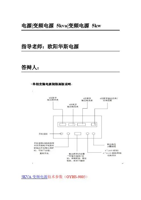
电源|变频电源5kva|变频电源5kw 指导老师:欧阳华斯电源答辩人:5KVA变频电源技术参数(OYHS-9805)产品共同特点输出电压:0-300V连续可调输出频率:60HZ,50HZ,40-499.9HZ连续可调超臷能力强,瞬间电流可承受三倍额定电流故障时一键停机功能,反应速度快,反应时间在2ms以内具有过流,过压,过温,短路,过载等多重保护及报警功能高精度的稳频稳压功能,快速调节电压,频率主要元器件均采用原装进口品牌,品质可靠单进单出变频电源技术参数型号(OYHS)OYHS-9805输出容量(5KVA)5KVA电路方式IGBT/SPWM脉宽调制方式交流输入相数单相波形SINEWAWE电压220V±15%频率波动范围50HZ or60HZ±10%功率因数﹥0.9交流输出相数单相波形SINE WAVE低档电压0-150V高档电压0-300V频率60HZ,50HZ,40-499.9HZ连续可调频率稳定率≤0.01%低档最大电流(A)42A(0-150V)高档最大电流(A)21A(150-300V)整机性能电源稳压率﹤1%负载稳压率﹤1%波形失真度﹤1%效率﹥90%反应时间≤2ms波峰因子3:1保护装置具有过压,过流,超载,输入欠压,过高温,短路等多重保护显示显示介面数位式LED显示电压4位数,数位电压表,解析度0.1V电流4位数,数位电流表,解析度0.1A功率4位数,数位瓦特表频率4位数,数位频率表环境及其它冷却装置高速变频风扇冷却,强制冷风工作温度-10℃to50℃相对湿度0~90%(非凝结状态)海拔高度≤1500m重量(KG)70尺寸(H*D*W)mm600*530*350注:1以上尺寸不含脚输高度2可根据顾客要求规格特别定制3本公司产品规格不断研发改进,规格若有变更,恕不另行通知。

HZBP-III 变频电源使用手册武汉合众电气欢迎使用武汉市合众电气设备制造有限公司产品尊敬的顾客感谢您使用本公司的产品。
在您初次使用设备前,请您详细地阅读本使用说明书,将可帮助您熟练地使用我公司设备。
我们的宗旨是不断地改进和完善公司的产品,因此您所使用的设备可能与使用说明书有少许的差别。
如果有改动的话,我们会用附页方式告知,敬请谅解!您有不清楚之处,请与公司售后服务部联络,我们定会满足您的要求。
由于试验设备均有可能带电压,您在插拔测试线、电源插座时,会产生电火花,小心电击,避免触电危险,注意人身安全!◆慎重保证本公司生产的产品,在发货之日起三个月内,如产品出现缺陷,实行包换。
三年内如产品出现缺陷,实行免费维修。
三年以上如产品出现缺陷,实行有偿终身维修。
如有合同约定的除外。
◆安全要求请阅读下列安全注意事项,以免人身伤害,并防止本产品或与其相连接的任何其它产品受到损坏。
为了避免可能发生的危险,本产品只可在规定的范围内使用。
只有合格的技术人员才可执行维修。
—防止火灾或人身伤害使用适当的电源线。
只可使用本产品专用、并且符合本产品规格的电源线。
正确地连接和断开。
当设备连线处联机状态时,请勿随意连接或断开测试导线。
产品接地。
本产品除通过电源线接地导线接地外,产品外壳的接地柱必欢迎使用武汉市合众电气设备制造有限公司产品须接地。
为了防止电击,接地导体必须与地面相连。
在与本产品做联机试验前,应确保本产品已正确接地。
注意所有终端的额定值。
为了防止火灾或电击危险,请注意本产品的所有额定值和标记。
在对本产品进行连接之前,请阅读本产品使用说明书,以便进一步了解有关额定值的信息。
请勿在无产品盖板时操作。
如盖板或面板已卸下,请勿操作本产品。
使用适当的保险丝。
只可使用符合本产品规定类型和额定值的保险丝。
避免接触裸露电路和带电金属。
产品有电时,请勿触摸裸露的接点和部位。
在有可疑的故障时,请勿操作。
如怀疑本产品有损坏,请本公司维修人员进行检查,切勿继续操作。
变频器配线部分,分为主回路和控制回路。
用户可将外壳的盖子掀开,此时可看到主回路端子和回路端子,用户必须依照下列的配线回路准确连接。
备注:(1)如果只有dcm端子,则acm端子等效于dcm端子。
(2)am端子等效于fm端子(am为可选端子)。
三、操作及运行1、操作说明(1)键盘说明(2)状态提示灯功能hz:当led显示内容为频率数据时,该指示灯亮。
i:当led显示内容为电流数据时,该指示灯亮。
fwd:当变频器处于正转运行时,该指示灯亮。
rev:当变频器处于反转运行时,该指示灯亮。
(3)监视运行参数变频器在运行过程中,按一次“data”键,再按“▲”或“▼”键选择观看运行电流或运行频率。
hz灯亮表示频率,i灯亮表示电流。
(4)查看故障记录变频器在运行过程中或待机状态下,按两次“prgm”键,再按“▲”或“▼”键可逐次观看最近4次故障记录。
观看完后按“data”键,变频器复位。
(5)参数修改步骤变频器在待机状态下:步骤1:按“prgm”键,变频器显示“fxxx”,“xxx”为参数号。
步骤4:按“▲”或“▼”键修改该参数值,按“stop/reset”键可以移动光标位置。
步骤5:按“rd/wt”键把数值设定。
如欲修改其它参数,请重复步骤1~5即可。
备注:要修改re/wt类型的参数时必须先把f096设为“1”。
2、操作范例(1)修改参数(将f002的参数值从10s改为5s)。
变频器通电后,键盘显示“0.00”,按一次“prgm”键,键盘显示“f000”;按“▲”键调到“f002”,按一次“rd/wt”键,读出该参数内容,键盘显示“10.0”,按“▼”键把“10”改为“5”,在按一次“ed/wt”键设定,然后按“data”键即可。
(2)变频器参数初始化变频器通电后,键盘显示“0.00”,按一次“prgm”键,键盘显示“f000”,然后按“▲”键把“f000”调到“f094”,再按一次“rd/wt”键,键盘显示“0”,按“▲”键改为“1”,按“rd/wt”键设定,再按两次“prgm”键,键盘显示“0.--”,然后在按一次“stop/reset”键,变频器开始初始化。
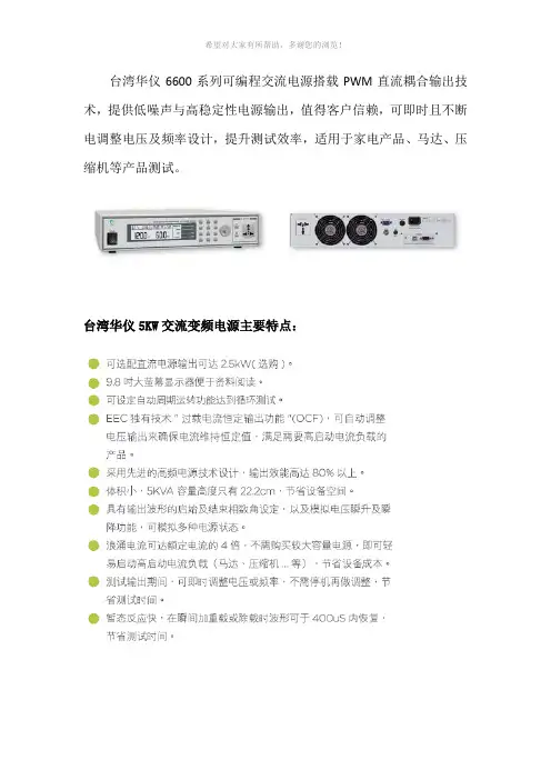
台湾华仪6600系列可编程交流电源搭载PWM直流耦合输出技术,提供低噪声与高稳定性电源输出,值得客户信赖,可即时且不断电调整电压及频率设计,提升测试效率,适用于家电产品、马达、压缩机等产品测试。
台湾华仪5KW交流变频电源主要特点:
华仪6600系列交流变频电源配置要求:
华仪6600系列交流变频电源规格表:
华仪6600系列交流变频电源型号:
1、6605 AC电源,0-300V/40-500Hz(500VA);
2、6610 AC电源,0-300V/40-500Hz(1KVA);
3、6620 AC电源,0-300V/40-500Hz(2KVA);
4、6630 AC电源,0-300V/40-500Hz(3KVA);
5、6650 AC电源,0-300V/40-500Hz(5KVA);
台湾华仪6600系列交流变频电源选购功能:
深圳市育创科技有限公司致力于从事仪器仪表的销售、系统集成销售及售后服务。
在EMC、光伏逆变器测试系统、新能源、动力电池、充电桩、汽车电子、变频器测试系统、电力测功试验台、电源自动化测试系统、电动车测试系统、电池充放电测试系统、安规测试系统、电磁兼容测试方案、嵌入式电路、温度测量、微波射频、安规测试系统、总线分析等方面为客户提供完善的解决方案及产品。
公司用高品质、真服务帮助用户提高工作效率和能力,通过公司全体员工不懈的努力,已经成为业界具影响力的仪器仪表销售公司。
凭借着良好的信誉和强大的技术实力,在激烈的竞争市场中不断的发展和完善,成为众多企业、高校在生产、研发、教学等工作中的得力合作伙伴,并为客户提供比较新的测试咨询以及较佳的测试配套解决方案。
RK5000 变频电源操作指导书
操作说明
1.使用前请先检视设备开关之完整性,并旋转面板上各种功能旋钮,检视是否有松动或过紧之状况。
2.先将电源开关置于『OFF』之位置。
3.为了确保设备之安全,请于接上输入电源前,再次确定输入电压规格是否正确。
4.打开设备之输入电源开关,经过约20秒后,蜂鸣器告警声响起,待按一下面板之上『RESST』开关后,此时才供应输出电压(缓机启动装置)。
5.选择输出频率:可任意切换所需之输出频率(不必关机),但请先关闭负载设备。
固定频率输出:直接切换至面板上之指示值,显示表上之频率值即为输出频率。
可调频率输出:切换至『V AR』,微调V AR(可调频率)旋钮,即可调至所需之输出频率。
例如欲输出55HZ之频率,则先选择开关切换至『V AR』,再微调V AR(可调频率)旋钮,调至频率显示表上之频率值为『55』即可。
6.标准电压调整:微调标准电压输出微调旋钮,即可调得所需之输出电压值。
7.以上步骤检视无误后,可将负载设备接上变频电源输出插座,以资使用。
附注:(1)本机含有输出超载及短路保护电路。
故发生输出超载或短路时,保护电路立即切断输出电源,蜂鸣器并发出警报声。
此时请先将输出所接负载设备关闭,再按一下面板上之『REST』开关解除警报,警报声停止后确认输出电压是否正常供应,确认无误后再开启负载。
(2)『注意』!如需做『HI/LO电压选择开关』切换时,请将所接负载设备关闭,再将变频电源之输出保护开关关闭后,始可进行切换。
(3)『注意』!如需400HZ频率或解除400HZ频率,请先将负载关闭后再进行切换。
5k不间断电源使⽤⼿册卧式新DL系列5K/10K不间断电源说明书杭州伊普通讯技术有限公司86604922⼀、简介1.1 系统概述DL系列UPS是⼀种采⽤国际上先进、成熟的进⼝机芯并采⽤专利的切换技术(专利号ZL200320122305.7)组合⽣产的电⼒专⽤在线式正弦波不间断供电系统。
它具有体积⼩、重量轻、效率⾼、运⾏可靠(平均⽆故障间隔时间不⼩于10万⼩时)的特点,可以为您的精密设备提供可靠、优质的交流电源,其适⽤范围⼴泛,从电脑设备、通信系统、电⼒⾃动化控制设备到⽆⼈值守的变电站都可以使⽤。
由于它的交直流在线零切换输出设计,⽆论是市电异常,还是市电正常,设备都是经过逆变向负载供电,它的输出始终是稳频、稳压的220V的纯正弦波交流电压,真正实现了不间断⼯作。
同时由于拥有单⽚机的完善检测和保护功能,以及采⽤先进的逐⼀脉冲过流检测的逆变技术,使整机具有抗⼲扰能⼒强、稳频稳压精度⾼、失真度⼩、效率⾼、具有强⼤的通讯远程管理功能,是电⼒专⽤UPS更新换代的⾸选产品。
采⽤⾼性能的DSP微处理器对UPS的运⾏⼯作进⾏实时闭环控制,直接参与控制内部的各重要参数,使得UPS始终处于最佳的⼯作状态,⼤⼤提⾼了UPS整机的各项性能。
现有的全数字化UPS能实时跟踪并修正输出纯正的正弦波,使交流输出中的直流分量等于零。
这是传统的数模组合的UPS所难以达到的。
由于采⽤了⾼性能的微处理器对UPS的运⾏⼯作进⾏实时闭环控制,使得所有的初始脉冲采⽤了缓启动,并且提⾼了UPS内部正负电源精度±0.5%,降低了总线电压,进⼀步减⼩了器件⼯作时的应⼒,⼤⼤延长了整机寿命。
DL系列UPS提供多种检测⽅式,包括⼀个RS232,⼀个可选择的Netmate⽹络适配器,它是UPS与⽹络沟通的桥梁。
内建完善的TCP/IP⽹络功能模块,⽀持SNMP、HTTP、Telnet、TCP、UDP、ARP、ICMP、DNS、SMTP、DHTP、TFTP等⽹络协议。
5KW 数位感应机使用说明书一.功能说明:1. 采用磁载率计算方法,可依不同材质自动选适合频率电流.2. 智能-3db调频调功方式.3. 安全最大输出380V/12A 7.5KW (以铸铁材质测试).4. 具锁频/ 锁流/ 自适应三种工作模式.5. 变频方式软启动,避免在线电流冲击.6. 可以二区选择加热方式模式,每组输出可以个别调整频率/电流/重置时间用以决定工作方式.7. 二区加热可外挂<50K可变电阻> 用以调整该区功率(锁流方式)限制.8. 二区加热各自有可设定<窗空间>光隔离输出,用以加热时连动其他设备.9. 具有线圈电感过大/过小,电流过大,电源谐波过大,在线功因过低,瞬间断电,三相缺相,过热保护.10. 自带隔离启动电源,可以直接调用.11. 显示面板,用以调整所有参数.二.5KW数字感应机规格表:规格备注说明;1.“最大安全输出功率”是感应机依据负载反馈所决定直,此值与工作频率与高频电流有关,其决定是以材质磁载特性所计算出来,其所输出功率非定数.最大以感应机安全输出为限制点.2.本机以磁载计算决定感应机安全输出,因此不同材质其对应感应输出功率会以所不同,其输出功率最大依序为铸铁>20号钢>45号钢>3铬钢>4铬钢>不锈钢.钳锅输出功率最大依序为铸铁锅.石墨锅.不锈钢锅(不导磁).三.接线说明:接线端子说明:1. 线圈为感应输出线圈点.2. 380V为三项380V电源输入.3. 机器上所引出24V(0.2ma)电源仅供机器启动电源用,勿作他用.4. 接点输出为光隔离开级对地输出,电流限制0.1A.5. 接点输入为光耦隔离输入,可以使用机器自代电源或外接DC/AC 10V-36V .6. 外接功率控制可变电组请使用50K奥姆,接点带电安装请注意.引线长度小于100cm并双绞.7. 控制输入/控制输出/可变电阻引线均不可与感应输出线过近或是绑一起.8.四. 调整说明1. 功能键有两种模式:a. 在感应动作时,可以按此键选择数字区显示内容如下.b. 常按三秒会进入感应机设定模式,再常按三秒则会退出设定模式并保存设定. (有关设定说明请参考设定说明下章). 2.上增键,有两种模式:a. 在感应动作时,按此键则屏幕显示-- -- 此时机器会暂停加热.b. 在设定模式下,此键式设定数值<上增>功能. 3.下减键,有两种模式:c. 在感应动作时,按<下减>键,机器会重新加热.d. 在设定模式下,此键式设定数值<下减>功能. 4. 锁流指示灯:此灯在感应机动作时将会点亮,到达锁流设定时以<闪烁>方式呈现. 5. 锁频指示灯:此灯在感应机动作时将会点亮,到达锁频设定时以<闪烁>方式呈现. 6.容区指示灯 :当此灯亮表示机器已达<感区><容区>接界点,此时机器会自动拉回感区运行,工作电流已达限制.此灯也是指是机器已达<谐振最高点>,此时如想提升工作电流,必须改变现圈圈数或是与负载对应距离.数值显示目前工作倒数计时数值显示目前工作频率数值显示目前高频电流五.设定说明:3. 设定完毕长按<设定键>退出设定,系统将自动永久保持设定.4. 感应机进入设定时,如感应机正处于工作,感应机将会被关闭.当设定退出后感应机将会重新动.5. 任何材质在设定范围内机器频出错导致无法启动,代表本机对被加热负载或是线圈无法运行,使用者可适当修正线圈感量/摆设,如无法解决机器错误警报则表示本机不适用此次加热项目.六.运行莹屏说明:当机器运行时将有两各(左上)指示灯会亮,数字显示则依功能指示显示,欲六.错误讯息说明:七.工作模式:1.锁频模式:锁频模式其输出频率为固定输出,使机器运行在固定频率下a. 使用此模式时,高频电流限制请设定为最大值68)b. 进入锁频模式时可以由<锁频指示灯>观看,如果呈现闪烁这代表机器已进入<锁频>模式.c. 这时电流将会随温度升高而往下降.适合带热慢速工作模式下的负载加热2.锁流模式;锁流模式其输出高频电流为固定输出,使机器运行在固定高频电流下:a. 使用此模式时,低频频率限制请设定为最小值88)b. 进入锁流模式时可以由<锁流指示灯>观看,如果呈现闪烁这代表机器已进入<锁流>模式.c. 这时电流将会随温度升高而升高.适合带热快速工作模式下的负载加热.3.自适应模式:也就是不锁频也不锁流模式下,机器工作以自适应负载下进行加热(适合非特定工件加热),但是前提是必须机器最大入电范围内(8KW最高允许入电为13.5A),可以如下方式设定.a. 将该输出组<低频频率限制>设定为88 (最低频率)b. 将该输出组<高频电流限制>设定为65 (最大高频电流输出)c. 设定自适应重置时间.d. 开机让其自适应加热.e. <锁流指示灯>与<锁频指示灯>均为恒亮.f. 机器运行到”最大安全高频输出功率”将将会有Er 2错误显示,2秒后自动锁住此加热状态持续加热.g. 当重置计时倒数到,机器将自动重新扫描抓取最佳工作.h. 自适应抓取可能会1-3次重新抓取状态.锁流模式电流八.安装注意事项:==== 请务必详读=====1. 感应线圈输出与电力输入比需夹端子并打上悍锡.2. 感应线圈请使用6mm 以上线径.3. 线圈至负载距离请大于15mm 以上.4. AC380V入点请加装25A以上空开.5. 机器上所引出24V(0.2ma)电源仅供机器启动电源用,勿作他用.6. 接点输出为光隔离开级对地输出,电流限制0.1A.7. 接点输入为光耦隔离输入,可以使用机器自代电源或外接DC/AC10V-36V .8. 外接功率控制可变电组请使用50K奥姆,接点带电安装请注意.引线长度小于100cm并双绞.9. 控制输入/控制输出/可变电阻引线均不可与感应输出现过近或是绑一起.10. 感应机必须有良好通风,如通风不良将导致感应机经常温度保护.11. 本机是以磁载概念对负载进行计算完成感应动作,因此本感应机可以安全在2KW-9.5KW输出运行,但是必须注意整机入电最大不宜超过12A,如感应机经常热保护[Er 1],请务必牺牲输出可以缓降若热保护次数.12. 多机装柜使用时请注意两机间必须有一适当距离(左右>5cm 上下10cm)以利散热以及配线.13.任何材质在设定范围内机器频出错导致无法启动,代表本机对被加热负载或是线圈无法运行,使用者可适当修正线圈感量/摆设,如无法解决表示本机不适用此次加热项目.14. 本机以磁载计算决定感应机安全输出,因此不同材质其对应感应输出功率会以所不同,其输出功率最大依序为铸铁>20号钢>45号钢>3铬钢>4铬钢>不锈钢.钳锅输出功率最大依序为铸铁锅.石墨锅.不锈钢锅(不导磁).九.十进制与十六进制参数对照表:1.频率表:2.十六进制与时十进制转换表11。
《变频使用说明》一、产品介绍变频器是一种能够根据负载需求自动调节电机的转速以达到节能、稳定运行的装置。
它通过改变电机输入电压的频率和幅值来调节电机转速,从而实现对电机负载的精确控制。
变频器具有节能、稳定运行、恒压恒流、提高智能化等优点,被广泛应用于工业生产中。
二、使用准备1.确认电源电压和频率与变频器的额定值相匹配;2.确保电源供电可靠,以防止意外断电导致设备损坏;3.变频器周围应保持通风良好,避免高温环境影响设备正常运行;4.根据实际需要调整变频器的参数设置,以满足不同负载的要求。
三、使用步骤1.打开变频器的电源开关,并确认显示屏上的电源指示灯亮起;2.检查变频器的各个连接端口,确保连接正确稳固;3.将变频器的输出端与电机连接,确保连接牢固;4.调整变频器的参数设置,根据实际负载要求调整频率、电压和转速等参数;5.按下启动按钮,观察电机的运行情况,如有异常现象及时停机检查;6.调整变频器的运行参数,使电机达到理想状态;7.定期检查变频器的散热器,清除灰尘等杂物,确保散热正常;8.关闭设备时,先停止电机运行,再关闭电源开关。
四、注意事项1.在使用变频器时,应遵循相关的操作规程和安全操作规定,确保人身安全;2.变频器具有高压电流,禁止在运行状态下进行拆卸和维修;3.在设备故障时及时停机排除故障,避免进一步损坏设备;4.避免超负荷运行,以免损坏电机和变频器;5.注意电机的绝缘状态,定期检查绝缘性能,确保安全;6.变频器具有一定的散热功率,避免在封闭空间中使用。
五、常见问题及处理方法1.变频器无法启动可能原因:电源故障、电机或变频器连接故障、参数设置错误处理方法:检查电源供电是否正常,检查连接是否正确,检查参数设置是否正确2.变频器工作不稳定可能原因:电源波动、负载突变、参数设置不合理处理方法:检查电源波动情况,调整参数设置,适应负载变化3.变频器发热过高可能原因:散热器堵塞、环境温度过高、负载过大处理方法:清除散热器上的杂物,降低环境温度,减少负载通过以上的《变频使用说明》,用户可以了解到如何正确地使用和操作变频器,避免不必要的损坏和事故,并能根据实际需求调整参数,使电机达到最佳的运行状态,实现节能和提高生产效率的目标。
变频电源使用说明书深圳市欧阳华斯电源有限公司目录◆注意事项◆产品简介◆面板图及功能说明◆安装说明◆配线线径参考表◆配线注意事项◆操作说明◆电气规格◆状况处理1、注意事项感谢您购买本公司产品,在使用前请务心详阅此手册,并请妥善保存。
机器搬运时请小心轻放,避免碰撞。
电源请依照电工法规及安装说明施工。
请依照操作说明指示步骤,依序操作。
请勿打开机盖,以避免触电及机器损坏。
请保持机器之乾净与清洁。
请勿将机器置於潮湿、闷热让阳光直射之处。
若有异常现象,请参阅“状况处理”程序。
2、产品介绍使用场所介绍:1.外销品测试:A、产品行销目的地使用电源模拟化。
B、规格之认定统一化。
C、无干扰促使产品功能进级化。
D、研发好帮手,各国电力测试随心所得电源国际化。
E、制程上无缺点的产品规格化。
2、品质认证:A、产品规格一致化,促进产业升级。
B、各国标准之认证标准电源。
C、纯净正弦波,电源建立标准之利器。
D、EMI/EMC安规测试标准电源。
3、精密度仪器设备的专用电源:A、高精度之仪器使用电源,能使各种功能完完整整的表现出来。
B、整厂设备输出,事前模拟,促进设备之全功能化。
C、制造无障碍设备的专属电源。
使用产品介绍:电脑(PC)空调设备监视器(Monitor)日光灯安定器测试电脑用直流电源供应器(SPS)各种电器用品变压器音响设备马达电器设备测试家用设备产品(冷气、冰箱、电视)冷气压缩机制造400HZ:军用设备机场设备通讯设备航太工业船舶及导弹设备专用电源3、面板图及功能说明单相变频电源规格面板说明4、面板图及功能说明三相变频电源规格面板说明5、变频电源外观说明(单相变频电源机型)1234121356789111415(三相变频电源机型)6、变频电源外观说明说明顺序由左至右,由上而下,逐步叙述之:1.输出频率指示表:数位式显示输出频率至小数点下一位。
2.输出电压指示表:数位式显示输出电压值。
3.负载电流指示表:数位式显示输出电流值。
变频电源使用操作手册操作步骤:1 、将所有输入、输出空开以及设备供电线路中的开关置于分断状态。
按照电气安装说明连接好变频电源输入、输出线缆。
!注意设备供电线路中的开关由客户自行提供、安装。
2 、为确保设备安全,再次确定输入电压是否在允许范围之内。
本机器具有缺相、过压、欠压保护。
电压允许范围380V±15%。
3 、将设备供电线路中的开关合闸。
4 、将输入空气开关合闸。
!注意此时变频电源已经上电,请参考“安全及注意事项”中的说明,注意安全用电!5 、观察显示面板显示是否正常,若正常则按下复位按钮,变频电源即进入启动状态,此时变频电源按照预设的电压和频率输出。
!注意若上电后显示面板无显示或显示不正常,请参照“异常处理”。
6 、若预设电压不是负载所需电压,请调节电压调节旋钮和频率切换旋钮,以使电源输出所需的电压及频率。
!注意若电压调节旋钮旋转到尽头后,仍未达到所需电压,请检查换挡按钮是否按下。
7 、变频电源启动后,请待机至少5分钟,使变频电源全面预热,以防接入负载之后工作在不稳定状态。
8 、观察变频电源空载运行参数是否正常,若正常则闭合输出空气开关,接通负载。
9、观察变频电源带载运行参数是否正常,若不正常则切断负载,进行相关检查及操作。
10 、关闭变频电源时,先断开输出空气开关,切断负载,再断开输入空气开关、设备供电线路中的开关,切断电源。
!注意对变频电源进行操作时,请务必按照操作说明实施相关操作,以防造成不必要的伤害及设备损坏!!注意变频电源在过载、过流、过热或短路保护时,保护电路会立即切断电源的输出,同时会有蜂鸣报警声。
此时请先断开负载,再按下复位按钮,报警声解除后待输出电压显示正常时,检查负载状况,确认无异常后,再重新接入负载。
!注意变频电源在缺相、过压、欠压保护时,保护电路会立即切断电源的输出,同时会有蜂鸣报警声。
此时请先断开负载,再按下复位按钮,若按动复位按钮机器无反应,报警声从无中断持续报警。