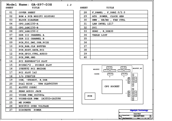
GA-Z97(H97)-HD3主板说明书
- 格式:pdf
- 大小:1.33 MB
- 文档页数:19

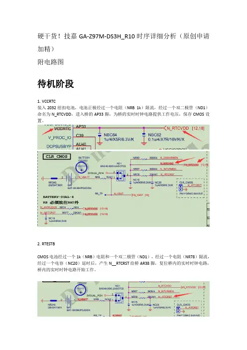
硬干货!技嘉GA-Z97M-DS3H_R10时序详细分析(原创申请加精)附电路图待机阶段1.VCCRTC装入2032纽扣电池,电池正极经过一个电阻(NRB 1k)限流,经过一个双二极管(ND1)命名为N_RTCVDD,进入桥的AP33脚,为桥的实时时钟电路提供工作电压,保存CMOS设置。
2.RTESTBCMOS电池经过一个1k(NRB)电阻和一个双二极管(ND1),经过一个电阻(NR78)限流,经过一个电容(NC20)延时后,产生N__RTCRST给桥AR38脚,复位桥内的实时时钟电路,桥内的实时时钟电路开始工作。
3.SRTCRSTBCMOS电池产生的N_RTCVDD电压,经过一个电阻NR77(20k)限流,和一个电容延时NC19(1u)后,产生N_SRTCRST信号送到桥的AR39脚,复位桥内部的ME模块。
4.INTRUDERBCMOS电池产生的N_RTCVDD电压经过一个电阻NR74(1M)送入桥的AR41脚,将入侵检测信号置高。
5.INTVRMENCMOS电池产生的N_RTCVDD电压经过一个电阻NR67(390k)送入桥的AV36脚开启桥内部的电压调节模组,也就是稳压器。
6.DSWODVRENCMOS电池产生的N_RTCVDD电压经过一个电阻NR90(390k)送入桥的AM41脚开启桥内部的ME电压调节模组。
7.32.768hz晶振桥得到VCCRTC供电和RTESTB后,实时时钟晶振起振,产生32.768hz的时钟信号,提供给桥RTC模块、SPI模块、和ME模块使用。
8.3VDUAL_PCH(待机主供电,插入ATX后产生)当插入ATX电源后,5VSB通过一个三端线性降压器(NQ9 L1117)降压为3VDUAL_PCH,为桥以及IO待机时提供供电。
经过一个电阻(OR8 0欧)更名为IT_VCCH,为IO提供待机电压。
当插入ATX电源后,取代纽扣电池为实时时钟电路供电。
9.VCCPDSW3_3(深度睡眠时桥供电)桥进入深度睡眠时的供电,由3VDUAL_PCH提供,此主板部分取消了深度睡眠功能,只要插入ATX电源后,几个主要的待机电压都就出现了,不受深度睡眠信号的控制。
ARM8060嵌入式主板说明书北京阿尔泰科技发展有限公司Beijing Art Technology Development Co.,Ltd.!安全须知电气方面安全性➢为避免可能的电击造成严重损害,在移动主板之前,请先将主板的电源切断。
➢当您要加入硬件设备到系统中或者要移除系统中的硬件设备时,请务必先连接该设备的信号线,然后再连接电源线。
➢请确定电源的电压设置已调整到所规定的电压标准值。
操作方面的安全性➢在您安装主板以及加入硬件设备之前,请务必详细阅读本手册所提供的相关信息。
➢在使用本产品之前,请确定所有的排线、电源线都正确地连接好。
若您发现有任何重大的瑕疵,请尽快联系我们或您的经销商。
➢为避免发生电气短路情形,请务必将所有没用到的螺丝、回形针及其它零件收好,不要遗留在主板上。
➢灰尘、湿气以及剧烈的温度变化都会影响主板的使用寿命,因此请尽量避免放置在这些地方。
➢当操作系统启动过程中,请勿断电,为避免损坏主板芯片➢系统运行过程中,防止静电,最好不要用手接触主板➢若在本产品使用上有任何的技术性问题,请和我们的技术支持人员联系。
目录目录11.产品简介11.1产品概述11.2 产品特点错误!未定义书签。
2产品特性72.1跳线说明72.2 外围设备接口连接82.3 软件特性错误!未定义书签。
3.电气参数及机械特性14附录A 订购信息15附录B 应用程序开发环境151.产品简介1.1产品概述ARM8060是北京阿尔泰科技发展有限公司基于Atmel公司ARM926EJ-S内核的AT91SAM9261处理器,结合PC104总线规范设计的一款具有极高性价比、结构和尺寸极其紧凑并且功耗极低的工业级嵌入式主板,其上运行嵌入式Linux 或WinCE操作系统,可以处理多种计算任务。
主板采用超低功耗嵌入式处理器,无风扇设计,超宽工作温度-20°C ~+70°C,低温工作性能优良,高温工作彻底解决了由于风扇可靠性而引起的故障。
AC97和HD 规范简介和前置音频接口的连接(不会搞前置音频的仔细看看,我转的累死了,麻烦不看也顶一下~绝对好贴!)引用地址:/b186090/d3*******.htm [复制│超文本复制]返回《AMDfans 》 关闭窗口01165694 U-boat发表于:06-07-06 00:20 [只看该作者]英特尔在AC97音频标准之后,又推出了HD(高保真)音频标准。
微软的新操作系统Vista 推出UAA 音频。
这些音频标准对机箱的前置音频面板和接口都有各自的规定。
主板的前置音频连接座也有变化。
本文就AC97和HD 的前置音频/麦克的接线方式作详细说明,供各位参考。
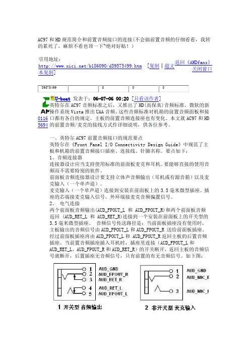
一、英特尔AC97前置音频接口的规范要点英特尔在《Front Panel I/O Connectivity Design Guide 》中规范了主板和机箱的前置音频接口插座、连接线、针脚名称。
要点如下:1、音频连接器连接器设计应当支持使用标准的前面板麦克和耳机。
要能够直接的使用音频而不需要特别的软件。
前面板音频连接器设计要支持立体声音频输出(耳机或有源音箱)以及麦克输入(一个单声道)。
麦克输入(一个单声道)连接到安装在前面板上的3.5毫米微型插座。
插座的芯端接麦克输入信号,外环端接麦克音频偏置信号。
2、 电气连接两个前面板音频输出(AUD_FPOUT_L 和 AUD_FPOUT_R)和两个前面板音频返回 (AUD_RET_L 和 AUD_RET_R)连接到一个安装在前面板上的开关型的3.5毫米微型插座。
音频信号传送路径是:当前面板插座没有使用时,主板输出的音频信号由AUD_FPOUT_L 和AUD_FPOUT_R 送给前面板插座。
经过前面板插座再由AUD_FPOUT_L 和 AUD_FPOUT_R 返回主板的后置音频插座。
当前置音频插座插入耳机时,插座里连接(AUD_FPOUT_L 和AUD_RET_L ,AUD_FPOUT_R 和AUD_RET_R )的开关断开,返回主板的音频信号就断开,后置插座无音频信号,只有前置的有无音频信号。
User GuideEVGA Z97 Classified Specs and Initial Installation(Part 1)- 1 -Table of ContentsBefore you Begin (3)Parts Not in the kit (4)Intentions of the kit (4)Motherboard Specifications (5)Unpacking and Parts Descriptions (7)Equipment (7)Hardware Installation (8)Component legend (8)PCI-E Slot Breakdown (9)Rear I/O Panel legend (10)Preparing the Motherboard (11)Installing the CPU (11)Installing the Cooling Device (12)Installing System Memory (DIMMs) (13)Compliance Information (14)- 2 -Before You Begin… Welcome to a new class of high performance motherboards that boast 4th and 5th Generation Intel® Core™ Processor compatibility. The Z97 platform takes you to anew level of performance and efficiency. We have refined the GUI BIOS interface, reimagined power VRM that focuses on efficiency, added MPCIE support and loadedwith features like 4-Way SLI, Creative Sound Core3D quad-core audio processor, Intel Gigabit LAN, native SATA 6G/USB 3.0 and more. All sitting on an 8 layer PCB to improve performance and efficiency.Did we also mention that this motherboard is designed for the overclocker? Built fromthe ground up to give you all the essentials that you need for overclocking, with a GUIBIOS that is focused on functionality, ultra high quality components and robust PCI-E3.0 and memory trace layout.With these features and more, it is clear that the EVGA Z97 motherboards areengineered to exceed the best.- 3 -Parts NOT in the KitThis kit contains all the hardware necessary to install and connect your newEVGA Z97 Classified Motherboard. However, it does NOT contain thefollowing items that must be purchased separately in order to make the systemfully functional and install an Operating System:Intel Socket 1150 ProcessorDDR3 System MemoryCPU Cooling DevicePCI Express Graphics CardPower SupplyHard Drive or SSDKeyboard / MouseMonitor(Optional) Optical DriveEVGA assumes you have purchased all the necessary parts needed to allow forproper system functionality. For a full list of supported CPUs on thismotherboard, please visit /support/motherboardIntentions of the KitThis kit provides you with the motherboard and all connecting cables necessaryto install the motherboard into a PC case.When replacing a motherboard in a PC case, you will need to reinstall anoperating system even though the current storage drive may already have oneinstalled.- 4 -MotherboardMotherboard SpecificationsSize:EATX form factor of 12 inches x 10.3 inchesMicroprocessor support:Intel Socket 1150 ProcessorOperating Systems:Supports Windows 8 / 7Contains Intel Z97 chipsetSystem Memory support:Supports Dual channel DDR3 up to 2666MHz+.Officially supports up to 32GB of DDR3 memory.USB 2.0 Ports:6x from Intel Z97 PCH – 4x external, 2x internalSupports hot plugSupports wake-up from S1 and S3 modeSupports USB 2.0 protocol up to a 480 Mbps transmission rateUSB 3.0 Ports:6x from Intel Z97 PCH – 4x external, 2x internalSupports transfer speeds up to 5GbpsBackwards compatible USB 2.0 and USB 1.1 supportSATA Ports:Intel Z97 PCH Controller6x SATA 3/6G (600 MB/s) data transfer rate- Support for RAID 0, RAID 1, RAID 0+1, RAID 5, AND RAID 10- Supports hot plug2x SATA3/6G Marvell 88E9182Onboard LAN:1x Intel i217 Gigabit Ethernet PHY1x Intel i210 Gigabit Ethernet MACSupports 10/100/1000 Mb/sec Ethernet- 5 -Onboard Audio:Creative Core3D Quad-Core Audio Processor (CA0132)Supports 6-channel (5.1) audioSupports Optical OutputPCI-E 3.0 Support:Low power consumption and power management featuresPower Functions:Supports ACPI (Advanced Configuration and Power Interface)Supports S0 (normal), S1 (power on suspend), S3 (suspend to RAM), S4 (Suspend to disk - depends on OS), and S5 (soft - off)Expansion Slots:5x PCI-E 16x slot 2x16/8, 1x8, 1x8/4, 1x81x PCI-E 1x slot1x Mini PCI-E/mSATA2x Mini Display Ports (on I/O Panel)- 6 -- 7 -Unpacking and Parts DescriptionsEquipmentThe following accessories are included with the EVGA Z97 Classified Motherboard:The EVGA Z97 Classified MotherboardThis PCI-E motherboard contains the Intel Z97 chipset.I/O ShieldInstalls in the system case to block radio frequencytransmissions, protect internal components from dust, foreign objects, and aids in proper airflow within the chassis.4x SATA 3G/6G Data CablesUsed to support the SATA protocol and each one connects a single drive to the motherboard.I/O CoverThis optional cover attaches to the PCB and covers the I/O areaInstallation CDContains drivers and software needed to setup the motherboard.User ManualThe user manual you are reading right now!Intel Z97 Classified MotherboardThe EVGA Z97 Classified Motherboard with the Intel Z97 and PCH Chipset. Figure 1 shows the motherboard and Figure 2 shows the back panel connectorsFIGURE 1. Z97 Classified Motherboard Layout- 8 -1. CPU Socket 1150 12. Debug LED / CPU Temp Monitor 23. Mini PCI-E/mSATA2. Intel Z97 Southbridge 13. CMOS Battery 24. Front Panel Audio Connector3. CPU Fan Header (1 amp PWM) 14. USB 3.0 Headers 25. EVGauge4. DDR3 Memory DIMM Slots 1-4 15. USB 2.0 Headers 26. Back Panel Connectors (Figure 2)5. 24-pin ATX power connector 16. CMOS Reset Button 27. 8 pin EPS Connector6. Fan Headers (1 amp DC) 17. Power Button 28. Supplemental PCI-E 6pin Power7. PCI-E Disable Dipswitches 18. Reset Button 29. GPU Link8. Intel Sata 6G Ports 19. PC Speaker 30. Probe It Header9. Marvell Sata 6G Ports 20. PCI-E Slot 16x/8x 31. BIOS Selector Switch10. ECP Header 21. PCI-E Slot 8x 32. Removable BIOS Chip11. Front Panel Connectors 22. PCI-E Slot 1xPCI-E Slot BreakdownPCI-E Lane DistributionPE1 – x16 (x8 if PE2 is used)PE2 – x16 (x8 if PE3 is used)PE3 – x8PE4 – x16 (x8 if PE6 is used)PE5 – x1PE6 – x8- 9 -- 10 -Figure 2. Chassis Rear Panel Connectors1. USB2.0 4. Intel i210 NIC 7. Optical Out2. USB3.05. Intel i217 NIC 8. Analog Audio Output Jacks3. BIOS/CMOS Reset6. Mini Display PortAnalog Audio Port Breakdown2/2.1 (Channel) 4.0/4.1 (Channel) 5.1 (6 Channel) Blue Line in Line In Line in Green Line Out/ Front Speaker/ Front Speaker/ Speaker Out Speaker+Sub Out Speaker+Sub Out Pink Mic InMic InMic InBlack Rear Speaker OutRear Speaker Out OrangeCenter/Voice channel- 11 -Preparing the MotherboardInstalling the CPUBe very careful when handling the CPU. Hold the processoronly by the edges and do not touch the bottom of theprocessor. Note: Use extreme caution when working with the CPU,not to damage any pins in the CPU socket on themotherboard!Use the following procedure to install the CPU onto the motherboard:Remove the plastic protective socket cover by pulling it straight up. Be sure not to damage any of the pinsinside the socket.Unhook the socket lever by pushing down and away from the socket.Pull the socket lever back and the load plate will lift. Open the load plate and make sure not to damage any of the pins inside the socket.Note:After removing the CPU socket cover, it is recommended to store it incase you ever need to transport your motherboard. If you ever remove theCPU, it is highly recommended to reinstall the socket cover.socket.Lower the processor straight down into the socket.Note: Make sure the CPU is fully seated and level inthe socket.Carefully lock the lever back into place.Installing the CPU Cooling DeviceThere are many different cooling devices that can be used with thismotherboard. Follow the instructions that come with your cooling assembly.- 12 -Installing System Memory (DIMMs)Your Z97 Classified has (4) 240-pin slots for DDR3 memory. These slotssupport 2GB, 4GB and 8GB DDR3 DIMMs. There must be at least onememory slot populated to ensure normal operation.maximum of 32GB of DDR3 and up to 2666MHz+ in dual channelconfiguration. It is required to populate slot 1 first. The board will notboot if slot 1 is not populated.Use the following procedure to install DIMMs. Note that there isonly one gap near the center of the DIMM slots. This slot matchesthe slot on the DIMM to ensure the component is installed properly.Unlock a DIMM slot by pressing the module clips on both sidesoutward.Align the memory module to the DIMM slot, and insert the modulevertically into the DIMM slot, pressing straight down to seat themodule. The plastic clips at top side of the DIMM slot automaticallylock the DIMM into the connector.Note: The memory controller on most Haswell and Broadwell CPUs runs at adefault frequency of 1600MHz. To achieve memory speeds above 1600+may require manual setting of the memory timings, frequency and voltagesand/or overclocking of the CPU.Refer to the memory manufacturer specifications for the recommendedmemory timings. For overclocking support you can visit our forums:/- 13 -Compliance InformationFCC Compliance InformationThis device complies with FCC Rules Part 15. Operation is subject to the following two conditions: (1) This device may notcause harmful interference, and (2) this device must accept any interference received, including interference that maycause undesired operation. This equipment has been tested and found to comply with the limits for a Class B digital device, pursuant to Part 15 of the FCC Rules. These limits are designed to provide reasonable protection against harmful interference in a residential installation. This equipment generates, uses and can radiate radio frequency energy and, ifnot installed and used in accordance with the manufacturer’s instructions, may cause harmful interference to radio communications. However, there is no guarantee that interference will not occur in a particular installation. If this equipment does cause harmful interference to radio or television reception, which can be determined by turning the equipment off and on, the user is encouraged to try to correct the interference by one or more of the following measures:(1) Increase the separation between the equipment and signal source, or (2) connect the equipment to an outlet on acircuit different from that to which the signal source is connected. Consult the dealer or an experienced computer technician for help. The use of shielded cables for connection of peripheral devices to the PC systems is required toensure compliance with FCC regulations. Changes or modifications to this unit not expressly approved by the party responsible for compliance could void the user’s authority to operate the equipment.CE Compliance InformationGeneric Radiation Interference Standard for Information Technology Equipment. (EN 55022: 2006, Class B), (EN 61000-3-2: 2006), (EN 61000-3-3: 1995 + A1: 2001 + A2: 2005). Warning: This is a Class B product. In a domestic environmentthis product may cause radio interference in which case the user may be required to take adequate measure. GenericImmunity Standard for Information Technology Equipment. (EN 55024: 1998 + A1: 2001 + A2: 2003).Trademark & Copyright Information2001-2014 EVGA Corp. EVGA, the EVGA logo and combinations thereof are trademarks of EVGA Corp. All brand names, company names, service marks, logos, and trademarks of the company, or its affiliates or licensors are trademarks or registered trademarks of the company or its subsidiaries, affiliates or licensors in the US and other countries. Other company, products and service names may be trademarks or service marks of others. EVGA reserves the right to terminate this license if there is a violation of its terms or default by the Original Purchaser. Upon termination, for any reason, all copies of Software and materials must be immediately returned to EVGA and the Original Purchaser shall beliable to CORP for any and all damages suffered as a result of the violation or default.Legal InformationAll material including but not limited to, text, data, design specifications, diagnostics, graphics, logos, reference boards,files, images, drawings, and software including this document and the software itself (together and separately) is owned, controlled by, licensed to, or used with permission by EVGA Corporation and is protected by copyright, trademark, andother intellectual property rights. All is being provided “as is”, EVGA Corporation makes no warranties, whether expressor implied, statutory or otherwise with respect to the materials and expressly disclaims all implied warranties of non-infringement, merchantability, and fitness for a particular purpose. In no event shall the liability of EVGA Corporation forclaims arising from the use of the materials by anyone exceed the original purchase price of the materials (or replacementof the materials at EVGA Corporation’s option). All information furnished is believed to be accurate and reliable. However,EVGA Corporation assumes no responsibility for the consequences of use of such information or for any infringement of patents or other rights of third parties that may result from its use, or use of the Software. No license is granted by implication or otherwise under any patent or patent rights of EVGA Corporation except as expressly provided herein. All specifications mentioned in this publication are subject to change without notice.Ver. 2- 14 -。
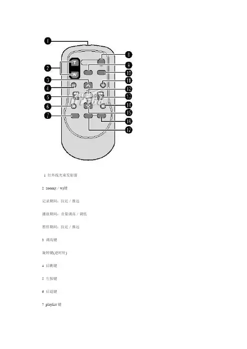
1 红外线光束发射窗2 zoom(t/w)键记录期间:拉近/推远播放期间:音量调高/调低暂停期间:拉近/推远3 调高键旋转键(逆时针)4 后跳键5 左按键6 后退键7 playlist键8 start/stop键9 snapshot键10 info键11 前跳键12 play/pause键13 右按键14 下一步键15 调低键旋转键(顺时针)16 index键17 date键将芯线过滤器安装到音频电缆和直流电源线将芯线过滤器安装到音频电缆,该电缆用于将选购外部麦克风连接到摄像机上。
此外,请将芯线过滤器安装到直流电源线。
芯线过滤器用于降低干扰。
将带有芯线过滤器的电缆一端连接到摄像机。
液晶监视器上的指示记录视频和静像时1 选定的记录模式指示2 近拍模式指示3 近似变焦比4 抑制指示5 变焦指示6 聚焦辅助指示7 快门速度8 亮度/锐度控制指示9 电池指示10 日期/时间11 手动聚焦调整指示12 选定的记录媒体指示13 防摔保护指示([防摔保护]设为[关]时出现。
)14 效果模式指示16 白平衡指示17 光圈值(f值)18 led灯指示19 ±0:曝光调节指示20 光圈锁定指示仅记录视频时1 模式指示2 风声消除指示3 图像质量4 剩余时间5 计数器外部麦克风输入音量指示8 事件指示9 手振补偿指示([手振补偿]设为[关]时出现。
)仅在记录静像时1 模式指示2 iso 感光度(增益):设为[自动]时无指示。
3 聚焦指示4 图像像素5 图像质量剩余拍摄张数8 拍摄指示9 自拍定时指示仅在视频播放时1 模式指示2 p:播放列表播放指示(仅在播放播放列表时出现。
)3 图像质量4 播放模式5 计数器6 音量指示7 电池指示8 日期/时间9 选择媒体指示10 防摔保护指示([防摔保护]设为[关]时出现。
)11 效果模式指示12 画面切换效果指示在播放静像时1 模式指示2 文件夹/文件号码3 幻灯片放映指示4 电池指示5 日期/时间选择媒体指示防摔保护指示([防摔保护]设为[关]时出现。
GA-G41MT-D3P GA-G41MT-S2PLGA775主板支持Intel® Core™ 系列处理器/ Intel® Pentium®系列处理器/ Intel® Celeron®系列处理器使用手册Rev. 130112MSC-41MTS2P-1301RDec. 31, 2010Motherboard GA-G41MT-D3P/GA-G41MT-S2P Dec. 31, 2010Motherboard GA-G41MT-D3P/GA-G41MT-S2P版权责任声明产品版本辨识目录GA-G41MT-D3P/GA-G41MT-S2P主板配置图 (5)第一章硬件安装 (6)1-1 安装前的注意须知 (6)1-2 产品规格 (7)1-3 安装中央处理器及散热风扇 (9)1-3-1 安装中央处理器(CPU) (9)1-4 安装内存条 (10)1-4-1 双通道内存技术 (10)1-5 安装适配卡 (10)1-6 后方设备插座介绍 (11)1-7 插座及跳线介绍 (12)第二章BIOS 程序设定 (19)2-1 开机画面 (19)2-2 BIOS设定程序主画面 (19)2-3 MB Intelligent Tweaker(M.I.T.) (频率/电压控制) (20)2-4 Standard CMOS Features (标准CMOS设定) (26)2-5 Advanced BIOS Features (高级BIOS功能设定) (27)2-6 Advanced Chipset Features (高级芯片组功能设定) (28)2-7 Integrated Peripherals (集成外设) (29)2-8 Power Management Setup (省电功能设定) (31)2-9 PnP/PCI Configurations (即插即用与PCI程序设定) (32)2-10 PC Health Status (电脑健康状态) (33)2-11 Load Fail-Safe Defaults (载入最安全预设值) (34)2-12 Load Optimized Defaults (载入最佳化预设值) (34)2-13 Set Supervisor/User Password (设定管理员/用户密码) (35)2-14 Save & Exit Setup (储存设定值并结束设定程序) (35)2-15 Exit Without Saving (结束设定程序但不储存设定值) (36)第三章驱动程序安装 (36)3-1 芯片组驱动程序 (36)管理声明 (37)- 4 -LGA775 CPU插槽LGA775 CPU凹角CPU - 9 -SATA硬盘。
【华硕Z97评测】DIY新手说明书⑦别让主板规格冲昏头!前言:马上就要到年底了,相信一定有不少DIY爱好者已经准备好攒下来的私房钱,在年底装一台新电脑。
确实在年底这段时间,DIY市场整体价格应该是最后的低谷,毕竟到了春节期间不少商户各回各家,不少硬件都会出现断货的情况。
所以,如果各位已经观望了许久,如今应该比较适合出手了。
那么一直关注我们《DIY新手说明书》栏目的读者,即便您起初还是个初出茅庐的菜鸟,放到现在应该对市面上热卖的硬件型号不再陌生,独立挑选一套配置也不再是难事。
不过,在我们的QQ互动群中,以及给我官方邮箱的投稿咨询里,我们还是能经常看到网友对于主板的选择充满纠结,今天连载的内容就围绕“主板挑选”整个话题,也算是做个统一的教学分享。
和很多网友一样,笔者刚开始接触到DIY并没有对主板有太深入的概念:这不就是一个硬件安装的平台吗?只要CPU底座支持所选的处理器,各个插槽接口够用,不都差不多吗?这往往也是新手对于主板的最初步认识。
确实,相对于CPU、显卡、内存、硬盘这些硬件,主板并没有直接输出性能的功能,更多的是作为一个承载性能组件的“绿叶”。
而主板这片“绿叶”的重要性却让我们忽视不得,从最基础的理论上讲,所有硬件的供电虽然源头都是电源部分,但都需要通过主板将电力分配到各个硬件上去。
所以在DIY早期,供电的规格就成为了比拼的前线,而作为消费者的我们挑选主板从规格上出发就很自然了。
“高规格”容易让人冲动,你中枪了吗?但这也就产生了一个问题:很多新手挑选主板往往会被“规格”冲昏了头,总希望买到所能承受预算范围下规格最高、功能最全面的那一款。
如今购买商品,特别是数码电子类产品,“性价比至上”的原则让越来越多的人也开始理性起来,不过在面对一些具有“卖点”的规格和功能,理性消费也就成为了一纸空谈。
首先我们先不去管“主板规格”到底意味着什么,对于DIY攒机的第一步还是需要确定我们的需求和产品定位,锁定CPU和主板的搭配就缩小了选择范围。
主流Z97主板推荐时值秋季,装机热潮即将再次来临,当大家拿着有限的预算去组装一套电脑时,往往会忽略主板选购的重要性,随便在市场上买个主板了事。
这肯定会影响自己的电脑体验,那么,店铺在这里给大家介绍主流Z97主板,让大家了解一下。
相比于X79到X99的升级力度,8系列主板升级到9系列的改动可谓坑爹:除了新增了PCIe M.2 SSD支持和BootGuard启动保护外,两者规格基本一致。
虽说如此,但就像Haswell-Refresh系列处理器的全面铺货一样,作为9系列主板旗舰芯片组的Z97主板还是备受DIY 用户青睐,迅速占领了中高端主板市场,各大主板厂商都争先恐后的推出Z97不同规格主板,五花八门的型号,竞争尤为激烈。
Z97主板没带来翻天覆地的变革,但它在内存与CPU的超频性能方面拥有更大的潜力,给各大主板厂商更大的发挥空间,众多Z97发烧级主板纷纷被推出。
技嘉Gaming系列、华硕Deluxe、微星XPOWER都冠以Z97旗舰板之名,售价自然也不低——比GTX 780等高端显卡的价格还要贵,一个主板就能组建一个主流级主机了。
高端高价位主板让不少玩家望而却步,大众日渐目光转向低端实用Z97主版,目前各个主板大厂商的经典型号都有了Z97升级版,同时价格上也维持了此前的Z87延续下来的亲民传统,从电商的销量可以看出这些千元级经典款Z97最受用户们喜爱。
千元级Z97实用板在价格实惠的同时保证了足够的用料和强大的供电,非常适合超频用户和游戏玩家,下面就一起来看看这些千元实用板的具体型号与报价。
产品:Z97-A 华硕主板2销量第一:华硕Z97-A超值不足千元华硕Z97-A就是这样一款主板,该板同时板载M.2以及SATA-E 接口的同时,在音频部分更是进行了较大进步,美音大师音效部分的引入让传统的Channel系列主板声音输出素质得到提升。
另外在外观造型方面,该板的南桥主控散热片更是采用了圆形造型,保证散热环境的同时还具有一定的美观度。
技嘉Z97M-D3H入门超频小板
佚名
【期刊名称】《电脑迷》
【年(卷),期】2014(000)024
【摘要】20周年纪念版奔腾G3258唤起了广大DIY玩家对超频沉寂已久的热情。
入门级Z97超频主板也开始在市场上活跃起来。
技嘉Z97M-D3H是一款定位入
门级超频的m ATX紧凑型小板,MOSFET和南桥芯片上覆盖的黄色散热片给沉稳
的黑色PCB带来了一些活泼的气息。
CPU供电部分,技嘉Z97M-D3H采用了成熟的4相供电设计,搭配以全固态电容,支持超耐久4PLUS标准。
【总页数】1页(P11-11)
【正文语种】中文
【相关文献】
1.入门级小板技嘉H110M-DS2 DDR3 [J],
2.纯粹超频经典再现——技嘉超频玩家系列GA-Z87X-OC FORCE主板实测 [J], PCFAN评测室
3.超频在云端技嘉云超频技术详解 [J], Rock
4.超频在云端技嘉Cloud O.C云超频技术体验 [J], Rock
5.极限超频入门攻略——极限超频入门第一步用万用表测量主板电压 [J], lanwellon
因版权原因,仅展示原文概要,查看原文内容请购买。