9KW驻车加热器使用维护说明书
- 格式:doc
- 大小:7.90 MB
- 文档页数:17

库克斯曼驻车加热器CS5-H/Q1、C1使用说明书目录1.遥控器功能及按键使用说明··········2.显示屏显示说明···············2.设定加热器工作时间方法···········3.启动加热器·················4.中止加热器工作···············安装库克斯曼驻车加热器的理由:●寒冷的冬季,让您在上车前就能迅速预热发动机乘务仓,驱走严寒、自动除霜,改善驾乘环境,从此不需再用暖库;●预热发动机,大大减少低温启动带来的冷磨损。
发动机磨损很大一部分是由于冷启动造成的,研究表明每次冷启动对发动机造成的磨损相当于车辆正常行驶200公里。
所以安装驻车加热器能全面保护发动机,延长发动机的使用寿命;●节省燃油,与冷启动发动机预热相比,采用驻车加热器预热的耗油量更低;●启动、设定操作简便,三种启动方式供您选择:A遥控器启动:启动控制范围800米(无障碍状态),从5到50分钟设定加热时间;B定时器启动:24小时范围内,任意预设启动时间C移动电话启动:有移动电话信号覆盖的地方,可自由启动●世界先进技术,主要零部件均由德国供应商提供。
电加热炉操作规程及维护保养规程电加热炉是一种常见的加热设备,被广泛应用于工业和科研领域。
为了确保电加热炉的安全性和正常运行,制定规范的操作规程及维护保养规程是非常必要的。
一、电加热炉操作规程1. 在操作电加热炉前,必须检查设备电源是否正常,设备是否处于安全状态。
2. 熟悉设备的使用说明,并严格按照说明进行操作。
3. 在使用电加热炉时,应保持室内通风良好,并注意防止设备故障。
4. 在加热物时,必须使用特定的加热器皿,并注意器具与电加热炉之间的匹配性。
5. 加热过程中应定时观察加热效果和温度变化,并及时调整温度和加热时间。
6. 操作完毕后,应将电加热炉里的残留物清理干净,并关闭设备电源。
二、电加热炉维护保养规程1. 在使用电加热炉前,应及时清洁设备表面,防止积尘或者污垢影响设备的性能。
2. 定期清洗设备内部,除去残渣和氧化物,并对设备进行必要的检查,及时发现并解决设备故障。
3. 防止设备受潮,避免水或其他液体进入设备内部。
4. 在清理设备内部时,应避免使用防锈剂、清洁剂等化学药品,以免对设备产生腐蚀和损害。
5. 对设备加热元件进行检查,保证加热器件的正常运行和优化效果。
6. 定期清洗设备的温度控制器,确保设备温度控制的精度和稳定性。
7. 定期检查电加热炉的电源插头、电源线等电器元器,以确保设备的安全性和正常运行。
8. 在停止使用设备时,必须把设备内的排气口清理干净,避免积灰和烟雾变得浓密,影响设备的使用寿命和安全性。
总之,对于电加热炉而言,操作规程和维护保养规程的制定和执行是至关重要的。
只有加强对设备的日常维护保养,严格按照规程来操作,才能确保设备的安全性和正常运行,同时也能保证设备使用寿命的稳定和延长。

加热柜使用/维护手册一、总则:为了使加热柜在使用过程中更有效的运行和确保各元器件性能的稳定,加强设备运行维护和保养,特制定本手册。
二、设备的概述加热柜的型号为:JRG-160A,该设备的组成是由:电加热器本体,管道泵以及控制部分。
控制部分配有XMTD-2202温控仪,可以很方便地实现调温、测温、超温报警并切断加热器电源,加热柜上有预留远程信号的接口,可实现远程遥控等功能。
三、设备的安装、拆卸、维护程序及注意事项(维护手册):1.设备的安装注意事项1.1设备在安装之前先打开包装箱检查各部位是否有碰损,各电器仪表元器件是否有松动或脱落现象,发现有碰伤或有元器件松动和脱落的必须先修复和拧紧。
1.2加热器本体在焊接进出口法兰时应先将两法兰用螺栓连接好,再进行焊接,焊接时要注意周围是否有易燃物,确保焊接安全。
1.3安装电加热器本体时应将电加热器的外壳可靠接地;筒体应水平,底座螺栓上的螺母要拧紧,使其稳定牢固。
1.4安装加热柜时应将柜体放在干燥通风、便于操作的地方,加热柜的地面应保持平整和水平。
1.5加热柜的电源线,线径按截面积每平方毫米2.5A-5A要求进行选择。
1.6加热柜安装应将外壳安全可靠接地。
2.设备拆卸、维护和注意事项:2.1加热柜在维护时,首先关掉总电源,并挂有检修标致牌,如有需要拆卸时,应采用合适的工具进行,拆卸应注意不要用力过猛而碰损其它加热元件。
2.2,检查柜体内各元器件是否完好,如有接线端松动或接线铜排有活络现象,用扳手将螺栓上的螺母拧紧。
2.3清除灰尘,检查连线端子是否完好,传感线缆是否有氧化或脱落现象,如有应即时更换。
2.4加热柜更换电器元件时,拧卸螺栓不可用力过猛,以免碰掉其它电源线或损坏其它电器,并认清各接线端子的标志,避免接错端子。
四、设备的运行、操作程序和注意事项(使用手册):a)设备的运行环境条件为海拔高度<1000m,月平均最大相对温度为30%;b)设备试运时,首先检查电源电压务必与设备标牌一致,端子连线要正确;电器元件确保无松动损坏,确认无误后通电,然后打开总电源开关-温控仪显示所测温度指示值;c)温度的设定: XMTA2202温控仪设定通过旋钮调节所需的温度值。
驻车采暖使用说明书尊敬的用户,感谢您选择使用我们的驻车采暖产品。
为了确保您能顺利使用我们的产品并享受到温暖舒适的驾驶体验,特地为您准备了本使用说明书。
请在使用之前仔细阅读本说明书,并按照指导进行操作。
一、产品概述我们的驻车采暖产品是一款专为汽车设计的暖风装置,可在停车状态下为车内提供舒适的暖风。
通过连接车辆的燃油系统和电源系统,产生温暖的空气,为您在寒冷的天气中提供室内取暖的便利。
二、产品特点1.高效迅速:我们的驻车采暖产品采用先进的加热技术,能够在短时间内产生温暖的空气,让车辆迅速达到理想的温度。
2.燃油节省:采用节油设计,确保在给车辆提供舒适取暖的同时,不浪费过多的燃油资源。
3.安全可靠:我们的产品通过严格的安全检测,并采用安全保护装置,确保在使用过程中不会对您和您的车辆造成任何危险。
三、使用方法1.确认适用车型:请确认您的车辆是否适用于我们的驻车采暖产品。
如果您有任何疑问,请联系我们的客服人员寻求帮助。
2.安装操作:请按照产品附带的安装说明进行安装操作。
确保所有安装步骤正确进行,并检查每一步是否符合安装要求。
3.连接电源:将驻车采暖产品与车辆的电源连接。
请确保连接正确,避免引起电器故障或安全隐患。
4.连接燃油系统:将驻车采暖产品与车辆的燃油系统连接。
在此之前,请务必关闭车辆的引擎,并确保操作过程中没有明火或其他火源。
5.调节温度:根据您的需要,使用产品配备的温度控制装置,调节所需的温暖程度。
6.启动产品:按下产品的启动按钮,开始提供温暖的暖风。
四、注意事项1.请在安全的区域内进行安装和启动操作,避免在易燃或密闭的环境中使用,以防发生安全事故。
2.使用过程中,请注意观察产品是否正常运行,如发现任何异常状况,请立即停止使用并联系专业人员进行检修。
3.为了延长产品的寿命和保证正常运行,请定期对产品进行保养和清洁,并按照产品说明书做好保养工作。
4.请使用本公司推荐的配件和耗材,以确保产品的质量和性能。
鑫龙驻车加热器使用说明书
驻车加热器的使用方法按下加热器水泵开关,水泵工作,利用该开关可实现利用发动机余热进行车内取暖及挡风玻璃除霜;按下加热器开关,加热器开始工作,自动点火。
驻车加热器的使用方法:
关机时先关闭加热器开关,再关闭水泵开关。
驻车加热器是区别于汽车发动机的车载加热装置,有其自己的燃油管路、电路、燃烧加热装置和控制装置等,不需启动发动机即可对冬季低温寒冷环境中停放的汽车发动机和驾驶室进行预热升温,其工作原理是利用本车的蓄电池和油箱来瞬间供电和少量供油,并通过燃烧汽油所产生的热量来加热发动机循环水进而使发动机热启动,同时使驾驶室升温。
驻车加热器使用注意事项:
当气温降低时提前使用二挡,当冻油后发动机熄火时应扶起驾驶室用输油泵把油蹦好后在使用。
油管接头是不可拆卸的。
电源必须加熔丝,保险容量不得大于15安培。
应适当增加柴油滤芯的更换次数。
要更换标准滤芯,不标准的滤芯会导致电热杯的电热管上平面顶住滤芯的内芯,导致电热杯外壳有裂纹和漏油现象。
驻车加热器使用说明书 Company number:【WTUT-WT88Y-库克斯曼驻车加热器CS5-H/Q1、C1使用说明书目录1.遥控器功能及按键使用说明··········································2.显示屏显示说明 ·························································2.设定加热器工作时间方法 ·············································3.启动加热器 ·························································· - 5 -4.中止加热器工作 ·························································安装库克斯曼驻车加热器的理由:●寒冷的冬季,让您在上车前就能迅速预热发动机乘务仓,驱走严寒、自动除霜,改善驾乘环境,从此不需再用暖库;●预热发动机,大大减少低温启动带来的冷磨损。
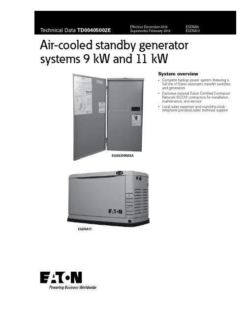
1Air-cooled standby generator systems 9 kW and 11 kWSystem overview• Complete backup power system featuring afull line of Eaton automatic transfer switchesand generators• Exclusive national Eaton Certified ContractorNetwork (ECCN) contractors for installation,maintenance, and service• Local sales expertise and round-the-clocktelephone pre-/post-sales technical supportEGSX200NSEAEGENA11T able 1. Generator featuresFeatures BenefitsEngine• Overhead valve industrial enginedesign (OHVI)• ”Spiny-lok” cast iron cylinder walls• Electronic ignition/spark advance• Full pressure lubrication system• Low oil pressure shutdown system• High temperature shutdown • Maximizes engine “breathing” for increased fuel efficiency. Plateau-honed cylinder walls and plasma moly rings help engine run cooler, reducing oil consumption. Because heat is the primary cause of engine wear, the OHVI has a significantly longer life than competitive engines • Rigid construction and added durability provide long engine life• Assured smooth, quick start every time• Pressurized lubrication to all vital bearings means better performance, less maintenance, and significantly longer engine life. Now featuring a 2-year/200-hour oil change interval• Superior shutdown protection prevents catastrophic engine damage from low oil• Prevents damage due to overheatingGenerator• Revolving field• Skewed stator (only)• Displaced phase excitation• Automatic voltage regulation• UL T 2200 Listed • Allows for smaller, lightweight unit that operates 25% more efficiently than a revolving armature generator• Produces a smooth output waveform for electronic equipment compatibility• Maximizes motor starting capability• Regulates the output voltage to ±2%, which prevents damaging voltage spikes• Compliant with all safety regulationsNew controller and controls• Auto/Manual/Off illuminated buttons• Utility voltage sensing• Utility interrupt delay• Engine warm up• Engine cool down• Main line circuit breaker• Electronic governor• Smart battery charger• Two-Line LCD multilingual display• Sealed, raised buttons• Generator voltage sensing• Programmable exercise • Selects the operating mode for easy, at-a-glance status indication in any condition• Weather-resistant interface allows smooth programming and operations for the user• Constantly monitors utility voltage, set points 60% dropout, and 80% pickup of standard voltage • Ensures engine is ready to assume the load, set point approximately 5 seconds• Allows engine to cool prior to shutdown, set point approximately 1 minute• Protects generator from overload• Maintains constant 60 Hz frequency• Delivers charge to the battery only when needed at varying rates depending on outdoor air temperature. Compatible with lead acid and AGM-style batteries• Provides homeowners easily visible logs of history, maintenance, and events up to 50 occurrences • Smooth, weather-resistant user interface for programming and operations• Constantly monitors generator voltage to ensure the cleanest power delivered to the home• Operates engine to prevent oil seal drying and damage between power outages by running the generator for 12 minutes every other week. Also offers a selectable setting for weekly or monthly operation providing flexibility and potentially lower fuel costs to the ownerUnit• SAE weather-protective enclosure• Enclosed critical grade muffler• Small, compact, attractive • Sound attenuated enclosures ensure quiet operation and protection against Mother Nature, withstanding winds up to 150 mph. Hinged key locking roof panel for security. Lift-out front for easy access to all routine maintenance items. Electrostatically applied textured epoxy paint for added durability• Quiet, critical grade muffler is mounted inside the unit to prevent injuries. Complies with local dB noise levels• Makes for an easy, eye-appealing installationInstallation system• 1-foot flexible fuel line connector• Direct-to-dirt composite mounting pad• Integral sediment trap • Easy installation• Complex lattice design prevents settling or sinking of the generator system• Prevents particles and moisture from entering the fuel regulator and engine, prolonging engine lifeWarranty a• 5-year limited warranty:• Years 1 and 2—limited comprehensive coverage on mileage, labor, and parts (warranty certification required)• Year 3—limited comprehensive coverage on parts only• Years 4 and 5—limited comprehensive coverage on engine (short block) and alternator (rotor and stator) parts only a For warranty details, refer to the “Eaton Air-Cooled Automatic Standby Generators” warranty statement.T able 2. Compatible automatic transfer switches aFeatures BenefitsEGSU series featuringuniversal active loadmanagement• Truly active load management system• RTC-100 controller with built-in intelligence• Universal compatibility with any generator brand (single-phase, 240 V)• No programming necessary• Whole house surge included (catalog number: CHSPT2ULTRA)• 50 or 60 Hz• Current sensors (CTs) included• Built-in 7-, 14-, and 28-day plant exerciser• Load and no-load transfer• Meets NEC T Article 702.5 for optional standby backup power systems• UL 1008 Listed• Actively balances electrical loads in the household, adjusting tohomeowner’s lifestyle• Complete home surge protector included to protect home electronicsand appliances against surge events• Complete power monitoring for greater accuracy and load management:voltage, current, and frequency• Power monitoring system allows 100% use of power output ratingin the generator• Contractor-friendly installation, requires fewer connections tothe generator• Environmentally friendly: allows downsizing of generator resultingin decrease of greenhouse gas (GHG) emissions, and reduces gasconsumption by 15% or moreEGSX series featuringload shedding• Two sets of contacts for load shedding• Simplified, non-redundant relay-interface system• Terminal block termination; connections labeled to match generatorconnections• Three-point keyhole mounting system for quick, level installation• Optimal wire bending space• Commercial grade main breaker included• UL 1008 compliant• Meets NEC Article 702.5 for optional standby backup power systems• Easy, intuitive installation for labor savings• Compatible with Eaton generators and most standby generator brands• Smallest footprint in the industry (400 A model)Warranty b• 1-year limited warranty from the date of installation or 18 months from the date of shipment, whichever occurs first• Extended and special warranties available:• 24 months—2% of contract price• 30 months—3% of contract price• 36 months—4% of contract pricea For selection information, visit our online green ATS interactive demo at .b For warranty details, refer to Eaton Selling Policy 25-000.T able 3. Automatic transfer switch specificationsAmperes VoltagesNumberof polesServiceentranceNumberof circuitsincluded a FrequencyEnclosuretypeContactorwire sizeranges(s)Numberof cablesper phaseWithstandcurrent(rms) at240 VacMost commongeneratorsizes bCatalognumberEGSU series50120/2402—2450/60NEMA 3R#14–#2/0110,0009, 11, 16 kW EGSU100L24RACA 50120/2402——50/60NEMA 3R#14–#2/0110,0009, 11, 16 kW EGSU100ACA 100120/2402Y—50/60NEMA 3R#14–#2/0110,0009, 11, 16 kW ESGU100NSEACA 100120/2402Y—50/60NEMA 3R#4–300 kcmil125,0009, 11, 16 kW EGSU150NSEACA 200120/2402——50/60NEMA 3R#4–300 kcmil125,00016, 20, 22 kW EGSU200ACA 200120/2402Y—50/60NEMA 3R#4–300 kcmil125,00016, 20, 22 kW EGSU200NSEACA 200120/2402Y—50/60NEMA 3R750 kcmil–2 /300 kcmil–1/01/235,000>22 kW EGSU400NSEACA EGSX series50120/2402Y1250/60NEMA 1#14–#6150009, 11 kW EGSX50L12 50120/2402—1250/60NEMA 3R#14–#6150009, 11 kW EGSX50L12R 100120/2402——50/60NEMA 3R#14–#2/0110,0009, 11, 16 kW EGSX100A 100120/2402Y—50/60NEMA 3R#14–#2/0110,0009, 11, 16 kW EGSX100NSEA 100120/2402—2450/60NEMA 3R#14–#2/0125,0009, 11, 16 kW EGSX100L24RA 150120/2402Y—50/60NEMA 3R#4–300 kcmil125,00016, 20, 22 kW EGSX150NSEA 200120/2402——50/60NEMA 3R#4–300 kcmil125,00016, 20, 22 kW EGSX200A 200120/2402Y—50/60NEMA 3R#4–300 kcmil125,00016, 20, 22 kW EGSX200NSEA 400120/2402Y—50/60NEMA 3R750 kcmil–2 /300 kcmil–1/01/235,000>22 kW EGSX400NSEAa Uses CH type circuit breakers.b For reference only. Generator size must be determined by actual load calculations.T able 4. Generator specificationsCatalog numberEGENA9EGENA11 GeneratorRated maximum continuous power capacity (LP)/(NG)9000/8000 watts a11,000/10,000 watts a Enclosure Aluminum AluminumRated voltage240240Rated maximum continuous load current 240 V b37.5/33.3 NG45.8/41.7 NGTotal harmonic distortion Less than 5%Less than 5%Main line circuit breaker40 A50 APhase Single SingleNumber of rotor poles22Rated AC frequency60 Hz60 HzPower factor 1.0 1.0Battery requirement (not included)Group 26R, 12 V and525 cold-cranking amperes minimumor Group 35AGM 650 cold-crankingamperes minimum Group 26R, 12 V and525 cold-cranking amperes minimum or Group 35AGM 650 cold-cranking amperes minimumUnit weight lb (kg)340/154348 (158)Dimensions in inches (mm) L x W x H 48.00 x 25.00 x 29.00(1219.2 x 635.0 x 736.6)48.00 x 25.00 x 29.00(1219.2 x 635.0 x 736.6)Sound output in dBA at 23 ft with generatoroperating at normal load6663EngineType of engine OHVI OHVI V-TWINNumber of cylinders12Displacement410 cc530 ccCylinder block Aluminum with cast iron sleeve Aluminum with cast iron sleeve Valve arrangement Overhead valve Overhead valveIgnition system Solid-state with magneto Solid-state with magneto Governor system Electronic Electronic Compression ratio9.0:19.5:1Starter12 Vdc12 VdcOil capacity including filter Approximately 1.1 qt/1.0 L Approximately 1.7 qt/1.6 L Operating RPM3,6003,600Fuel consumption cNatural gas ft³/hr (m³/hr): 1/2 loadFull load 90 (2.55)120 (3.4)107 (3.03)159 (4.50)Liquid propane ft³/hr (gal/hr) (liters/hr): 1/2 loadFull load 31.6 (0.87) (3.29)50 (1.37) (5.2)44.4 (1.22) (4.62)71.6 (1.97) (7.45)a Suitable for “optional” standby backup power only, as indicated by NEC Article 702. Not suitable for legally required “emergency” life safety applications as required by NEC Article 700 and NFPA 110/99. All ratings in accordance with BS5514, ISO3046, and DIN6271. Maximum wattage and current are subject to and limited by such factors as fuel BTU content, ambient temperature, altitude, engine power, and condition. Maximum power decreases about 3.5% for each 1000 feet above sea level, and also will decrease about 1% for each 12 °C (10 °F) above 15.5 °C (60 °F).b LP = Liquid propaneNG = Natural gasc Gas pipe sizing is critical for the proper operation of the generator. Fuel pipe must be sized for full load. Required fuel pressure to generator fuel inlet at all load ranges—3.5 to 7 inches water column(7 to 13 mm mercury) for natural gas, 10 to 12 inches water column (19 to 22 mm mercury) for LP gas. For BTU content, multiply ft3/hr x 2500 (LP) or ft3/hr x 1000 (NG). For Megajoule content,multiply m3/hr x 93.15 (LP) or m3/hr x 37.26 (NG).T able 5. Generator controlsFeatures DescriptionTwo-line plain text multilingual LCD display Simple user interface for ease of operationMode buttonsAutoManualOffAutomatic start on utility failure. 7-day exerciser (7-, 14-, and 28-day exerciser when coupled with EGSU ATS)Start with starter control, unit stays on. If utility fails, transfer to load takes placeStops unit. Power is removed. Control and charger still operateReady to run/maintenance messages StandardEngine run hours indication StandardProgrammable start delay between 2 and 1500 seconds Standard (programmable by dealer only)Utility voltage loss/return to utility adjustable From 140 V to 171 V/190 V to 216 VFuture set capable exerciser/exercise set error warning StandardRun/alarm/maintenance logs50 events eachEngine start sequence Cyclic cranking 16 seconds on, 7 rest (90 seconds maximum duration)Starter lockout Starter cannot re-engage unit 5 seconds after engine has stoppedSmart battery charger StandardCharger fault/missing AC warning StandardLow battery/battery problem protection and battery condition indication StandardAutomatic voltage regulation with overvoltage and undervoltage protection StandardUnderfrequency/overload/stepper overcurrent protection StandardSafety fused/fuse problem protection StandardAutomatic low oil pressure/high oil temperature shutdown StandardOvercrank/overspeed at 72 Hz/RPM sense loss shutdown StandardHigh engine temperature shutdown StandardInternal fault/incorrect wiring protection StandardCommon external fault capacity StandardField-upgradable firmware StandardT able 6. Compatible accessories and replacement parts—EGENA generatorsDescription Benefits/features Catalog number Maintenance and general accessoriesBattery pad warmer The pad warmer rests under the battery. Recommended for use if the temperature regularly falls below 0 7F.(Not necessary for use with AGM-style batteries).7101CHOil warmer Oil warmer slips directly over the oil filter. Recommended for use if the temperature regularly falls below 0 7F.7102CH Breather warmer The breather warmer is for use in extreme cold weather applications. For use with standard controllersonly in climates where heavy icing occurs.7103CHMaintenance kit for 9 kW generators Includes all hardware and material necessary to perform scheduled preventive maintenance. Compatiblewith model EGENX9 only.6482CHMaintenance kit for 11 kW generators Includes all hardware and material necessary to perform scheduled preventive maintenance. Compatiblewith model EGENX11 only.6483CH Bisque color paint kit Ideal for touch-up paint/maintenance to generator enclosure against scratches and future corrosion.EGENPAINT Generator fascia Enhances aesthetics. Installs in seconds (standard with EGENX20A and EGENX22A models).EGENFASCIA Air-cooled transportation cart User-friendly assembly, attaches to lifting holes. Smart design allows only one person to lift the unitoff of wooden pallet and position it for final installation.EGENCART MonitoringMobile wireless remote monitor Most advanced generator status monitoring system. Allows connectivity and settings programmingvia smart devices (laptops, smartphone, pad, etc.). Sends automated emails and/or text messagesto multiple users. Requires cell phone signal and subscription.EGENMOBILEIn-house wireless monitor In-house generator status basic monitoring system. No computer connectivity required. 600 ft radiusof wireless coverage.EGENINHOME T able 7. Replacement parts—EGSX ATSComponent Catalog number50 A100 A150 A200 A400 AContactor99-5643-899-5638-1299-5702-1599-5702-1599-5702-16 Wire harness a99-5643-799-5638-1399-5702-1799-5702-1799-5702-18 Neutral bar99-5643-699-5638-799-5702-699-5702-699-5702-13 Ground lugs99-5643-499-5638-599-5702-499-5702-499-5702-4 Service entrance breaker—99-5638-4CSR2150CSR2200KD2400 Contactor lugs99-5643-599-5638-699-5702-599-5702-599-5702-12 a Includes relay and mounting base.T able 8. Replacement parts—EGSU ATSComponent Catalog number100 A150 A200 A400 AController RTC100RTC100RTC100RTC100 Contactor99-5638-1299-5702-1599-5702-1599-5702-16 Wire harness99-5638-1499-5702-799-5702-799-5702-19 Service entrance breaker99-5638-4CSR2150CSR2200KD2400 c Ground bar99-5638-5 a99-5702-49-5702-499-5702-4 Contactor lugs99-5638-699-5702-599-5702-599-5702-12 Neutral bar99-5638-7 b99-5702-699-5702-699-5702-13 Current sensors CS200CS200CS200CS400 Whole house surge protector CHSPT2ULTRA CHSPT2ULTRA CHSPT2ULTRA CHSPT2ULTRAa For EGSU100L24RACA, order ground bar catalog number 99-5638-15.b For EGSU100L24RACA, order neutral bar catalog number 99-5638-17.c For breaker lugs, order catalog number 2TA401K.Figure 1. Air-cooled generator 9 kW and 11 kW—dimensions in inches (mm) Dimensions shown are approximate. Design and specificationssubject to change without notice. For additional information, visitour website at , call our technicalresource center at (877) ETN-CARE (386-2273), or contact yourlocal Eaton authorized distributor.Eaton1000 Eaton Boulevard Cleveland, OH 44122 United States © 2016 EatonAll Rights ReservedPrinted in USAPublication No. TD00405002E / Z19034 December 2016Eaton is a registered trademark.All other trademarks are propertyof their respective owners.Air-cooled standby generator systems 9 kW and 11 kWTechnical Data TD00405002EEffective December 2016Figure 2. Plan view of an EGSX150NSEA/EGSX200NSEA—dimensions in inches (mm)T able 9. Automatic transfer switches approximate dimensions in inches (mm)Amperes Width Height Depth Weight in lb (kg) 5014.25 (362.0)21.00 (533.4) 4.00 (101.6)23 (10.43) 10014.46 (367.3)16.87 (428.5) 5.32 (135.1)25 (11.33)100 with loadcenter14.46 (367.3)29.33 (745.0) 5.32 (135.1)38 (17.23) 15014.46 (367.3)29.33 (745.0) 5.32 (135.1)45 (20.41)200 a14.46 (367.3)29.33 (745.0) 5.32 (135.1)45 (20.41) 40023.14 (587.8)37.56 (954.0)10.00 (254.0)130 (58.96)a Height for 200 A non-SE is 25.08 (637.0).。
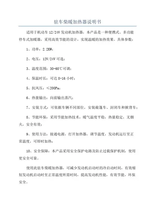
驻车柴暖加热器说明书
适用于机动车12/24V发动机加热器,本产品是一种便携式、多功能
停车式加暖器,采用高效节能的设计,实现温暖的加热效果。
具体参数:
1、功率:2.2KW;
2、电压:12V/24V可选;
3、温度范围:30-60℃可调;
4、保温时长:可达8-16小时;
5、抗风压:≤200Pa;
6、热量输出:向前输出蒸汽;
7、安装方式:可依据车辆不同部位,安装敞篷车、封闭车和掀背车;
8、节能环保:采用节能加热技术,暖气温度平稳,热量稳定,无烟火,安全有效;
9、使用方法:接通电源,打开加热器,调节温度,发动机运行至正
常温度,可即时加热;
10、安全保障:本产品采用安全保护电路及防止过载保护机制,使用
更安全可靠。
使用此驻车柴暖加热器,可减少发动机启动时的冷启动时间,有效缩
短发动机启动时至正常温度所需时间,提高发动机性能,有效节能,环保
安全。
库克斯曼驻车加热器CS5-H/Q1、C1使用说明书目录1.遥控器功能及按键使用说明···········································2.显示屏显示说明··························································2.设定加热器工作时间方法··············································3.启动加热器 ··························································· - 5 -4.中止加热器工作··························································安装库克斯曼驻车加热器的理由:●寒冷的冬季,让您在上车前就能迅速预热发动机乘务仓,驱走严寒、自动除霜,改善驾乘环境,从此不需再用暖库;●预热发动机,大大减少低温启动带来的冷磨损。
驻车采暖使用说明书第一部分:产品概述驻车采暖器是一种专为汽车驾驶舱设计的取暖设备。
它能够提供舒适的驾驶环境,同时也保障了驾驶者的安全。
驻车采暖器运行于车辆的电力系统,通过热风和辅助电源为车辆提供暖气。
它是冬季驾驶的理想选择,适用于各种类型的车辆。
本说明书将为您详细介绍驻车采暖器的使用方法、注意事项和常见问题解答。
第二部分:使用方法1.准备工作:在使用驻车采暖器之前,请确保您已经熟悉驾驶舱的布局,并能够方便地操作控制面板。
另外,请确保车辆的电力系统正常运行,以免影响驻车采暖器的使用。
2.打开电源:将车辆的电源开启,并将发动机保持在怠速状态。
3.打开驻车采暖器:找到驻车采暖器的控制面板,按下打开按钮。
在启动时,请注意不要将面板暴露在阳光、雨水或其他液体中,以免损坏电气元器件。
4.调整温度和风速:在控制面板上选择合适的温度和风速。
温度通常有高、中、低三档可供选择,风速也有相应的高、中、低三档。
5.等待预热:一般情况下,驻车采暖器需要一定时间进行预热,使得热风能够快速达到所设定的温度。
请耐心等待,不要过度调高温度或风速,以免造成过热或其他安全隐患。
6.使用结束:在使用完驻车采暖器后,请及时关闭电源,避免不必要的能源浪费和安全隐患。
第三部分:注意事项1.安全第一:在使用驻车采暖器时,请务必确保车辆停在开阔、通风良好的地方。
切勿在密闭的车库或其他封闭空间中使用,以免产生一氧化碳等危险气体。
2.避免长时间使用:驻车采暖器的建议使用时间为30分钟至1小时。
请不要将其超过建议时限,以免对电瓶和车辆的电力系统造成负担。
3.防止过热:在使用驻车采暖器时,请不要将温度调得过高,以免对车辆的电气元器件和驾驶员的安全造成威胁。
4.定期维护:请按照产品说明进行定期维护,清洁和更换滤网等零部件,以确保驻车采暖器的正常运行。
5.防止摔落和碰撞:请确保驻车采暖器及其控制面板固定牢固,避免在行驶中发生碰撞或摔落情况。
第四部分:常见问题解答1.为什么我的驻车采暖器没有热风吹出来?答:可能是由于以下原因导致:a.检查是否设置了正确的温度和风速。
驻车加热器使用注意事项摘要:I.引言- 驻车加热器的定义与作用- 文章主题及目的II.驻车加热器的安装- 安装位置及注意事项- 安装过程中的风险及预防措施III.驻车加热器的使用- 操作步骤及注意事项- 驻车加热器使用中可能出现的故障及解决方法IV.驻车加热器的维护与保养- 日常维护措施- 定期检查与保养V.结论- 总结驻车加热器的使用注意事项- 强调维护与保养的重要性正文:驻车加热器使用注意事项随着气温的逐渐降低,驻车加热器成为了许多车主在冬季必备的设备。
驻车加热器能够在车辆停止时,为车内提供温暖的环境,大大提高了驾驶舒适度。
然而,正确使用和维护驻车加热器尤为重要,不仅能够延长设备的使用寿命,还能确保车内人员的安全。
本文将详细介绍驻车加热器的使用注意事项。
一、驻车加热器的安装1.安装位置驻车加热器应安装在车辆外部,避免影响车内空间。
同时,应选择通风良好且避免阳光直射的位置。
2.注意事项在安装过程中,应注意避免设备与车辆其他部件产生干涉,防止设备受损。
此外,还需确保电线敷设安全,避免因潮湿、磨损等原因导致短路。
二、驻车加热器的使用1.操作步骤使用驻车加热器前,先打开车辆电源,然后按下驻车加热器上的开关。
根据需要,可调整加热器的温度及工作时间。
2.注意事项使用驻车加热器时,应注意观察设备工作状态,确保正常运行。
同时,避免长时间使用高温档,防止设备过热。
另外,使用过程中请勿离开车辆,防止发生意外。
三、驻车加热器的维护与保养1.日常维护措施每天使用驻车加热器后,应清理设备表面的灰尘及污物,确保清洁。
同时,检查设备连接部位是否牢固,如有松动,应及时拧紧。
2.定期检查与保养每隔一段时间,应对驻车加热器进行详细检查。
检查包括:电源线是否完好,设备内部是否有异响、异味等异常情况。
若发现异常,应立即停止使用,联系专业人员进行维修。
总之,驻车加热器为车主在冬季提供了舒适的驾驶环境,但正确使用及维护驻车加热器同样重要。
电加热器安全操作及保养规程1. 前言电加热器作为一种常用的供暖设备,在冬季被广泛使用。
但是,如果使用不当或者保养不当,电加热器极易造成火灾、电击等安全问题。
为了避免这些问题的发生,本文将介绍电加热器的安全操作及保养规程。
2. 安全操作规程2.1. 选购安全型电加热器购买电加热器时,一定要选择符合国家安全标准的产品。
应当选择产品带有CCC标志的产品,或者具备UL、CE认证等国际认证标志的产品。
2.2. 安装位置与使用环境电加热器应该放置在室内干燥通风,无易燃物品、可充电物品和易燃气体等危险物品的区域。
使用时必须保持室内适当的空气流通,不得将电加热器放置在堆放杂物和窗帘、床垫等易燃物品附近。
2.3. 用电安全使用电加热器时,应注意以下事项:•检查供电电压是否符合电加热器的额定电压;•使用合格的插座进行插拔,避免使用带划痕或变形的插座;•电加热器的接地线必须接地可靠;•不得在电加热器上堆放物品或悬挂物品。
2.4. 选择合适的加热器功率电加热器的功率应该根据房间的大小来选择,一般每平方米的房间面积应选用100W左右的电加热器。
过低的功率不足以供暖,过高的功率则会造成过载和热量浪费。
2.5. 使用过程中的注意事项•不得用湿手触碰电加热器;•不得将其它物品放在电加热器上;•不得将电加热器煮水、烤面包等其它用途;•不得随意移动电加热器。
2.6. 使用后的操作•使用后应如实拔掉电源插头;•在使用中发现电加热器故障时,应立即停止使用并及时联系维修人员;•在长时间停用后重新使用时,应拆开电加热器清理除尘。
3. 保养规程为了延长电加热器的使用寿命并保证使用安全,需要进行定期保养。
3.1. 定期清洁每个供暖季节结束后,需要对电加热器进行清洁,清除其上的尘土及杂物。
首先将电源插头拔出,然后使用干净的软布擦拭,最后用真空吸尘器将其内部与表面的灰尘吸尽。
3.2. 使用防尘罩在长时间不使用电加热器时,应使用专门的防尘罩进行保护。
道路加热设备的操作和维护管理手册编制一、前言道路加热设备是为了保证道路在冬季能够顺畅通行而设计的一种设备。
本手册旨在提供道路加热设备使用人员的操作指南和维护管理要求,以确保设备能够安全高效地运行。
二、设备介绍1. 设备概述道路加热设备是通过加热元件将道路表面的冰雪熔化,达到清除冰雪、防止结冰的目的。
主要由加热元件、供电系统、控制系统等组成。
2. 设备结构(此处应描述设备的结构、主要组成部分和工作原理,注意不要涉及政治)三、操作指南1. 设备开机前准备a. 确保设备周围环境干燥清洁,无杂物阻挡。
b. 检查供电系统的接地连接是否良好。
c. 检查加热元件的完好性,是否存在损坏。
2. 设备开机操作a. 打开供电开关,确保设备供电正常。
b. 打开控制系统,根据实际情况调整加热元件的温度和工作时间。
3. 设备运行时操作a. 监测设备工作状态,确保设备正常运行,加热元件温度不超过设定值。
b. 定期巡检加热元件,检查是否存在损坏或老化,如有问题需及时更换或修复。
4. 设备停机操作a. 关闭控制系统,确保加热元件停止工作。
b. 关闭供电开关,切断设备供电。
四、维护管理要求1. 设备定期检查a. 定期对加热元件进行检查,如发现松动、损坏等情况,需及时修复或更换。
b. 定期检查供电系统和控制系统,确保其正常运行。
2. 设备定期清洁a. 定期对设备进行清洗,清除附着在设备上的污物和尘土。
b. 清洁时注意不要使用过于湿润的物品,以免影响设备的正常运行。
3. 设备冬季空闲期的保养a. 在冬季道路不需要加热的时候,需对设备进行保养,包括清洁、紧固螺丝、润滑等工作。
b. 如设备需要长时间停机,应采取防潮防腐等措施,以延长设备的使用寿命。
4. 设备故障处理a. 如遇到设备故障,应及时与专业维修人员联系,切勿私自拆卸或修理设备,以免造成更大的损坏。
b. 维修人员应及时到达现场,对故障设备进行检修或更换。
五、安全注意事项1. 操作人员需严格按照操作指南操作设备,切勿擅自调整设备参数或进行无关操作。
C12LR-ZJN-9AQ12LR-ZJN-9B/C/D智能节油暖车器使用维护说明书朝阳朗瑞车辆技术有限公司售后服务电话:400-106-0005前言感谢您使用朝阳朗瑞智能节油暖车器朝阳朗瑞智能节油暖车器是柴油机的一个附加装置,具有独立的加热功能。
暖车器以车载电瓶为热源动力,通过燃烧车辆自身的燃油产生热量。
暖车器的循环系统与发动机的冷却系统连接在一起,在发动机不工作时,暖车器自带的水泵将产生的热量传递给发动机,进行预热,从而提高发动机机体的启动温度,解决发动机在低温下启动困难,磨损严重的历史性难题,缩短发动机怠速升温的环节,节约燃油消耗,还可以提高驾驶室内的温度,给驾驶员一个温暖舒适的驾驶空间,在冰雪的世界里自由驰骋。
暖车器采用单片机进行全自动控制,产品体积小,重量轻,结构紧凑,安装方便,维护保养简单,安全可靠。
本手册内容有可能改动,恕不另行通知,但本手册内容与所购产品一致。
公司保留对说明书中描述产品进行修改而不事先通知的权利,最终功能以实际产品为准,本公司具有最终解释权。
如果在使用中出现故障,请与我公司销售部或指定的服务网点联系。
本公司竭诚为您服务。
目录警示页 (1)1暖车器的安装 (2)2暖车器电磁泵的安装 (3)3暖车器安装后的调试 (3)4暖车器主要技术参数 (4)5暖车器的功能及操作步骤 (4)6 线束连接示意图 (5)7 故障显示功能 (5)8常见故障分析与排除 (6)9 常规维护保养 (7)10 遥控器连接及使用 (8)警示页危险!在任何加热过程中,都要在关闭暖车器控制开关3分钟后,才能关闭暖车器电源开关,否则会有激热爆炸隐患!警告!在暖车器安装后,首次进行加热前必须将放气螺栓放松,将管路中的气体排出,然后再进行加热!※暖车器严禁无水干烧 !※暖车器裸漏导线严禁拉扯,碾压 !注意!1、暖车器总成的安装必须平稳、牢固,避免暖车器在随车使用过程中出现松动现象。
2、暖车器进出水管在安装过程中要保证一一对应关系。
3、线束的正极连接车载电瓶正极,负极连接在电源开关后面,关闭电源开关后,使整车及暖车器断电。
4、油箱吸油杆,安装时可根据油箱高度不同,现场截取吸杆的长度,再套上柴油滤网,连接即可。
5、要严格按照使用维护说明书要求进行常规维护保养。
本产品保质期为两年。
6、安装排气管时远离塑料件与导线。
7、安装输油管时注意管路密封。
1暖车器的安装暖车器进出水管在安装过程中要保证一一对应关系。
暖车器水流方向低进高出,水泵应安装在底盘最低处。
加热器通过加热器支架固定在车上,先将加热器支架用螺栓固定好,再将加热器放在支架的托槽内,出水口方向对准发动机的位置,两边分别用M6*10的螺栓紧固即可,固定加热器支架的四脚时最好用橡胶垫缓冲。
安装小窍门:加热器总成安装完成后,把管路最高端的接口拔掉,便于加入冷却液时的气体排出,等待最高端流出冷却液时,再把最高端的接口安装好即可。
1.2排气管的安装进气口是燃油在燃烧室内燃烧提供助燃空气的重要通道,为保证燃油充分燃烧应保证燃烧空气吸入充足和新鲜,保持进风口的畅通,不能被杂物堵住。
排气管安装时两端分别用卡箍固定,消音器用支架固定。
注意:加热器工作时,排气管的温度很高,安装时要远离车体的导线、塑料件以免损坏。
安装时排气口的方向不能迎向气流,也不能被杂物或雨雪堵住,以免影响尾气的排放。
1.3油箱吸杆的安装:①在柴油油箱上面打一个¢25mm的孔(汽油油箱要卸下油箱内的汽油泵,在固定盘面合适位置打一个¢18mm的孔),去除毛刺;把油箱吸杆按油箱的高度截取适当长度(吸油管底部与油箱底部保持20~30mm距离),装入吸杆,依次装入密封圈、压片、调好出油方向,最后用螺母锁紧。
②连接输油管时,各接头注意密封,防止漏气使燃油供应不上。
③要注意检查油箱的通气孔。
④燃油管应远离发热源,以免损坏管路。
2暖车器电磁泵的安装暖车器油路的安装最好是一路向上倾斜,方便排出油路中的气体。
要注意检查油箱的通气孔,避免油箱产生负压。
输油管应远离有热源的位置,安装时不能靠近消音器、排气管等,并用波纹管保护,在适宜的地方进行捆扎,捆扎间距不大于50cm。
电磁泵安装示意图:输油管3与电磁泵2、油箱吸杆4、暖车器5、柴油滤网7的各部件连接处用橡胶燃油管6连接,对接处应严密无缝隙。
电磁泵安装方向示意图:输油泵出油方向应与泵体上的箭头方向一致,输油泵用抱箍固定在合适位置。
3暖车器安装后的调试暖车器安装完毕后必须先打开管路中串联的水阀开关,把放气螺栓放松,等管路中气体全部排出后将放气螺栓紧固,紧固后不得有漏水现象,使水泵内充满防冻液,再打开水泵开关,将整个管路充满防冻液。
暖车器开始加热前先检查安装状况,各管路连接处不得有漏水现象;所有螺栓紧固,不得松动;各电连接器一一对应,电连接器及电缆线固定牢固。
暖车器安装完毕后,可以启动发动机,让发动机的水泵将水充满整个暖车器的管路中。
适当加大油门便于将安装时管路中产生的气体排出。
暖车器尽可能的安装在发动机机仓内,越靠近发动机越有利于热交换,越有利于暖车器水管内气体的排出。
注意查看水箱内液面高度,适量加注防冻液,以免水箱内缺水,暖车器不能正常工作。
暖车器在车辆上安装结束后,在加热和不加热时均不能在加热器主机上放置或覆盖任何物品。
※严禁在暖车器无水时启动加热功能。
4暖车器主要技术参数5暖车器功能及操作步骤液体暖车器采用全自动闭环控制,使用者仅通过暖车器电源开关和暖车器运行开关就可以对暖车器进行整个加热过程的操作。
首先,在起动暖车器加热前,检查暖车器各管路(包括水管、油管)是否有泄漏现象。
在驾驶员终端,有暖车器控制开关。
开关打开到中间档位时指示灯常亮,水泵单独工作,此时不处于加热状态。
开至此档位有助于初次安装时水管里存留气体的排出。
开关打开至加热档位,暖车器开始检测自身器件,器件正常后,点火塞开始预热,预热80秒开始点火,控制器探测到暖车器内火焰稳定燃烧时、点火成功,开始正常燃烧。
若第一次点火失败,自动进入第二次预热点火过程。
如果三次点火均失败,控制器进入自我保护,请检查油管是否正确连接。
暖车器正常燃烧后会持续对防冻液进行加热,暖车器出口水温到达70℃,暖车器自动降低功率慢速加热(汽油产品无慢速加热功能)。
当水温达到78℃时,暖车器停止供油燃烧,进入保温状态,开关板指示灯慢速闪烁,风扇电机吹风冷却3分钟后停止工作,水泵此时仍在旋转,当水温下降到60℃时,暖车器自动启动,开始加热。
若用户不需要保温功能,关闭开关板即可,暖车器退出保温状态,结束加热工作。
在加热期间禁止关闭整车电源开关(加热过程中突然关闭风机和水泵,暖车器中的高温燃气就会停留甚至反方向流动,这样会烧毁控制及其他部件)。
关闭加热开关,等3分钟风机、水泵停止运行后,方可切断电源。
6 线束连接示意图加热器水泵信号 红色 5工作指示灯 黄色 4电源正极 红色 2开关信号 蓝色 1电源负极 黑色 312V 暖车器保险盒所用标准保险为:30A7 故障显示功能故障代码通过开关板上绿色指示灯交替闪烁显示出来。
快闪短脉冲:0.2秒短脉冲间隔0.2秒8常见故障分析与排除9 常规维护保养暖车器冬季使用过后,应从车上取下进行清洗和检修,添加润滑脂。
通常在一个取暖季节内不用大修,如发现热效率明显下降,不易点火或发生其他故障应及时查找原因排除。
8.1、暖车器运转一段时间后,应拧下电热塞、取出挥发网清理积碳,如发热丝烧断,应拆下更换新的电热塞。
8.2、如积碳过多,引起热效率降低时,应清理水套体内壁散热片及燃烧室内的积碳。
8.3、油箱、油管及滤油装置应保持清洁和畅通,根据实际情况定期清洗。
8.4、暖车器循环系统中应使用与环境温度相适应的防冻液或防冻液混合物作冷却液介质。
8.5、暖车器强制循环泵,根据使用情况,定期检查,如发现密封面漏水或起动时运转困难等故障,应及时检修。
8.6、暖车器的自动控制器、电磁阀及其他电器元件均按一般低压电器维护办法进行维护,自动控制器各性能参数均经厂家认真调整,用户不得擅自改动。
8.7、暖车器所使用的电机,正常情况下,使用1000小时不需维修,如因使用时间过长或其他原因造成工作不正常时,应予以检修,检查碳刷磨损或轴承润滑情况,必要时添加润滑脂或更换预磨合碳刷。
8.8、在不用暖车器的季节内,应将暖车器电源断开,保持暖车器清洁、干燥,严禁将加热器侵入水中,严禁淋雨,严禁长时间在阳光下直晒。
10遥控器连接及使用遥控器由手持命令发射端、接收执行端和天线3部分组成,无线遥控距离,空旷地大于800米。
12V、24V电压通用,遥控器手持命令发射端和接收执行端配套使用,一一对应关系,混用无效。
遥控器与开关板可以互换使用,在使用开关板的车辆上安装遥控器,拔掉开关板与线束的对接插头,将遥控器接收执行端的对接头与线束连接,另外将执行端黑色负极线OT4-6的铜接头与搭铁线相连接,再将天线与接收执行端正确连接后,把多余天线困扎好,磁铁天线吸附在适当位置。
遥控器对接插头 OT4-6搭铁线接收执行端有3个指示灯,分别为蓝色水泵灯,单独开水泵时亮;黄色状态指示灯,相当于开关板上的指示灯,用于读取暖车器的工作状态和故障类型判断;红色加热指示灯,加热时灯亮。
接收执行端上的三个按键功能和遥控功能可以并行使用,由遥控器远程启动加热功能,执功能,也可以用遥控器远程关闭。
注意:手持执行端初次安装在车辆上使用时,由于安装过程中导线的连接存在抖动现象,如果安装结束后不能用遥控器启动,需要拔掉遥控器对接插头,等待1分钟,电压完全释放后,再次连接,即可正常启动。
遥控器手持命令发射端需要两节1.5V AAA 电池供电。
安装时注意电池正负极,不要装错。
用遥控器起动或者停止加热时,如果执行端收到该指令,会立即返回接收信号,手持命令发射端上的指示灯会亮2秒,确认信号以发射并成功接收。
如果按完加热或停止按键,指示灯没有点亮,可能遥控器超过有效天线与遥控器命令执行端连接处遥控器使用距离受环境影响较大,请确认每次遥控成功后,再离开,以免影响您的行程。