YTC定位器YT-1000R (C)调节
- 格式:doc
- 大小:1.68 MB
- 文档页数:11
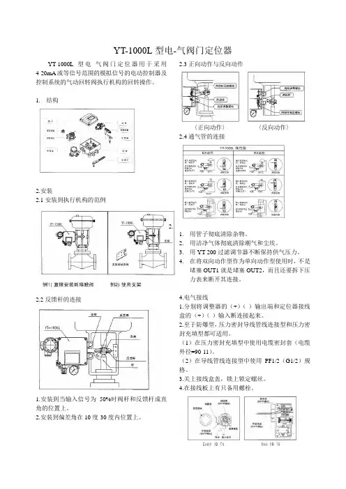
YT-1000L型电-气阀门定位器YT-1000L型电-气阀门定位器用于采用4-20mA或等信号范围的模拟信号的电动控制器及控制系统的气动回转阀执行机构的回转操作。
1.结构2.安装2.1安装到执行机构的范例2.2反馈杆的连接1.安装到当输入信号为50%时阀杆和反馈杆成直角的位置上。
2.安装到偏差角在10度-30度内位置上。
2.3正向动作与反向动作〈正向动作〉〈反向动作〉2.4通气管的连接2.1.用管子彻底清除杂物。
2.用洁净气体彻底清除潮气和尘埃。
3.用YT-200过滤调节器不断保持供气压力。
4.在将双向动作型作为单向动作型使用时,不是堵塞OUT1就是堵塞OUT2,而且还要拆下压力表来断开其连接。
4.电气接线1.分别将调整器的(+)(-)输出端和定位器接线盒的(+)(-)输入断连接起来。
2.至于防爆型,压力密封导线管线连接型和压力密封充填型都可适用。
(1)在压力密封充填型中使用电缆密封套(电缆外径=90-11)。
(2)在导线管线连接型中使用PF1/2(G1/2)规格。
3.关上接线盒盖,锁上锁定螺丝。
4.在接线板上有只备用螺栓。
5.调整1.在开始调整前检查下列。
检查管道与压力输送口和OUT1及OUT2口正确连接。
2.检查导线与(+)、(-)极和接地端正确连接。
3.检查执行机构与定位器牢固连接。
4.检查导阀自动/手动转换开关螺丝松紧(顺时针完全紧固)。
5.检查内反馈跨距调整杆被安装到正确的位置上(正向或反向)6.检查凸轮面(正向或反向)的正确使用和发兰盘螺母牢固锁紧。
5-1零位调整1.将信号设定在冲程开始信号(4mA),然后顺时针或逆时针转动零位调整器。
2.如果是弹簧执行机构,检查它是否设在零位标准压力上。
如否,则重复进行零点调整。
5-2跨距调准1.调整跨距范围以便执行机构分别按0%和100%输入信号停在冲程的0%和100%位置上。
2.检查零位,重复进行零位跨距调整。
零位跨距调整采用1/2分隔范围。
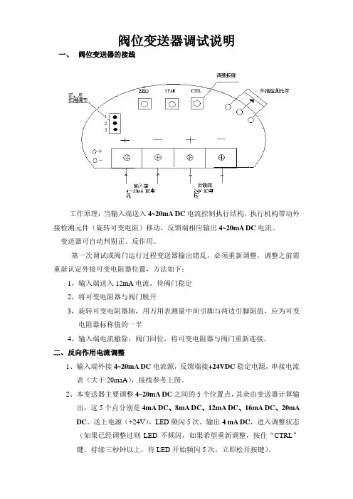
阀位变送器调试说明一、阀位变送器的接线工作原理:当输入端送入4~20mA DC电流控制执行结构,执行机构带动外接检测元件(旋转可变电阻)移动,反馈端相应输出4~20mA DC电流。
变送器可自动判别正、反作用。
第一次调试或阀门运行过程变送器输出错乱,必须重新调整,调整之前需重新认定外接可变电阻器位置,方法如下:1,输入端送入12mA电流,待阀门稳定2,将可变电阻器与阀门脱开3,旋转可变电阻器轴,用万用表测量中间引脚与两边引脚阻值,应为可变电阻器标称值的一半4,输入端电流撤除,阀门回位,将可变电阻器与阀门重新连接。
二、反向作用电流调整1、输入端外接4~20mA DC电流源,反馈端接+24VDC稳定电源,串接电流表(大于20maA),接线参考上图。
2、本变送器主要调整4~20mA DC之间的5个位置点,其余由变送器计算输出,这5个点分别是4mA DC、8mA DC、12mA DC、16mA DC、20mA DC。
送上电源(+24V),LED频闪5次,输出4 mA DC,进入调整状态(如果已经调整过则LED不频闪,如果希望重新调整,按住“CTRL”键,持续三秒钟以上,待LED开始频闪5次,立即松开按键)。
3、输入端送入4mA DC电流,确认阀门位置合适时,点动“CTRL”键,LED频闪1次,则该位置点调整完毕。
输出电流自动增加至8mA DC 4、输入端送入8mA DC电流,点动“CTRL”键,LED频闪1次,则该位置调整完毕。
输出电流自动增加至12mA DC5、依次送入12mA DC、16 mA DC并确认。
6、输入端送入20 mA D C电流,点动“CTRL”键,LED频闪8次,表示调整已完成,进入自动跟踪状态,并输出该位置点电流20 mA DC。
7、改变输入端送入电流,阀门位置改变输出电流值相应改变。
三、输出电流值调整1、由于电子元件特性的差异,每个变送器输出电流会有所不同,因此必须调整。
例如:8 mA DC位置点,输出为7.9 mA DC。
YT-1000电气阀门定位器性能介绍:
YT-1000电气阀门定位器(又称:气动阀门定位器)是调节阀的主要附件,通常与气动调节阀配套使用,它接受调节器的输出信号,然后以它的输出信号去控制气动调节阀,当调节阀动作后,阀杆的位移又通过机械装置反馈到阀门定位器,阀位状况通过电信号传给上位系统。
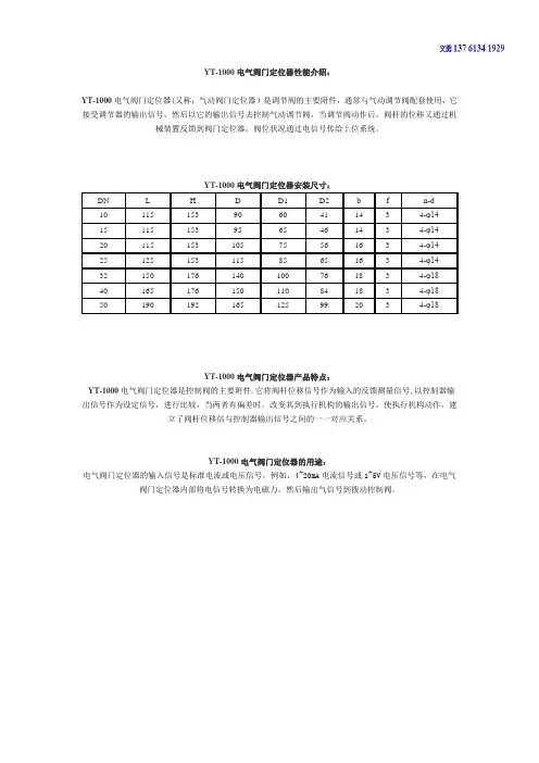
YT-1000电气阀门定位器安装尺寸:
DN L H D D1 D2 b f n-d
10 115 153 90 60 41 14 3 4-φ14
15 115 153 95 65 46 14 3 4-φ14
20 115 153 105 75 56 16 3 4-φ14
25 125 153 115 85 65 16 3 4-φ14
32 150 176 140 100 76 18 3 4-φ18
40 165 176 150 110 84 18 3 4-φ18
50 190 192 165 125 99 20 3 4-φ18
YT-1000电气阀门定位器产品特点:
YT-1000电气阀门定位器是控制阀的主要附件.它将阀杆位移信号作为输入的反馈测量信号,以控制器输出信号作为设定信号,进行比较,当两者有偏差时,改变其到执行机构的输出信号,使执行机构动作,建立了阀杆位移倍与控制器输出信号之间的一一对应关系。
YT-1000电气阀门定位器的用途:
电气阀门定位器的输入信号是标准电流或电压信号,例如,4~20mA电流信号或1~5V电压信号等,在电气阀门定位器内部将电信号转换为电磁力,然后输出气信号到拨动控制阀。
YTC-1000微机继电保护测试仪用户操作手册目录第一章继电保护测试仪说明 (3)1.1主要技术特点 (3)1.2主要技术指标 (4)1.3面板说明 (7)1.4硬件结构 (8)1.5仪器的操作使用 (9)1.6注意事项 (11)第二章继电保护测试仪使用方法 (13)2.1递变试验×7 (13)2.2递变试验×12 (18)2.3状态序列 (22)2.4谐波试验 (25)2.5整组试验 (30)2.6差动保护试验 (35)2.7频率试验 (41)2.8同期试验 (44)2.9电流-时间特性试验 (47)2.10电压-时间特性试验 (50)2.11故障再现 (53)2.12距离保护试验 (62)2.13零序保护试验 (67)2.14阻抗特性试验 (71)附录1:试验方法 (76)附录2:差动保护知识 (85)附录3:配置清单 (89)附录4:售后服务 (90)前言YTC1000微机继电保护测试仪是在参照中华人民共和国电力行业标准《继电保护微机型试验装置技术条件》(DL/T 624 ─ 1997)的基础上,广泛听取用户意见,总结目前国内同类产品优缺点,充分使用现代先进的微电子技术和器件实现的一种新型小型化微机继电保护测试仪。
它采用可单机独立运行,亦可联接其它电脑运行的先进结构,主机内置高性能工控机和高速数字信号处理器,真16位DAC 模块、新型模块式高保真大功率功放,自带TFT真彩色LCD显示器和嵌入式微机键盘。
既可以单机独立操作,也可以连接笔记本电脑操作。
操作功能强大,体积小,精度高。
既具有大型测试仪优越的性能、先进的功能,又具有小型测试仪小巧灵活、操作简便、可靠性高等优点,性能价格比高。
是继保工作者得心应手的好工具。
第一章继电保护测试仪说明1.1 主要技术特点微机型继电保护测试仪其主要特点表现为:●经典的Windows XP操作界面,人机界面友好,操作简便快捷,为了方便用户使用,定义了大量键盘快捷键,使得操作“一键到位”;●高性能的嵌入式工业控制计算机和8.4〞大屏幕高分辨力彩色TFT液晶显示屏,可以提供丰富直观的信息,包括设备当前的工作状态、下一步工作提示及各种帮助信息等;●配备有超薄型工业键盘和光电鼠标,可以象操作普通PC机一样通过键盘或鼠标完成各种操作;●配备有外接USB接口,可以方便地进行数据存取和软件维护;●无需外接其它设备即可以完成所有项目的测试,自动显示、记录测试数据,完成矢量图和特性曲线的描绘;●采用高性能D/A转换器,产生的波形精度高、线性好,并且具备良好的瞬态响应和幅频特性。
yt1000阀门定位器原理yt1000阀门定位器是一种用于调节控制阀门位置的设备,它通过测量和反馈阀门执行器的位置,实现对阀门的精确控制。
本文将介绍yt1000阀门定位器的原理及其工作过程。
一、原理概述yt1000阀门定位器基于电动阀门执行器和位置传感器的组合,实现对阀门位置的精确测量和控制。
其原理基于负反馈控制系统,通过持续的位置反馈和调整,使阀门保持在预设位置,从而实现对流体的流量和压力的精确调节。
二、工作过程1. 位置传感器yt1000阀门定位器内置了高精度的位置传感器,用于实时测量阀门执行器的位置。
传感器通常使用非接触式的技术,如霍尔传感器或磁敏传感器。
当阀门执行器移动时,传感器会感知到位置的变化,并将该信息传递给控制系统。
2. 控制系统yt1000阀门定位器配备了先进的控制系统,用于处理位置传感器的反馈信号,并根据设定值进行阀门位置的调整。
控制系统通常由微处理器和相关电路组成,能够实现高速、精确的控制。
3. 电动阀门执行器yt1000阀门定位器与电动阀门执行器紧密结合,通过控制执行器的运动来实现对阀门位置的调节。
电动阀门执行器通常由电机、齿轮传动装置和机械连接杆组成。
执行器接收控制系统的指令,通过电机的转动来改变阀门的开度。
4. 反馈控制yt1000阀门定位器的核心是负反馈控制系统。
在设定值和实际位置之间存在差值时,控制系统会根据该差值来调整阀门位置。
具体而言,如果阀门偏离设定值,控制系统会相应地发送指令,调整电动阀门执行器的运动,使阀门趋近于设定位置。
反之,当阀门接近预设位置时,控制系统将减小或停止对执行器的操作,以避免过冲。
三、优势与应用yt1000阀门定位器具有以下优势:1. 高精度控制:通过精确的位置反馈和调整,yt1000阀门定位器能够实现对阀门位置的精确控制,可满足对流量和压力更高要求的应用。
2. 快速响应:借助先进的控制系统,yt1000阀门定位器能够快速地对位置偏差进行反馈和调整,实现对流体的实时控制。
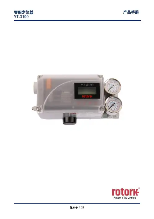
智能定位器产品手册YT-3100Rotork YTC Limited目录1引言 (5)1.1一般用户信息 (5)1.2制造商保修 (5)1.3防爆警告(仅适用于本质安全型定位器) (6)2产品说明 (7)2.1常规信息 (7)2.2主要特点和功能 (7)2.3标签说明 (8)2.4产品代号 (9)2.5产品规格 (10)2.6证书 (11)2.7部件和组件 (12)2.8产品尺寸 (13)3安装 (14)3.1安全 (14)3.2安装工具 (14)3.3直行程定位器安装 (15)3.3.1安全 (15)3.3.2标准反馈杆型定位器安装步骤 (16)3.4角行程定位器安装 (20)3.4.1组件 (20)3.4.2角行程支架信息 (21)3.4.3角行程定位器安装步骤 (22)4连接 -空气 (24)4.1安全 (24)4.2供给压力条件 (24)4.3管路连接 (24)4.4连接 - 执行管路 (25)4.4.1单作用执行器 (25)4.4.2双作用执行器 (25)5连接 - 电源 (26)5.1安全 (26)5.2连接 (26)5.3接地 (27)6调节 (28)6.1孔口件安装 (28)7选配型副PCB安装 (29)7.1安装步骤 (29)8维护 (30)8.1供给压力 (30)8.2密封件 (30)9自动校准和PCB操作 (31)9.1警告 (31)9.2LCD显示器和按钮 (31)9.2.1LCD显示器和符号 (31)9.2.2按钮和功能 (32)9.3菜单层级 (33)9.4运行模式监控 (34)9.5配置和操作 (35)9.6校准(CALIb) (37)9.6.1动作类型(SINGLE / dOUBLE) (38)9.6.2自动校准1(AUTO 1) (38)9.6.3自动校准2(AUTO 2) (39)9.6.4自动校准3(AUTO 3) (40)9.6.5行程零点(TVL ZERO)和行程终点(TVL ENd) (41)9.7手动操作(MAN OPER) (42)9.7.1通过设置位置进行手动操作(MAN SP) (42)9.7.2利用MV进行手动操作(MAN MV) (42)9.8控制参数(CTL PARM) (43)9.8.1死区(dEAdbANd) (43)9.8.2向前P参数(KP UP)和向后P参数(KP dN) (43)9.8.3向前积分时间参数(TI UP)和反向积分时间参数(TI dN) (44)9.8.4向前D参数(Kd UP)和向后D参数(Kd dN) (44)9.8.5自动死区模式(AUTO db) (44)9.8.6性能模式(PER STbL / NORM / FAST) (45)9.9输入配置(IN CFG) (46)9.9.1信号方向(SIG NORM / REVS) (46)9.9.2分程模式(SPLIT 4.20 / 4.12 / 12.20 / CSt) (47)9.9.3自定义分程模式零点(CST ZERO) (47)9.9.4自定义分程模式终点(CST ENd) (48)9.9.5阀门流量特性曲线(CHAR LIN / EQ / USER 5P / USER 21P) (48)9.9.6用户设置5个特性点(USER 5P) (49)9.9.7用户设置21个特性点(USER 21P) (50)9.9.9用力关闭(TSHUT CL) (52)9.10输出配置(OUT CFG) (53)9.10.1位置发送器方向(PTM NORM / REVS) (53)9.10.2位置发送器零点/终点(PTM ZERO / ENd) (54)9.10.3反算(bACKCAL oFF / on) (55)9.11设备配置(dEV CFG) (56)9.11.1动作设置(ACT) (56)9.11.2直行程差值(ITP oFF / on) (57)9.11.3参数锁定(Write Protect, W UNLOCK / LOCK) (57)9.11.4实际位置查看模式(View Mode, VI NORM / REVS) (58)9.11.5出厂重置(dEFAULT oFF / on) (58)9.11.6定位器自测试(SELFTEST) (59)9.12诊断模式(dIAGNd) (60)9.12.1默认警报设置 (60)9.12.2设备状态(dS) (61)9.12.3重置警报状态(RST ALRM oFF / on) (62)9.12.4查看事件日志(EVT LOG) (63)9.13位置信息(INFO) (64)9.14自动校准过程中显示的错误代码 (66)9.15状态和警报代号 (67)10主要软件地图 (68)1 引言1.1 一般用户信息感谢您购买Rotork YTC Limited产品。
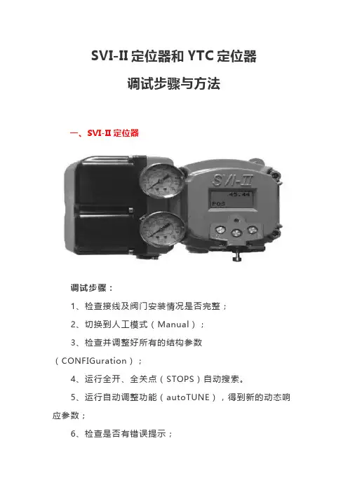
SVI-II定位器和YTC定位器调试步骤与方法一、SVI-II定位器调试步骤:1、检查接线及阀门安装情况是否完整;2、切换到人工模式(Manual);3、检查并调整好所有的结构参数(CONFIGuration);4、运行全开、全关点(STOPS)自动搜索。
5、运行自动调整功能(autoTUNE),得到新的动态响应参数;6、检查是否有错误提示;7、手动操作看看是否可以正常运行;退出人工状态,回到自动控制状态。
菜单流程:接通信号源后,将输入信号调节到12mA。
系统会进行自检,然后进入交替显示阀位和输入信号的值。
此时系统有可能处于人工或自动的状态,取决于上次运行断电前的状态。
如果屏幕显示阀位时使用(POS-M)说明处于人工状态;如果显示阀位时使用(POS)说明处于自动状态。
然后按照流程图操作即可完成设定。
二、YTC定位器调试步骤:1、条件:①稳定的气源压力≥0.3MPa(角行程定位器压力≥0.5MPa)②4-20mA信号输入设备2、调试:①打开定位器前盖,打开电源接线盒。
②把稳定气源接入过滤减压阀并密封严紧。
③区分正负输入端接好信号输入设备。
④打开气源开关,向下调节调“0”旋钮,直至排气压力表指针不为0,然后反方向缓慢旋转调“0”旋钮,使压力表指针刚好处于0位置。
⑤输入25%(8mA)、50%(12mA)、75%(16mA)、100%(20mA)信号,观察指针下降(上升)行程:A、若单次行程超过刻度盘的1/4,说明定位器量程过大,此时应调节量程调节旋钮(先松开螺丝,然后调节下方的旋钮,向“—”方向调节。
根据实际情况确定调节的程度,单次微调,边试边调)。
B、若单次行程过小或不足刻度盘的1/4,说明定位器量程过小,操作与A相同,方向相反。
⑥每次调节量程调节旋钮后,重新进行试验,若实际行程与理论行程差距仍然很大,则再调节量程调节旋钮;若实际行程与理论行程差距较小,则调节调“0”旋钮,使指针移动到对应的刻度上,再输入信号观察指针移动是否正确。
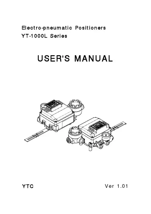
Electro-pneumatic PositionersYT-1000L SeriesUSER'S MANUALYTC Ver 1.01Table of ContentsIntroduction3 Manufacturer Warranty3 Product Description4 Main Features and Functions4 Operation Logic4 Label Description5 Suffix Symbol5 Specification6 Parts and Assembly7 Dimension8 YT-1000L: Explosion-Proof Type8 YT-1000L: Intrinsically Safe Type8 Installation9 Safety Waring9 Tools for Installation9 YT-1000L Installation9 Piping Connection12 Supply Pressure Condition12 Pipe Condition12 Piping Connection with Actuator12 Power Connection13 Connection - Connection Port13 Connection - Cable Gland13 Connection - Power14 Connection - Ground14 Adjustment15 Adjustment - Zero15 Adjustment - Span15 Adjustment - A/M Switch (Automatic/Manual)15 Adjustment - Seat Adjuster15 Adjustment - Orifice16 Troubleshooting17IntroductionThank you for choosing YTC product. Each product is fully inspected after the production to offer you the highest quality. In order to fully utilize the product, we strongly recommend users to read this manual carefully and understood.z The manual should be provided to the end user.z The manual can be changed or revised without any prior notice. Any changes in product's specification, structure, and/or any components may not result immediate revised version of the manual.z The manual should not be duplicated or reproduced for any purpose without any approval from Young Tech Co., Ltd, South Korea.Manufacturer Warranty- For the safety, it is imperative to follow instructions in the manual. It is not manufacturer's liability for any damages which caused by users' negligences.- It is not manufacturer's liability for any damages or accidents which resulted by any alteration or modification of the product and parts. If alteration ormodification is necessary, please contact the manufacturer directly.- Manufacturer warrants the product from the date of original retail purchase of the product for one (1) year, except as otherwise stated.- Manufacturer warranty will not cover the products that the product have been subjected to abuse, accident, alteration, modification, tampering, negligence,misuse, faulty installation, lack of reasonable care, repair or service in any waythat is not contemplated in the documentation for the product, or if the modelor serial number has been altered, tampered with, defaced or removed;damages that occurs in shipment, due to act of God, failure due to powersurge, and cosmetic damage. Improper or incorrectly performed maintenance or report voids this Limited Warranty.- For detailed warranty information, please contact the corresponding local Young Tech Co., Ltd office or main office in South Korea.Product DescriptionMain Features and Functionsz It is designed for high durability and performance in high vibration environment.z Durability has proven after testing of 1 million times, at least.z Response time is very short and accurate.z Simple part change can set 1/2 Split Range.z It is economical due to less air-consumption.z Direct/Reverse action can be set easily.z Zero & Span adjustment process is simply.nozzle(③) and the flapper(②) increases, which results pressure in upper spool(⑤) exhaustion. This would cause spool(⑤) to rise upward. As the spool(⑤) rises, the air pressure will be supplied to the actuator(⑩). As the actuator's inner pressure increases, the actuator stem(⑫) will move. The movement will be transferred to cam(⑭) and pulls the span spring(⑮). The span spring(⑮)'s force will be balanced with torque motor(①), and this would cause to move flapper(②) to the normal position and reduce the gap between the nozzle(③). As the air pressure exhaustion level decreases through the nozzle(③), the pressure level in upper spool(⑤) increases again. The spool(⑤) would come back to the normal position and block the seat(⑦) which would lead to block the supply air from the actuator(⑩). When the actuator(⑩) stops the movement, the positioner would come back to the normal position. <Figure 1>Suffix SymbolYT-1000L series follows suffix symbols as follows.YT-1000L════════════════════════════════Motion Type S :LinearD :Double════════════════════════════════Explosion Proof m :Ex dm IIB T5C :Ex dm IIC T5:Ex ia IIB T6in :Non-Explosion════════════════════════════════Feedback Lever 1 :10 ~ 40mm:30∼ 70mm23 :60 ∼ 100mm4 : 100 ∼ 150mm════════════════════════════════Orifice 1 : Ø1Ø22:3 : None════════════════════════════════Connection Type 1 :PT2 :NPT════════════════════════════════Ambient Temperature S :-20 ~ 70℃H :-20 ~ 120℃L :-40 ~ 70℃════════════════════════════════* For special specification, please contact our sales department.Specification* Tested under ambient temperature of 20℃, absolute pressure of 760mmHg, and humidity of 65%.Please contact us for more detailed specification.* 1: For 1/2 Split Control, it can be applied by adjusting zero and span.*2: For inquiry regarding strokes under 10mm or above 150mm, please contact YTC.* 3: YT-1000L has different types of explosion proof certificates. Please make sure to check explosion proof grade.Parts and AssemblyInstallationSafety WarningWhen installing positioner, please ensure to read and follow safety instruction.z All input and supply pressure to valve, actuator, and other related devices must be turned off.z Use bypass valve or other equipment to avoid entire system "shut down."z Make sure there is no remaining pressure in the actuator.Tools for installation①Hexagonal wrench②Screw drivers (+) & (-)③Spanners for hexagonal-head boltsYT-1000L installationYT-1000L should be installed on linear motion valve such as globe valve or gate valve using spring return type diaphragm or piston actuator. Before installation, be sure to check for following installation components.①YT-1000L main body②Feedback lever and lever spring③Flange nut (bottom side of YT-1000L)④4 pcs. of hexagon head bolts (M8 X 1.25P)⑤4 pcs. of M8 plate washerInstallation Steps(1)Proper bracket must be made in order to attach positioner on the actuator yoke.Please consider following when making a bracket.① Feedback lever should be leveled at 50% of valve stroke. (Refer to Step 7)② Feedback lever connection bar of actuator clamp should be installed at the position that the valve stroke and numbers which indicated on the feedback lever must be fitted. (Refer to Step 8)produced in earlier step, by using bolts.<Figure 2> Please refer to backside of theavailable. Please contact YTC sales department.(3) Attach YT-1000L (with bracket) to the actuator yoke - DO NOT TIGHTENCOMPLETELY.(4) Connect YT-1000L feedback lever to the actuator clamp. The gap on theYT-1000L feedback lever is 6.5mm. The connection bar thickness should be less than(7) If connection bar does not point at 50% point, then adjust bracket or feedbacklink bar position. Failure to position at 50% would lower the linearity of the positioner. <Figure 6><Figure 6>(8) Check valve stroke. The stroke numbers are indicated on the feedback lever.Position connection bar at the number on the feedback lever according to the valve stroke. <Figure 7> To adjust, move the bracket or connection bar.Stroke 30mmStroke 70mm<Figure 7>NoteAfter instaling YT-1000L, operate the valvefrom 0% to 100% stroke by using air filterregulator on the actuator. Both of 0%and 100%, the feedback lever should nottouch the lever stopper, which is locatedon the backside of YT-1000L. <Figure 8>If the feedback lever touches the leverstopper, YT-1000L should be installedfurther away from the center of the yoke. <Figure 8>(9) After the proper installation, tighten all of the bolts on the bracket, thefeedback lever, and the connection bar.Piping ConnectionNotez To avoid entering moisture, oil, or dust into the product, please carefully make selection of supply pressure compressor.z It is recommended to attach air filter regulator before supply port of YT-1000.Supply Pressure Condition①Dry air with at least 10℃ lower than ambient temperature.②Avoid from dusty air. Filter can only sort 5 micron or larger.③Avoid any oil.④Comply with ANSI/ISA-57.3 1975(R1981)이나 ISA S7.3-1975(R1981).⑤Not to be used beyond the range of 1.4 - 7 kgf/cm2(140 - 700 kPA).⑥Set air filter regulator's supplied pressure 10% higher than actuator's spring rangepressure.Pipe Condition①Make sure inside of pipe is emptied.②Do not use pipeline that is squeezed or has hole.③To maintain flow rate, use the pipeline that has more than 6mm inner diameter.(10mm outer diameter)④Do not use extremely long pipeline system. It may affect flow rate due to thefriction inside of the pipeline.Piping connection with actuatorYT-1000 series single acting type is set to use OUT1 port. OUT1 port should be connected with supply pressure port from actuator when using single acting type of spring return actuator. For double acting type, the piping connection can be changedConnection - Power①Open terminal box cover.②Locate the poles and connect them properly. Make sure to fasten the connection.③Close back the terminal box cover. <Figure 15>Safety WarningYT-1000L designed under intrinsically safe procedures and restriction. However, intrinsically safe system can be damaged from electronic energies from other electronic devices. To avoid any system damages, please read the following.z Differentiate intrinsically safe type circuit with other types of circuit clearly.z Apply proper protection device to reduce frictions.z If possible, minimize the use of inductance and capacitance. If they must be used, set the devices at lower level than the maximum level.z Protect the wires from damages.zConnection - Ground① Open positioner's body cover.②properly. <Figure 16>AdjustmentAdjustment - Zero Point①and system must be taken account. Please refer to<Figure 17> for increase/decrease of the zero point.②When single acting actuator with spring is used, please check if the pressure levelwhich is indicated on the positioner is same to the supplied pressure level.Adjustment - Span①towards '-' direction. <Figure 18>②until both points are properly set.③Adjustment - A/M Switch (Auto/Manual)①A/M switch adjusts the valve operation toautomatic or manual.②When produced, YT-1000L is set at"A(Automatic)". If user prefers the positioner'ssetting as "M(Manual)," the setting can be<Figure 19>③If it is set as "M(Manual)", the air pressure will besupplied to the actuator directly. Always set backto "A(Automatic)" after setting change.④actuator is used, A/M Switch will not operate. <Figure 19>Adjustment - Seat Adjuster①Seat Adjuster is set according to the customer's request before the positioner isdelivered. Please do not adjust the Seat Adjuster.②Seat Adjuster is used for double acting actuator always and adjusted when theAdjustment - Orifice①If the size of actuator is too small relative to the flow rate, positioner can havehunting. In order to avoid hunting, orifice can be used. There are three types of the orifice.Actuator Size Orifice Size Suffix Symbol90 cm3less∅1190 ~ 180 cm3∅22180 cm3more none3②Remove the o-ring from OUT1 and OUT2 port and insert appropriate orifice. AfterTROUBLESHOOTING▶ Positioner does not respond to the input signal.(1)Check supply pressure level. The lever must be at least 1.4 kgf/cm2. Forspring-return type of actuator, the supply pressure level has to be larger than the spring's specification.(2)Check if input signal is properly supplied to the positioner. The signal should be4~20mA DC.(3)Check if zero point or span point is properly set.(4)Check if the positioner's nozzle has been blocked. Also, check if the pressure issupplied to the positioner and the pressure is being exhausted through the nozzle.If the nozzle has been block by any substances, please send the product forrepair.(5)Check if feedback lever has been installed properly.▶ The pressure of OUT1 reaches exhausting pressure level and does not come back down.(1)Check A/M Switch. If the switch has been damaged, replace the switch or pilotrelay valve.(2)Check for a gap or damages between the nozzle and the flapper. If damaged,please send the product to YTC for repair.▶ The pressure is exhausted only by A/M Switch.(1)Check if the positioner's nozzle has been blocked. Also, check if the pressure issupplied to the positioner and the pressure is being exhausted through the nozzle.If the nozzle has been blocked by any substances, please send the product toYTC for repair.▶ Hunting occurs.(1)Check if safety spring has been displaced. (Next to Pilot relay valve)(2)Check if the size of actuator is too small. If so, insert an orifice in order toreduce the pressure flow rate.(3)Check if there is any friction between the valve and the actuator. If so, increaseactuator's size or reduce the friction level.▶ Actuator only operates by On/Off.(1)Check actuator and positioner's acting type. Air pressure exhausts fromYT-1000L's OUT1 port as input signal level increases. Therefore, it is standard to connect to OUT1 port when single actuator is used. Make sure the spanadjustment is properly set according to the valve system.▶ Linearity is too low.(1)Check if positioner is properly positioned. Especially check if the feedback lever isparallel to the ground at 50% point.(2)Check if zero and span point have been properly adjusted. If either one of valuesis being adjusted, another one must be re-adjusted as well.(3)Check if supply air pressure level is stable from the regulator. If the level isunstable, the rgulator must be replaced.▶ Hysteresis is too low.(1)In case of double acting actuator, check if seat adjustment has been properlyperformed. Please contact YTC for any further inquiries regarding the seatadjustment.(2)Backlash can occur when the feedback lever and lever spring are loosen. Toavoid backlashing, please adjust the lever spring.(3)Check if the connection bar to the feedback lever is tightly fastened.Young Tech Co., LtdAddress:#662-8 Pungmu-Dong, Gimpo-City, Kyunggi-Do, South KoreaTelephone: +82-31-986-8545Fax: +82-31-986-2683Website: http://www.ytc.krUser Manual and other information on the documents are subjected to change without any notice. Please visit website for most updated information. Printed Date: June, 2007。
YT-1000L型电-气阀门定位器YT-1000L型电-气阀门定位器用于采用4-20mA或等信号范围的模拟信号的电动控制器及控制系统的气动回转阀执行机构的回转操作。
1.结构2.安装2.1安装到执行机构的范例2.2反馈杆的连接1.安装到当输入信号为50%时阀杆和反馈杆成直角的位置上。
2.安装到偏差角在10度-30度内位置上。
2.3正向动作与反向动作〈正向动作〉〈反向动作〉2.4通气管的连接2.1.用管子彻底清除杂物。
2.用洁净气体彻底清除潮气和尘埃。
3.用YT-200过滤调节器不断保持供气压力。
4.在将双向动作型作为单向动作型使用时,不是堵塞OUT1就是堵塞OUT2,而且还要拆下压力表来断开其连接。
4.电气接线1.分别将调整器的(+)(-)输出端和定位器接线盒的(+)(-)输入断连接起来。
2.至于防爆型,压力密封导线管线连接型和压力密封充填型都可适用。
(1)在压力密封充填型中使用电缆密封套(电缆外径=90-11)。
(2)在导线管线连接型中使用PF1/2(G1/2)规格。
3.关上接线盒盖,锁上锁定螺丝。
4.在接线板上有只备用螺栓。
5.调整1.在开始调整前检查下列。
检查管道与压力输送口和OUT1及OUT2口正确连接。
2.检查导线与(+)、(-)极和接地端正确连接。
3.检查执行机构与定位器牢固连接。
4.检查导阀自动/手动转换开关螺丝松紧(顺时针完全紧固)。
5.检查内反馈跨距调整杆被安装到正确的位置上(正向或反向)6.检查凸轮面(正向或反向)的正确使用和发兰盘螺母牢固锁紧。
5-1零位调整1.将信号设定在冲程开始信号(4mA),然后顺时针或逆时针转动零位调整器。
2.如果是弹簧执行机构,检查它是否设在零位标准压力上。
如否,则重复进行零点调整。
5-2跨距调准1.调整跨距范围以便执行机构分别按0%和100%输入信号停在冲程的0%和100%位置上。
2.检查零位,重复进行零位跨距调整。
零位跨距调整采用1/2分隔范围。
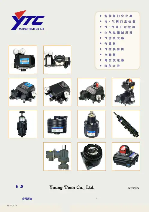
●智能阀门定位器●电- 气阀门定位器●气 - 气阀门定位器●空气过濾减压阀●气动放大器●气锁阀●气控换向阀●电磁阀●阀位变送器●限位开关目录Young Tech Co., Ltd. Rev.C0804公司历史 3认证书4,5产品目录智能阀门定位器 6 YT-2300系列(本安型)7YT-2350系列(不锈钢型)8YT-2301L(直行程远传型)9YT-2301R(角行程远传型)10 YT-2400系列(隔爆型)11 YT-2500系列(断信号保位型)电-气阀门定位器12 YT-1300系列(电子式)直行程 13 YT-1000L角行程14 YT-1000R(标准型)15 YT-1000R(圆顶指示器)16 YT-1000R + 阀位变送器(内置型)17 YT-1000R + 阀位变送器(外置型)18 YT-1000R + 限位开关(内置型)19 YT-1000R + 限位开关(外置型)20 YT-1000R + 阀位变送器+ 限位开关(内置型)21 YT-1000R + 阀位变送器+ 限位开关(外置型)气-气阀门定位器直行程22 YT-1200L角行程23 YT-1200R空气过濾减压阀24 YT-200, YT-205气动放大器25 YT-300,YT-305, YT-310, YT-315,YT-320气锁阀26 YT-400, YT-405气控换向阀27 YT-500,YT-505, YT-510, YT-515电磁阀28 YT-700阀位变送器29 PTM-5VL,R(本安型)30 PTM-6VL,R(隔爆型)31PTM-6VR + 限位开关(隔爆型)限位开关32 YT-85033 YT-860(隔爆型)支架,反馈杆 34351996.01 成立YoungTech co.,Ltd. 1996.05 生产电-气阀门定位器YT-1000L,R 1996.08 生产空气过濾减压阀YT-200 ,220 1997.07 生产气动放大器 YT-3001997.12 生产气-气阀门定位器YT-1200L,R 1998.02 生产阀位变送器 PTM-5L,R1998.08 电-气阀门定位器YT-1000L,R 获得CE 证书 1999.04 生产智能阀门定位器 YT-2000L,R 1999.06 生产气动放大器YT-3101999.10 电-气阀门定位器YT-1000L,R 获得EM 证书(韩国政府颁发) 2000.01 获得ISO 9001认证2000.04 获得风险投资企业认证 (韩国政府颁发) 2000.07 生产气锁阀YT-4002000.11 生产气控换向阀YT-500,510 2001.01 生产阀位变送器PTM-6L, R 2001.05 建新工厂2001.08 电-气阀门定位器YT-1000L,R 获得KEMA EExmdIIBT4防爆等级证书 2001.11 电磁阀YT-700,710,720 获得ExdIICT6防爆等级证书2002.02 OEM 生产日本本山(Motoyama )公司的EA91,EA90型电气阀门定位器 2002.05 加入HART 协会2002.07 获得出口有望中小型企业证书(韩国政府颁发) 2002.09 生产不锈钢型空气过滤减压阀YT-205 2003.02 升级为ISO 9001:20002003.10 电-气阀门定位器YT-1000L,R 获得ATEX EEx dm IIB T5防爆等级证书 2003.11 生产智能阀门定位器YT-2003系列 2004.01 设立研究所2004.01 生产阀位变送器PTM-5V,PTM-6V 系列 2004.11 生产智能阀门定位器YT-2400系列2005.01 电-气阀们定位器YT-1000系列获得CSA Ex md IIB T5防爆等级证书 2005.01 电-气阀们定位器YT-1000L 系列获得日本JIS IIB T5防爆等级证书 2005.01 生产电子式阀门定位器YT-1300系列2005.08 生产不锈钢智能阀门定位器YT-1350系列和电子式阀门定位器YT-1350系列 2005.09 获得韩国水利核电站供货资质。
C1000调节器操作说明
一、按键功能说明
1、功能键:切换功能画面
2、确认键:切换追忆方式、手自动切换
3、增加键:(通道键):切换通道、在定位时增加追忆时间
4、减少键:(时标键):修改时标、在定位追忆时减少时间
5、左移键:向前追忆
6、右移键:向后追忆
二、监控操作
PV——测量值
SV——工艺给定值
MV——调节阀阀位值(开度)
A——表示自动
M——表示手动
1、给定值的修改:在自动(A)模式下,按增加键和右移键可以修改给定值。
2、手动/自动切换:使用左移键可以实现手动/自动切换功能。
3、手动调节输出:在手动(M)模式下,按增加键和减少键可改变阀位输出值。
三、提示
1、在手动位置时:给定值和阀位值始终相等,属于正常现象。
2、操作工一般情况下只需使用三个键,即:增加键、减少键、左移键。
3、未涉及到的内容,操作人员切勿乱动,一旦按错键,就有可能进入仪表组态程序,此时不可继续按动其它键,请立即通知仪表工现场处理。
仪表车间
2006-3-25。
YTC定位器调试步骤:
1、条件:
①稳定的气源压力≥0.3MPa(角行程定位器压力≥0.5MPa)
②4-20mA信号输入设备
2、调试:
①打开定位器前盖,打开电源接线盒。
②把稳定气源接入过滤减压阀并密封严紧。
③区分正负输入端接好信号输入设备。
④打开气源开关,向下调节调“0”旋钮,直至排气压力表指针不为0,然后反方向缓慢旋转调“0”旋钮,使压力表指针刚好处于0位置。
⑤输入25%(8mA)、50%(12mA)、75%(16mA)、100%(20mA)信号,观察指针下降(上升)行程:
A、若单次行程超过刻度盘的1/4,说明定位器量程过大,此时应调节量程调节旋钮(先松开螺丝,然后调节下方的旋钮,向“—”方向调节。
根据实际情况确定调节的程度,单次微调,边试边调)。
B、若单次行程过小或不足刻度盘的1/4,说明定位器量程过小,操作与A相同,方向相反。
⑥每次调节量程调节旋钮后,重新进行试验,若实际行程与理论行程差距仍然很大,则再调节量程调节旋钮;若实际行程与理论行程差距较小,则调节调“0”旋钮,使指针移动到对应的刻度上,再输入信号观察指针移动是否正确。
注:通过量程调节旋钮和调“0”旋钮的配合来调节量程和行程,已达到调试的目的。
注意事项:
(1)当输入信号为20mA时,定位器排气压力必须>3公斤(球阀5公斤),一般为3.2-4公斤。
若压力不足则调节阀开启/关闭不严,无法正常工作。
(2)气开阀:当输入信号为0时,排气压力必须为0,否则阀门没有完全关闭。
Product ManualCVS 1000L Electro-Pneumatic Linear Positioner INTRODUCTIONThank you for choosing the YT-1000L. Each productis fully inspected after production to offer you thehighest quality. In order to fully utilize the product, westrongly recommend users to read this manualcarefully.∙ The manual can be changed or revised withoutany prior notice. Any changes in the product’sspecification, structure and/or any componentsmay not result in an immediate revised version ofthe manual.∙ The manual should not be duplicated orreproduced for any purpose without the approvalof CVS Controls Ltd.MANUFACTURER WARRANTY-For safety, it is imperative to follow instructions in the manual. The manufacturer is not liable for any damages caused by the users negligence.-The manufacturer is not liable for any damages or accidents as a result of alterations or modifications made to the product or parts. If alterations or modifications are required, please contactCVS Controls Ltd.-The manufacturer warrants the product from the original date of purchase for one (1) year, except as otherwise stated.-The manufacturer warranty will be considered void should the product be subjected to abuse, faulty installation, lack of reasonable care, repair or service in any way, that is not contemplated in the documentation of the product, or if the model or serial number has been altered, tampered with, defaced, or removed; damages that occur in shipment, due to the act of God, failure due to power surge, and cosmetic damage. Improper or incorrectly performed maintenance also voids the Limited Warranty.PRODUCT DESCRIPTIONMain Features and Functions∙ It is designed for high durability and performance in high vibration environments.∙ Proven Durability.∙ Short and accurate response time.∙ Simple part change can set a 1/2 Split Range.∙ Economical due to less air-consumption.∙ Direct/Reverse action can be easily set.∙ Simple zero and span adjustment process.∙Easy feedback connection.CVS Controls Ltd.Product Manual: CVS Rack & Pinion ActuatorOperation LogicAs the input signal is increased, the flapper (2) get pushed by the force of the torque-motor (1). As the gap between the flapper (2) and the nozzle (3) increases, air pressure bleeds from the pilot valve (4) and the spool (5). As a result, the spool (5) rises and simultaneously opens the seat (7). This allows air pressure to discharge through port OUT1 to the actuator (10). As the actuators inner pressure increases, the actuator stem (12) will move, pushing on the feedback lever (13). This movement is transferred to the cam (14) and pulls on the feedback spring (16). At the point of balanced force exerted by the input signal and the feedback spring, the gap between the flapper (2) and the nozzle (3) will decrease, stopping the movement to the actuator.CVS Controls Ltd.Product Manual: CVS Rack & Pinion Actuator Specification* 1: For 1/2 Split Control, it can be applied by adjusting zero and span.* 2: For inquiries regarding strokes under 10mm or above 150mm, please contact CVS Controls Ltd.Parts and AssemblyDimensionsCVS Controls Ltd.Product Manual: CVS Rack & Pinion ActuatorZERO UNIT TORQUE MOTOR BASE BODY JUNCTION BOXCOVER PILOT VALVE FEEDBACK SHAFT SPAN UNITVENT UNIT FEEDBACK LEVER224.3132.36 Conduit EntryPT(NPT) 1/2 PF(G) 1/2Out 2NONE45122166.2-M8x1.25P452327 32.54-M8x1.25P35.591.8837.280.253326.543.5GaugePT(NPT) 1/8OUT 1PT(NPT) 1/4SupplyPT(NPT) 1/4INSTALLATIONSafety WarningWhen installing the positioner, please ensure you read and follow the safety instructions.∙ All input and supply pressure to valve, actuator, and other related devices must be turned off.∙ Use the bypass valve or other equipment to avoid an entire system “shut down”.∙ Make sure there is no remaining pressure in the actuator.YT-1000L InstallationYT-1000L should be installed on a linear motion valve such as a globe or gate valve using a spring return type diaphragm or piston actuator. Before installation, be sure to check for the following installation components.1. YT-1000L main body2. Feedback lever and lever spring3. Flange nut (bottom side of YT-1000L)4. 4 pcs. of hexagon head bolts (M8 X 1.25P)5. 4 pcs. of M8 plate washerInstallation Steps:1. A proper bracket must be made in order to attach the positioner on the actuator yoke. Please consider the following when making a bracket.i) Feedback level should be leveled at 50% of the valve stroke. (Refer to step 7.)ii) Feedback lever connection bar of actuator clamp should be installed at the position that the valve stroke and number, indicated on the feedback, should be fitted. (Refer to step 8.)2. Attach YT-1000L to the bracket, which was produced in the earlier step, by using bolts. (Figure 2) Please refer to the backside of the product for size of bolts. The standard size of bolt is M8 X 1.25P.3. Attach YT-1000L (with bracket) to the actuator yoke. DO NOT TIGHTEN COMPLETLEY.4. Connect YT-1000L feedback lever to the actuator clamp. The gap on the YT-1000L feedback lever is6.5mm. The connection bar thickness should be less than 6.3mm. (Figure 3)5. Connect the air filter regulator to the actuator tem-porarily. Set supply pressure of the regulator in orderto position the actuator clamp at 50% of the valve stroke.(Figure 4 next page)CVS Controls Ltd.Product Manual: CVS Rack & Pinion ActuatorMax.6.36.5mm506. Insert connection bar into the YT-1000L feedback lever. The connection bar should be inserted at the 50% point on the feedback lever, which would help to reduce hysteresis.(Figure 5)7. If the connection bar does not point at the 50% point, then adjust the bracket or feedback link bar position. Failure to position at 50% would lower the linearity of the positioner.(Figure 6) 8. Check valve stroke. The stroke numbers are indicated on the feedback lever. Position the connection bar at the number on the feedback lever according to the valve stroke. To adjust, move the bracket or connection bar.(Figure 7)Stroke 70mmNOTE: After installing the YT-1000L, operate the valve from 0% to 100% stroke by using the air filter regulator on the actuator. Both at 0% and 100%, the feedback lever should not touch the lever stopper, which is located on the backsideof the YT-1000L.(Figure 8)If the feedback lever touches the lever stopper, YT-1000L should be installed further away from the center of the yoke.9. After the proper installation, tighten all the bolts on the bracket, the feedback lever, and the connectionbar.CVS Controls Ltd.Product Manual: CVS Rack & Pinion ActuatorYT-20040 50 6050%90°20 30 40 50 6040 50 60 70 20 3070 Stroke 30mmPIPING CONNECTIONNOTE:To avoid moisture, oil, or dust from entering the product, please carefully select the supplypressure compressor.Supply Pressure Condition1. Dry air with at least 10°C lower than ambient temperature.2. Keep away from dusty air. Filter can only sort 5 micron or larger.3. Avoid oil.4. Comply with ANSI/ISA-57.3 1975(R1981).5. Not to be used beyond the range of1.4 - 7 kgf/cm2 (20 - 100 Psi).6. Set air filter regulator’s supplied pressure 10% higher than actuator’s spring range pressure.Pipe Condition1. Make sure the inside of the pipe is empty.2. Do not use pipeline that is squeezed or has holes.3. To maintain flow rate, use the pipeline that has more than a 6mm inner diameter.4. Do not use an extremely long pipeline system. It may affect flow rate due to the friction inside the pipeline.Piping Connection with ActuatorYT-1000 series single acting type is set out to use OUT1 port. OUT1 port should be connected with the supply pressure port from the actuator when using single acting type spring return actuator. For double acting, the piping connection can be changed due to the operation direction. Please refer to the following diagrams when piping.(Figures 9 - 11)CVS Controls Ltd.Product Manual: CVS Rack & Pinion ActuatorOUT1OUT1SUP.AIRSUPPLYYT-200OUTAIRSUPPLYYT-200OUTOUT 1OUT 2OUT 2 SUP.OUT 1OUT 1OUT 2AIRSUPPLYAIRSUPPLYOUT 2SUP. OUT 1INPUTSIGNAL4~20mADIRECTACTIONREVERSEACTIONOUT 2OUT 1OUT 2SUP. OUT 1POWER CONNECTIONConnection - Connection Port1. Connection port size is 1/2” NPT.NOTE: REFER TO THE CANADIAN ELECTRICAL CODE FOR HAZARDOUS WIRING METHODS.Connection Power1. Open the terminal box cover.2. Locate the poles and connect them properly. Make sure to fasten the connection.3. Close the terminal box cover. (Figure15)ADJUSTMENTAdjustment - Zero Point1. Set supply signal at 4mA or 20mA and rotate adjuster clockwise or counter-clockwise to adjust the actuator’s initial point. When setting the initial point, the specification of valve and system must be taken into account. Please refer to Figure 17 for increase/decrease of the zero point.2. When a single acting actuator with spring is used, please check if the pressure level, which is indicated on the positioner, is the same as the supplied pressure level.CVS Controls Ltd.Product Manual: CVS Rack & Pinion ActuatorUpper SideLower SideGroundRed (+)Black (-)Adjustment - Span1. After setting zero, supply 20mA or 4mA of signal. Check the actuator’s stroke. If the stroke is too low, adjust the span towards the (+) direction.If the stroke point is too high, adjust the span towards the (-) direction. (Figure 18)2. Changing span points affects the zero point setting, so the zero setting must be set again. After setting zero point, confirm the span point. This step must be repeated until both points are properly set.3. After setting is completed, tighten lock screw.Adjustment - A/M Switch (Auto/Manual) 1. A/M switch adjusts the valve operation to automatic or manual.2. When produced, YT-1000L is set at “A(Automatic)”. If user prefers the positioner setting as “M(Manual)”, the setting can be changed by turning the switch counter-clockwise. (Figure 19)3. If it is set as “M(Manual)”, the air pressure will be supplied to the actuator directly. Always set back to “A(Automatic)” after setting change.4. If OUT2 in single acting actuator or double acting actuator is used, the A/M switch will not operate. Adjustment - Seat Adjuster1. Seat adjustment is set according to the customers request before the positioner is delivered. Please do not adjust the seat adjuster.2. Seat adjuster is always used for double acting actuators and adjusted when the pressure balance point must be changed. Please do not touch the seat adjuster, because it can affect the positioner’s performance.Adjustment - Orifice1. If the size of the actuator is too small relative to the flow rate, the positioner can have hunting. In order to avoid hunting, orifice can be used. There are three types of orifice.CVS Controls Ltd.Product Manual: CVS Rack & Pinion ActuatorLock ScrewAuto Manual SwitchOutputPressureOutputPressureOutputPressureHigh Pressure Balance(0.9~1.0Ps) - NormalMed. Pressure Balance(0.5Ps) - NormalLow Pressure Balance(0.4~0.5Ps) - NormalBalanced PointBalanced PointBalanced PointInput PressurePs=Supply Pressure2. Remove the o-ring from OUT1 and OUT2 port and insert appropriate orifice. After inserting orifice, replace the o-ring. Make sure there are not any substances entering into the port. (Figure 21)3. If hunting persists after inserting the orifice, please contact CVS Controls Ltd. or its appropriate agent.TROUBLESHOOTING►Positioner does not respond to the inputsignal.1. Check supply pressure level. The lever must be at least 1.4 kgf/cm2. For spring return type actuator, the supply pressure level has to be larger than the spring’s specification.2. Check if the input signal is properly supplied to the positioner. The signal should be 4~20mA DC.3. Check if zero pint or span point is properly set.4. Check if the positioners nozzle has been blocked. Also, check if the pressure is supplied tothe positioner and the pressure is being exhausted through the nozzle. If the nozzle has been blocked by any substances, please send the product for repair. 5. Check if the feedback lever has been installed properly.►The pressure of OUT1 reaches exhaustingpressure level and does not decrease.1. Check A/M Switch. If the switch has been damaged,replace the switch or pilot relay valve.2. Check for a gap or damages between the nozzle and the flapper. If damaged, pleae contact CVS Controls Ltd.►The pressure is exhausted only by the A/Mswitch.1. Check if the positioners nozzle has been blocked. Also, check if the pressure is supplied to the positioner and the pressure is being exhausted through the nozzle. If the nozzle has been blocked by any substances, please contact CVS Controls Ltd.►Linearity is too low1. Check if the positioner is properly positioned. Especially if the feedback lever is parallel to the ground at 50% point.2. Check if zero and span point have been properly adjusted. If either one of the values is being adjusted, another one must be adjusted as well.3. Check if the supply air pressure level is stable from the regulator. If the level is unstable, the regulator must be replaced.►Hysteresis is too low1. In case of a double acting actuator, check if seat adjustment has been properly performed. Please contact CVS for any further inquiries regarding the seat adjustment.2. Backlash can ccur when the feedback lever and lever spring loosen. To avoid backlashing, please adjust the lever spring.3. Check if the connection bar to the feedback lever is tightly fastened.CVS Controls Ltd.Product Manual: CVS Rack & Pinion ActuatorOrificeO - Ring (P5)OUT2OUT1NOTES:CVS Controls Ltd.Product Manual: CVS Rack & Pinion Actuator 11CVS Controls Ltd.Process ManagementAnd InstrumentationHead Office3900 – 101 StreetEdmonton, Alberta, Canada T6E 0A5Office: (780) 437-3055Fax: (780) 436-5461Calgary Sales Office3516 114 Avenue S ECalgary, Alberta, Canada T2Z3V6Office: (403) 250-1416Fax: (403) 291-9487Website:E-Mail:*********************April 201912。
使用手册(YT-1000R/角行程)Young Tech Co., Ltd.1. 简介电-气阀门定位器YT-1000R是一种从控制器或控制系统中接受4~20mA电流信号,并向气动执行机构输送空气来控制阀门开度的装置。
2. 特征- 在5~200Hz范围内无共振现象。
- 不用更换零件只需简单操作即可进行1/2范围内的分程控制。
- 零调节和量程调节非常简单。
- 正作用和反作用,单作用和双作用之间可方便转换。
- 反馈杆连接非常简单。
- 反应速度快而准确。
- 空气消耗量小,经济性好。
- 在小型执行器也可利用先导阀的节流孔来防止振动现象。
3. 参数4. 订货编制:YT-1000R型号动作形式防爆等级反馈杆喷嘴连接形式环境温度选用配件1 选用配件2YT-1000R S单作用m ExdmIIBT5 1 M6×40L 1小于90㎤1 PT S -20℃~70℃0标准指示器0无D双作用c ExdmIICT5 2 M6×63L 2 90~180㎤2 NPT H -20℃~120℃1圆顶指示器1 +PTM(内置)I ExiaIIBT6 3 M8×40L 3大于180㎤L -40℃~70℃2 +PTM9(外置)n不防爆4 M8×63L 3 +L/S(内置)5 NAMUR 4 +L/S(外置)5 +PTM+L/S(内置) <备注>●以大气温度20℃,绝对压760㎜Hg,相对湿度65%为基准。
●本产品的基本配置适用于耐压封闭防爆(ExdmⅡBT6)及容器保护等级IP66。
●以单作用(Single Acting)为标准。
●用量程调节旋扭可达到1/2范围内的分程控制。
●标准类型以外的产品请另询问。
5. 结构图6. 动作原理为了改变阀门的位置增加输入电流。
由①力矩马达发生力,使②挡板和③喷嘴之间距离增加从而喷嘴背压急剧减小。
⑤阀芯向上移动,同时⑦气门被打开,把出口1导管空压送到⑩执行机构。
韩国永泰YTC定位器调试
1、条件:
①稳定的气源压力≥0.3MPa(角行程定位器压力≥0.5MPa)
②4-20mA信号输入设备
2、调试:
①打开定位器前盖,打开电源接线盒。
②把稳定气源接入过滤减压阀并密封严紧。
③区分正负输入端接好信号输入设备。
④打开气源开关,向下调节调“0”旋钮,直至排气压力表指针不为0,然后反方向缓慢旋转调“0”旋钮,使压力表指针刚好处于0位置。
⑤输入25%(8mA)、50%(12mA)、75%(16mA)、100%(20mA)信号,观察指针下降(上升)行程:
A、若单次行程超过刻度盘的1/4,说明定位器量程过大,此时应调节量程调节旋钮(先松开螺丝,然后调节下方的旋钮,向“—”方向调节。
根据实际情况确定调节的程度,单次微调,边试边调)。
B、若单次行程过小或不足刻度盘的1/4,说明定位器量程过小,操作与A相同,方向相反。
⑥每次调节量程调节旋钮后,重新进行试验,若实际行程与理论行程差距仍然很大,则再调节量程调节旋钮;若实际行程与理论行程差距较小,则调节调“0”旋钮,使指针移动到对应的刻度上,再输入信号观察指针移动是否正确。
注:通过量程调节旋钮和调“0”旋钮的配合来调节量程和行程,已达到调试的目的。
注意事项:
(1)当输入信号为20mA时,定位器排气压力必须>3公斤(球阀5公斤),一般为3.2-4公斤。
若压力不足则调节阀开启/关闭不严,无法正常工作。
(2)气开阀:当输入信号为0时,排气压力必须为0,否则阀门没有完全关闭。
YT-1000-PTM-L系列电气阀门定位器
反馈部分调整说明
YT-1000L-PTM-L YT-1000R-PTM-L YT-1000-PTM-L系列电气阀门定位器为我厂引进国外先进技术,并采用进
口元件研制而成。
该系列定位器除原有阀门定位器功能外,另有阀门位置信号反馈功能、阀门开度LCD现场显示功能。
反馈部分结构简图:
按键说明:
+:增加键-:降低键 :确定键
接线图:
技术参数:
反馈信号调整:
:
↓
:
↓
:
:
↓
:
:
:
:
:
:
反馈信号,可在第一步时给定定位器输入信号为20mA,然后每步调整时按20mA-16mA-12mA-8mA-4mA依次递减定位器的输入信号。
注意:反馈信号电流在出厂时已经过整定,误差不会超过0.5mA。
使用手册(YT-1000R/角行程)Young Tech Co., Ltd.1. 简介电-气阀门定位器YT-1000R是一种从控制器或控制系统中接受4~20mA电流信号,并向气动执行机构输送空气来控制阀门开度的装置。
2. 特征- 在5~200Hz范围内无共振现象。
- 不用更换零件只需简单操作即可进行1/2范围内的分程控制。
- 零调节和量程调节非常简单。
- 正作用和反作用,单作用和双作用之间可方便转换。
- 反馈杆连接非常简单。
- 反应速度快而准确。
- 空气消耗量小,经济性好。
- 在小型执行器也可利用先导阀的节流孔来防止振动现象。
3. 参数形式单作用双作用输入信号4~20mA DC阻抗250±15 Ohm输入压力 1.4~7kgf/㎠(20~100Psi)行程0~900气源接口PT (NPT) 1/4压力表接口PT (NPT) 1/8电源接口PF 1/2 (G 1/2)防爆等级ExiaIIBT6, ExdmIIBT5, ExdmIICT5防护等级IP 66环境温度-20℃~70℃(标准)直线性±1% F.S ±2% F.S滞后度1% F.S灵敏度±0.2% F.S ±0.5% F.S重复性±0.5% F.S空气消耗量3LPM (Sup=1.4kgf/㎠20Psi)流量80LPM (Sup=1.4kgf/㎠20Psi)材质压铸鋁重量 2.8kg4. 订货编制:YT-1000R型号动作形式防爆等级反馈杆喷嘴连接形式环境温度选用配件1 选用配件2YT-1000R S单作用m ExdmIIBT5 1 M6×40L 1小于90㎤1 PT S -20℃~70℃0标准指示器0无D双作用c ExdmIICT5 2 M6×63L 2 90~180㎤2 NPT H -20℃~120℃1圆顶指示器1 +PTM(内置)I ExiaIIBT6 3 M8×40L 3大于180㎤L -40℃~70℃2 +PTM9(外置)n不防爆4 M8×63L 3 +L/S(内置)5 NAMUR 4 +L/S(外置)5 +PTM+L/S(内置) <备注>●以大气温度20℃,绝对压760㎜Hg,相对湿度65%为基准。
●本产品的基本配置适用于耐压封闭防爆(ExdmⅡBT6)及容器保护等级IP66。
●以单作用(Single Acting)为标准。
●用量程调节旋扭可达到1/2范围内的分程控制。
●标准类型以外的产品请另询问。
5. 结构图6. 动作原理为了改变阀门的位置增加输入电流。
由①力矩马达发生力,使②挡板和③喷嘴之间距离增加从而喷嘴背压急剧减小。
⑤阀芯向上移动,同时⑦气门被打开,把出口1导管空压送到⑩执行机构。
增加⑪执行机构腔内的压力而使⑫执行机构轴开始旋转。
随着⑫执行机构轴开始旋转,与反馈杆连接的反馈弹簧被拉伸。
7. 动作顺序图8. 安装8-1. 安装在执行机构的方法8-2. 反馈杆的连接使定位器的反馈杆轴与执行机构轴成同心并安装在支架。
同心的范围是反馈杆1下端的弹簧针能插入在反馈杆2上端的小孔内即可。
注意: 如果在支架上安装定位器时同心没有对准,那么定位器有可能不能正常工作,而且被加载在定位器反馈杆上的力,有些部件可能被破损。
8-3. 凸轮安装1)当增加输入信号时让执行器轴顺时针方向旋转,那么将凸轮面DA(正向执行型)向上安装。
反之当增加输入信号让执行机构轴逆时针方向旋转,那么将凸轮面RA(反向执行型)向上安装。
2)首先确认执行机构角度位置是否为初始点。
如果在初始点那么把锁紧凸轮的六角螺母松开,将凸轮上的零点指示刻度对准轴承接触点 (如图) 。
3)安装凸轮时应切断气源。
在气源连接的情况下安装凸轮,那么手或手指可能被伤。
4)出厂时凸轮安装为RA(反向执行型)状态。
如需将凸轮从反向安装或从新调整,那么一定要把六角螺母拧紧。
(规定的锁紧力矩是2.0~2.5Nm) 8-4 安装刻度指示盘1)安装凸轮后固定刻度指示盘。
用提供在刻度指示箭头上的M3螺丝固定。
把刻度指示盘插入到定位器上的轴之后用十字螺丝刀适当的拧紧。
2)盖上定位器的盖子后确认刻度指示盘是否指向定位器盖上的零点刻度。
如果不指向零点那么打开盖子后调整刻度指示盘并对准零点。
3)对准刻度指示盘后按住刻度指示盘用十字螺丝刀拧紧M3螺丝。
9.导管连接正作用反作用增加输入电流时执行机构轴顺时针方向旋转增加输入电流时执行机构轴逆时针方向旋转增加输入电流时执行机构轴顺时针方向旋转增加输入电流时执行机构轴逆时针方向旋转①导管内部要完全净化,并确认内部无异物后使用。
②供给的空气要把湿气和灰尘完全净化。
③为了维持稳定的气源压力,推荐使用本公司生产的空气过滤减压阀 (YT-200)。
④双作用改为单作用时,用盲塞把导管出口2堵住后使用导管出口1即可。
10. 电线连接①在定位器外部接线盒内正,负端子跟电线的正,负接线要正确连接。
②可使用内压封闭包装引入方式和金属导管引入方式。
-内压封闭包装引入方式线圈外径是φ9.0~φ11。
-金属导管引入方式使用PF ½规格。
③接线完毕后应将接线板上的锁紧螺丝拧紧。
④接线盒内部配有备用螺丝。
11. 调节开度范围在调节开度范围之前请先确认如下事项①确认定位器出口1和出口2导管接口跟执行机构的导管是否连接正确。
②确认外部电源与定位器的正负端子是否连接正常,而且接地线是否正常连接。
③确认定位器是否正常安装在执行机构上。
④确认是否拧紧先导阀上的(自动/手动)开关,应将开关向顺时针方向拧紧。
⑤确认刻度指示盘是否按动作方式(正作用或反作用)正确安装。
11-1. 零调节①初始输入信号对准为4mA,把零调节旋扭向顺时针方向或逆时针方向旋转,并对准执行机构旋转角度的初始点。
②使用利用弹簧的单作用执行机构,旋转角度在初始点时最好确认指定的标准压力是否正确显示在定位器压力表。
11.2 量程调节①输入0%至100%(4~20mA, 4~12mA等)的电流后确认执行机构的旋转角度。
②如果旋转角度小于指定旋转角度时将量程调节旋扭转向逆时针方向,大于指定旋转角度时把量程调节旋扭转向顺时针方向并对准。
③如果调节量程旋扭,零点会有变动,因此需按11-1项反复零调节步骤。
④调整完行程后拧紧锁定螺丝。
11.3 自动/手动转换开关①此开关应在需要暂时停止定位器动作时使用。
②出厂时设定为’自动’。
逆时针方向旋转时定位器停止工作, 执行机构转换为’手动’动作方式。
③按钮设定为手动时,安装在定位器前面的调压阀的压力不通过定位器而直接传送到执行机构。
利用调压阀调节压力从而调节执行机构的旋转角度。
让定位器恢复正常动作时,将开关向顺时针方向旋转。
④当单作用中使用出口2导管和使用双作用时,不可用此开关。
11.4 底座调节①出厂时输入,输出的均衡压力设定为最佳值,故在现场不须底座调节。
②只在双作用时使用底座调节,需要改变输出压力的稳定压力值时使用底座调节。
③因受到执行机构或阀门负荷等外部条件影响,灵敏度降低或滞后度增高时将底座调节旋钮转向顺时针方向如果出现振动则将底座调节旋钮转转向逆时针方向(根据执行机构种类底座调节量也不一样,不能完全解开锁定螺丝)④因执行机构容量小而发生振动时请参照15项目的选项。
12. 维修和检查①如果气源压力不稳定,那么定位器有可能不能正常工作。
请按期确认气源空气是否净化,净化系统有无问题。
②如取下先导阀时请注意,以免O型圈落掉或安定化弹簧脱落。
③如固定喷嘴堵塞(在自动/手动开关里面)被炭等其它异物堵塞,那么请将先导阀拆卸后往先导阀自动/手动开关背面的孔注入高压空气来排出异物。
上述步骤也未能将异物排出,那么请用∮0.2螺丝刀或钢线导入喷嘴开通。
为了拔出自动/手动开关而解开固定螺丝的时,操作结束后务必要把固定螺丝在装上。
④最好每年检查一次定位器有无破损,如果O型圈或其它部件被损坏请更换新的部件。
13. 注意事项①定位器受到撞击,震动会成为故障的原因。
定位器是精密仪器,在运送或操作过程中应小心。
②使用定位器时超过指定的使用条件(输入电流,电压,气压,环境温度等),会引起部件的消耗,将成为定位器不能正常动作的原因。
③在危险环境中打开接线盒时应先切断输入电流。
④在定位器正常工作的情况下应把接线盒盖和定位器盖给盖上。
⑤如果不使用定位器长期放置在室外时,为了防止雨水渗漏请将接线盒盖和定位器盖给盖上。
并且在温度和湿度高的环境时要防止油污等凝集。
14. 故障与对策故障主要原因对策输入电流时定位器不动作供气压力不足增加供气压力通道固定螺丝松动拧紧通道固定螺丝接线正负极接反正确接线力矩马达短路更换力矩马达喷嘴堵塞吹通喷嘴或更换喷嘴反馈杆接错正确接杆出口1气管压力上升到最高后不下降自动/手动转换开关漏气向自动/手动切换开关注入空气或更换喷嘴,档板破顺或扭歪更换力矩马达固定喷嘴堵塞用高压空气吹向喷嘴或更换只通过自动/手动切换开关才有出气压喷嘴堵塞用高压空气吹向喷嘴或更换力矩马达振动安定化弹簧脱落嵌入安定化弹簧执行机构体积小嵌入喷嘴固定喷嘴部分堵塞更换喷嘴或用高压空气吹向喷嘴执行机构只在开/关时动作出口1和出口2的导管接反正确接管直线性不好反馈杆没有连接好正确连接反馈杆零调节和量程调节有误正确调零和调量程气源不稳定更换空气用减压阀滞后度大底座调节不正确从新调底座反馈杆的夹钳松动扭歪夹钳使其夹紧15.选项15-1 节流孔①用小容量的执行机构时会发生振动。
这时向先导阀的出口1及出口2嵌入节流孔。
②节流孔种类如下:执行机构体积输出节流孔直径定单号码90㎤以下Ø0.7①90~180㎤Ø1.0②180㎤以上不需要③③首先取出口1和出口2上的O型环插入适当的节流孔。
安装好节流孔后把取下的O型环装上。
操作时应注意污垢和固体颗粒进入端口孔。
④安装好节流孔后还产生振动时另请询问15-2 反馈杆的种类电-气阀门定位器YT-1000系列16. 外形尺寸- 11 - http://www.ytc.co.kr。