VAMP 57多功能保护说明书
- 格式:pdf
- 大小:6.01 MB
- 文档页数:80
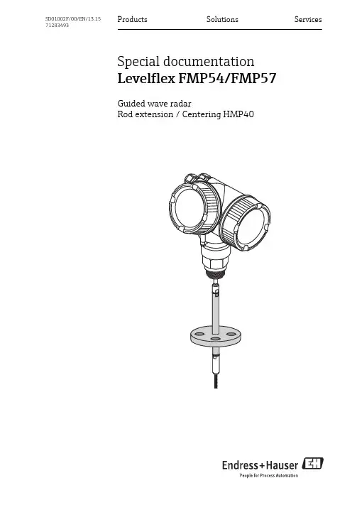
Products Solutions ServicesSpecial documentation Levelflex FMP54/FMP57Guided wave radarRod extension / Centering HMP40SD01002F/00/EN/13.1571283493Usage Levelflex FMP54/FMP572Endress+Hauser1 UsageWhen the Levelflex is installed in nozzles DN40-250 (1-1/2" - 10") with a nozzle height > 150mm/6", there is the risk of the probe touching the bottom edge of the nozzle due to material movement in the container and this can result in malfunctioning. For this reason it is necessary to use an extension rod with or without a centering disk to avoid the contact.This accessory consists of the extension rod (2) corresponding to the nozzle height (1), on which a centering disk (3) is also mounted if the nozzles are narrow orwhen working in bulk solids.A0013597When ordering Levelflex please note that the probe length minus the length of theextension rod is ordered as otherwise the rope would have to be shortened.Only use centering diks withs small diameters (DN40/DN50) if there is no significant build-up in the nozzle above the disk. The nozzle must not become clogged.2 Technical data Admissible temperature range (without center washer)no restrictionsAdmissible temperature range (with center washer)–40 to 150 °C (–40 to 302 °F) at the lower edge of the nozzle. 1)Material of extension rod 1.4404 (316L)Material of centering diskPPS GF401)There may be further restrictions depending on the process seal of the Levelflex. Please refer to the corresponding Technical Information: TI01001F (FMP54), TI01004F (FMP57).Levelflex FMP54/FMP57Ordering information Endress+Hauser 33Ordering information 3.1 Scope of delivery•1 extension rod with 2 internal threads M10x1 (with or without center disk, depending on the order)•1 setwcrew M10x1•2 sets of Nord-Lock washers •Mounting instructions (this document)Mounting Levelflex FMP54/FMP574Endress+Hauser4 MountingAWithout rod extension/centering HMP40BWith rod extension/centering HMP401Counter nut 2Rope connection 3Nord-Lock washers (two sets containing two washers each)4Extension rod (with or without center disk, depending on the order)5Setscrew M10x14.1 Required tools•1 open-end wrench SW14 (14 AF)•1 torque wrench SW14 (14 AF)Levelflex FMP54/FMP57MountingEndress+Hauser 54.2 Unmounting the rope probe 1.Open the setscrew connection between the counter nut (1) and the rope connection (2)using two wrenches (AF14).2.Unscrew the probe with the rope connection (2) from the setscrew of the device.4.3 Mounting the extension rod 1.Carefully tighten the counter nut (1) until the stop at the setscrew of the device.2.Screw the extension rod (4) with a set of Nord-Lock washers (3) into the setscrew of the device and tighten firmly using an open-end wrench and a torque wrench. The maximum torque of 15 Nm must be observed!3.Screw the setscrew (5) into the extension rod (4) until the stop.4.Use the second set of Nord-Lock washers (3) to screw down the rope connection (2) at the setscrew (5) of the extension rod and tighten the screw connection with the aid of an open-end wrench AF14 and a torque wrench. The maximuim torque of 15 Nm must be observed!4.4 If required: Shorten the rope probeInstructions for shortening the rope probe can be found in the Levelflex Operating Instructions:•FMP54: BA01001F (HART); BA01006F (PROFIBUS PA); BA01052F (FOUNDATION Fieldbus)•FMP57: BA01004F (HART); BA01009F (PROFIBUS PA); BA01055F (FOUNDATION Fieldbus)Commissioning of the Levelflex Levelflex FMP54/FMP576Endress+Hauser5Commissioning of the Levelflex 5.1 Probe length correctionAfter mounting the extension rod, an automatic or manual probe length correction must be performed. This is done with the aid of the following submenu in the operating menu of the Levelflex.Setup → Advanced setup → Probe length correctionFor details refer to the Levelflex Operating Instructions:•FMP54: BA01001F (HART); BA01006F (PROFIBUS PA); BA01052F (FOUNDATION Fieldbus)•FMP57: BA01004F (HART); BA01009F (PROFIBUS PA); BA01055F (FOUNDATION Fieldbus)5.2 SetupAfter mounting the extension rod, a new calibration of the measuring point is required in any case. This is performed by means of the Setup submenu.When doing so, it is especially important that the full distance F (Parameter Full calibration )does not range into the nozzle.For details refer to the Levelflex Operating Instructions:•FMP54: BA01001F (HART); BA01006F (PROFIBUS PA); BA01052F (FOUNDATION Fieldbus)•FMP57: BA01004F (HART); BA01009F (PROFIBUS PA); BA01055F (FOUNDATION Fieldbus)5.3 Interference echo suppression (mapping)After mounting the extension rod, a mapping curve must also be recoreded again. This is performed by the Setup → Mapping submenu. The mapping distance (Parameter Mapping end point ) must at least be the nozzle height plus 20 cm (8").5.4 Setting the upper blocking distanceThe upper blocking distance must be equal to or longer than the nozzle height. It is defined in the follwing parameter:•For level measurements:Setup → Advanced setup → Level → Blocking distance •Bei Trennschichtmessungen:Setup → Advanced setup → Interface → Blocking distance*71283493*71283493。

PMC-550A低压电动机保护控制器用户说明书(V2.6)(版权所有,翻版必究)PMC-550A用户说明书版本V2.6危险和警告本装置只能由电气专业人士进行安装,对于因不遵守本手册的说明所引起的故障,厂家将不承担任何责任。
触电、燃烧或爆炸的危险⏹装置只能由取得资格的电气工作人员才能进行安装和维护。
⏹更换装置前,应注意断开交流电压输入和装置电源,注意电流传感器的二次绕组不可短路。
⏹要用一个合适的电压检测装置来确认电压已切断。
⏹在将装置通电前,应将所有的机械部件,盖子和端子等恢复原位。
⏹装置在使用中应施加正确的电压。
不注意这些预防措施可能会引起严重伤害。
本装置设置缺省密码:0000。
本说明书版权属深圳市中电电力技术股份有限公司所有,未经书面许可,不得复制,传播或使用本说明书及其内容,违犯者将要对相关损失负责。
深圳市中电电力技术股份有限公司保留所有版权。
我们已经检查了本说明书描述硬件和软件内容的准确性。
由于不可能完全消除差错,所以我们不能保证完全正确。
本说明书将被定期升级,升级的说明书会做必要的修改,欢迎提出修改意见和建议。
说明书版本的变动恕不另行通知。
目录1装置简介 (1)1.1 概述 (1)1.2 产品特点 (1)2技术指标 (2)2.1 环境条件 (2)2.2 额定参数 (3)2.3 测量精度 (4)2.4 保护定值误差 (4)2.5 电气绝缘性能 (4)2.6 机械性能 (5)2.7 电磁兼容性能 (5)3功能介绍 (5)3.1 保护功能 (5)3.1.1 起动超时保护 (6)3.1.2 过载保护(反时限) (7)3.1.3 阻塞保护 (7)3.1.4 接地保护 (8)3.1.5 断相保护 (8)3.1.6 不平衡保护 (9)3.1.7 欠功率保护 (9)3.1.8 短路保护 (9)3.1.9 欠压保护 (10)3.1.10 过压保护 (10)3.1.11 欠载保护 (11)3.1.12 tE时间保护 (11)3.1.13 过负荷保护 (12)3.1.14 工艺联锁保护(外部故障) (12)3.1.15 温度保护 (13)3.1.16 电压断线告警 (13)3.1.17 相序保护 (14)3.1.18 合闸异常保护 (14)3.1.19 接触器保护 (14)3.1.20 紧急停车告警 (15)3.1.21 剩余电流保护 (15)3.1.22 出口配置 (15)3.2 控制功能 (15)3.2.2 上电自起动功能 (17)3.2.3 抗晃电功能 (17)3.2.4 电动机控制权限 (18)3.3 起动控制 (18)3.3.1 直接起动控制 (18)3.3.2 降压起动控制 (18)3.3.3 双向起动控制 (19)3.3.4 自动双向起动 (19)3.3.5 双速起动控制 (20)3.3.6 变频器配合起动控制 (20)3.3.7 大电机辅助起动控制 (20)3.4 可编程逻辑功能 (20)3.5 电动机运行状态监测 (21)3.6 电动机运行维护管理 (22)3.7 模拟量输出功能 (22)3.8 起动报告功能 (22)3.9 起动录波功能 (23)3.10 装置自检功能 (23)3.11 通信功能 (23)3.12 在线升级功能 (24)4操作使用 (25)4.1 按键功能说明 (25)4.2 指示灯说明 (26)4.3 菜单结构 (27)4.4 显示界面介绍 (28)4.4.1 测量数据 (29)4.4.2 DIDO状态 (29)4.4.3 参数设置 (29)4.4.4 定值清单 (34)4.4.5 事件记录 (45)4.4.6 统计信息 (46)4.4.7 装置维护 (46)4.4.8 装置信息 (48)5安装与接线 (49)5.1 整机安装 (49)5.1.1 机械尺寸图 (49)5.1.2 安装示意图 (50)5.1.4 MTA外置穿芯式电流传感器 (51)5.1.5 剩余电流互感器 (53)5.1.6 零序电流互感器 (54)5.2 装置端子说明 (55)5.2.1 装置端子图 (55)5.2.2 端子说明 (56)5.3 端子接线 (56)5.3.1 工作电源接线 (56)5.3.2 接地线连接 (56)5.3.3 电压电流温度输入接线 (56)5.3.4 开关量输入接线 (57)5.3.5 继电器输出接线 (58)5.3.6 AO输出接线 (58)5.3.7 通信接线 (58)5.4 故障分析 (59)5.5 保护控制功能使用说明 (61)5.5.1 保护控制参数设置 (61)5.5.2 过载保护动作特性速查 (61)5.5.3 电动机额定电流速查 (62)6典型接线图 (63)6.1 直接起动接线原理图 (63)6.2 星三角降压起动接线原理图 (64)6.3 自耦变压器降压起动接线原理 (65)6.4 电抗器降压起动接线原理图 (66)6.5 双向控制接线原理图 (67)6.6 双速控制接线原理图 (68)6.7 变频器配合控制接线原理图 (69)6.8 大电机辅助控制接线原理图 (70)7售后服务承诺 (71)7.1 新装置质量保证 (71)7.2 装置升级 (71)7.3 装置质保限制 (71)8手册变更记录 (71)1 装置简介1.1 概述深圳市中电电力技术股份有限公司专注于工业用户电力自动化,为满足用户对低压电动机保护、测量和控制的需求,开发出适合国内用户的PMC-550系列低压电动机保护控制器。

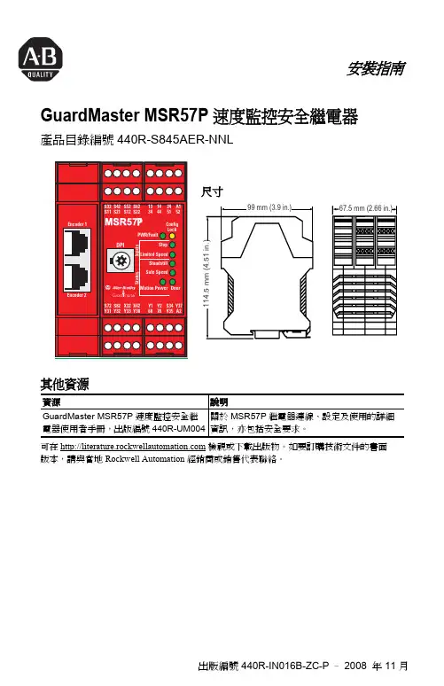
出版編號 440R-IN016B-ZC-P –2008 年 11 月安裝指南GuardMaster MSR57P 速度監控安全繼電器產品目錄編號440R-S845AER-NNL其他資源可在 檢視或下載出版物。
如要訂購技術文件的書面版本,請與當地 Rockwell Automation 經銷商或銷售代表聯絡。
資源說明GuardMaster MSR57P 速度監控安全繼電器使用者手冊,出版編號440R-UM004關於 MSR57P 繼電器連線、設定及使用的詳細資訊,亦包括安全要求。
S72X32X42S82Y31Y33Y30Y32S t 尺寸2 GuardMaster MSR57P 速度監控安全繼電器出版編號 440R-IN016B-ZC-P –2008 年 11 月其他語言安裝指引英文This instruction sheet is available in multiple languages at/literature. Select publication language and type “MSR57P” in the search field.德文Dieses Instruktionsblatt kann in mehreren Sprachen unter/literature gelesen werden. Bitte Ihre Sprache anwählen und “MSR57P” im Suchfeld eintippen.法文Ces instructions sont disponibles dans différentes langues à l’adresse suivante:/literature. Sélectionner la langue puis taper << MSR57P >> dans le champ de recherche.義大利文La presente scheda d’istruzione è disponibile in varie lingue sul sito/literature. Selezionare la lingua desiderata e digitare “MSR57P” nel campo di ricerca.西班牙文Puede encontrar esta hoja de instrucciones en varios idiomas en/literature. Seleccione el idioma de publicación y escriba “MSR57P” en el campo de búsqueda.葡萄牙文Esta folha de instruções está disponível em várias línguas em/literature. Seleccione a língua de publicação e entre com “MSR57P” no espaço de busca.波瀾文Ta kartka z instrukcjami jest dostepna w wielu jezykach na stronie:/literature. Wybierz jezyk publikacji i wpisz w polu poszukiwania “MSR57P”.捷克文Tyto pokyny jsou k dispozici v nekolika jazycích na /literature. Zvolte si jazyk publikace a do vyhledávacího polícka vepište “MSR57P”.瑞典文Detta instruktionsblad finns på olika språk på /literature. Välj önskat språk och skriv “MSR57P” i sökrutan.荷蘭文Dit instructieblad is beschikbaar in diverse talen op: /literature. Kies taal van publicatie en tik “MSR57P” in het zoekveld.繁體中文從以下網頁可以獲得本說明書的多種語言的版本:/literature 。

WTY-57微机备用电源自投装置许继电气股份有限公司目录1 装置简介⋯⋯⋯⋯⋯⋯⋯⋯⋯⋯⋯⋯⋯⋯⋯⋯⋯⋯⋯⋯⋯⋯⋯⋯⋯⋯⋯⋯⋯⋯⋯⋯⋯⋯⋯⋯⋯⋯⋯⋯⋯⋯⋯⋯⋯⋯2 2技术参数⋯⋯⋯⋯⋯⋯⋯⋯⋯⋯⋯⋯⋯⋯⋯⋯⋯⋯⋯⋯⋯⋯⋯⋯⋯⋯⋯⋯⋯⋯⋯⋯⋯⋯⋯⋯⋯⋯⋯⋯⋯⋯⋯⋯⋯⋯3 3产品硬件⋯⋯⋯⋯⋯⋯⋯⋯⋯⋯⋯⋯⋯⋯⋯⋯⋯⋯⋯⋯⋯⋯⋯⋯⋯⋯⋯⋯⋯⋯⋯⋯⋯⋯⋯⋯⋯⋯⋯⋯⋯⋯⋯⋯⋯⋯54 保护原理⋯⋯⋯⋯⋯⋯⋯⋯⋯⋯⋯⋯⋯⋯⋯⋯⋯⋯⋯⋯⋯⋯⋯⋯⋯⋯⋯⋯⋯⋯⋯⋯⋯⋯⋯⋯⋯⋯⋯⋯⋯⋯⋯⋯⋯⋯55 定值清单及动作信息说明⋯⋯⋯⋯⋯⋯⋯⋯⋯⋯⋯⋯⋯⋯⋯⋯⋯⋯⋯⋯⋯⋯⋯⋯⋯⋯⋯⋯⋯⋯⋯⋯⋯86 装置接线说明⋯⋯⋯⋯⋯⋯⋯⋯⋯⋯⋯⋯⋯⋯⋯⋯⋯⋯⋯⋯⋯⋯⋯⋯⋯⋯⋯⋯⋯⋯⋯⋯⋯⋯⋯⋯⋯⋯⋯⋯⋯⋯107 显示及键盘操作说明⋯⋯⋯⋯⋯⋯⋯⋯⋯⋯⋯⋯⋯⋯⋯⋯⋯⋯⋯⋯⋯⋯⋯⋯⋯⋯⋯⋯⋯⋯⋯⋯⋯⋯⋯⋯108 调试及异常处理说明⋯⋯⋯⋯⋯⋯⋯⋯⋯⋯⋯⋯⋯⋯⋯⋯⋯⋯⋯⋯⋯⋯⋯⋯⋯⋯⋯⋯⋯⋯⋯⋯⋯⋯⋯⋯159 投运说明及注意事项⋯⋯⋯⋯⋯⋯⋯⋯⋯⋯⋯⋯⋯⋯⋯⋯⋯⋯⋯⋯⋯⋯⋯⋯⋯⋯⋯⋯⋯⋯⋯⋯⋯⋯⋯⋯1610 贮存及保修⋯⋯⋯⋯⋯⋯⋯⋯⋯⋯⋯⋯⋯⋯⋯⋯⋯⋯⋯⋯⋯⋯⋯⋯⋯⋯⋯⋯⋯⋯⋯⋯⋯⋯⋯⋯⋯⋯⋯⋯⋯⋯⋯⋯1611 供应成套性⋯⋯⋯⋯⋯⋯⋯⋯⋯⋯⋯⋯⋯⋯⋯⋯⋯⋯⋯⋯⋯⋯⋯⋯⋯⋯⋯⋯⋯⋯⋯⋯⋯⋯⋯⋯⋯⋯⋯⋯⋯⋯⋯1612 订货须知⋯⋯⋯⋯⋯⋯⋯⋯⋯⋯⋯⋯⋯⋯⋯⋯⋯⋯⋯⋯⋯⋯⋯⋯⋯⋯⋯⋯⋯⋯⋯⋯⋯⋯⋯⋯⋯⋯⋯⋯⋯⋯⋯⋯1613 附图⋯⋯⋯⋯⋯⋯⋯⋯⋯⋯⋯⋯⋯⋯⋯⋯⋯⋯⋯⋯⋯⋯⋯⋯⋯⋯⋯⋯⋯⋯⋯⋯⋯⋯⋯⋯⋯⋯⋯⋯⋯⋯⋯⋯⋯⋯17WTY-57微机备用电源自投装置1 装置简介WTY-57系列微机备用电源自投装置(以下简称装置)是功能完善、先进的微机型备用电源自投装置,主要用于35kV及以下电压等级的进线开关和内桥开关的自投。
1.1保护功能配置:1.2 产品主要特点a. 本产品为微机保护装置,其元器件采用工业品,稳定性、可靠性高,可以在高压开关柜等恶劣的环境中工作;宽范围使用环境温度-25℃~+55℃。

环保设备触摸屏57寸说明书(doc 23页)目录产品介绍产品的型号和名称---------------------------------------------------------------------------------------------1产品用途、适用范围及特点-------------------------------------------------------------------------------1主要技术性能和技术参产品使用条件--------------------------------------------------------------------------------------------------2主要技术参数----------------------------------------------------------------------------------------------------3产品的功能和特点---------------------------------------------------------------------------------------------3主要结构和工作原理产品结构-----------------------------------------------------------------------------------------------------------5主回路工作原理-----------------------------------------------------------------------------------------------5安装与使用设备的验收试验-----------------------------------------------------------------------------------------------6设备的安装------------------------------------------------------------------------------------------------------6设备的使用------------------------------------------------------------------------------------------------------7设备的维护、保养--------------------------------------------------------------------------------------------------12产品的成套性和备件-----------------------------------------------------------------------------------------------12附录---------------------------------------------------------------------------------------------------------------------------13▲化学工业:用于回收烟气中有价值的成份,在制酸工业中用于除雾、除尘等。
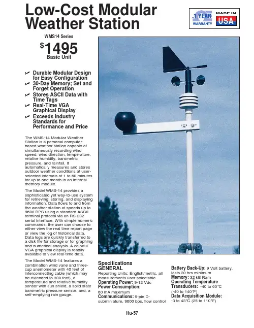
Hu-57Low-Cost Modular Weather StationSpecifications GENERALReporting Units: English/metric, all measurements user selectable Operating Power:9-12 Vdc Power Consumption:60 mA maximumCommunications:9-pin D-subminiature, 9600 bps, flow controlBattery Back-Up:9 Volt battery,lasts 30 hrs minimum Memory:32 kB Ram Operating Temperature Transducers:-40 to 60°C (-40 to 140°F)Data Acquisition Module:-3 to 43°C (25 to 110°F)The WMS-14 Modular Weather Station is a personal computer-based weather station capable of simultaneously recording windspeed, wind direction, temperature,relative humidity, barometric pressure, and rainfall. Itautomatically measures and stores outdoor weather conditions at user-selected intervals of 1 to 60 minutes for up to one month in an internal memory module.The Model WMS-14 provides asophisticated yet way-to-use system for retrieving, storing, and displaying information. Data flows to and from the weather station at speeds up to 9600 BPS using a standard ASCII terminal protocol via an RS-232serial interface. With simple numeric commands, the user can choose to either view the real time report page or view the log of historical data.Data logs are quickly transferred to a disk file for storage or for graphing and numerical analysis. A colorful VGA graphical display is readily available to view real-time data.The Model WMS-14 features a combination wind vane and three-cup anemometer with 40 feet of interconnecting cable (which may be extended to 300 feet), atemperature and relative humidity sensor with sun shield, a solid state barometric pressure sensor, and, a self-emptying rain gauge.ߜDurable Modular Designfor Easy Configuration ߜ30-Day Memory; Set andForget OperationߜStores ASCII Data withTime TagsߜReal-Time VGAGraphical Display ߜExceeds IndustryStandards forPerformance and PriceUSAMADE INWMS14 Series$1495Basic UnitHu-58HuTo Order (Specify Model No.)Model No.Price DescriptionWMS-14$1495Complete weather station with tripod mastWMS-14EPA 1735Complete weather station with high sensitivity windsensor.WMS-14D 495Data Acquisition moduleWMS-05D 450High sensitivity wind/speed direction sensorWMS-14TH 250Outdoor temperature/humidity sensor, with 25' cable WMS-14THS 90Solar radiation shield for temp/RH sensor WMS-14BP 200Barometric PressureWMS-14RF 125Rainfall collector, 25' cable WMS-14TM90Tripod mast 10'WMS-14 comes complete with outdoor temperature/humidity sensor with 25' cable, barometric pressure sensor, solar radiation shield, rain collector plus 25' cable, 10' tripod mast, data acquisition module, plus complete operator's manual.Ordering Example: WMS-14 weather station with mast ($1495) plus WMS-EC-40extension cable ($40), $1495 + 40 = $1535.AccessoriesModel No.Price Description WMS-EC-40$2040' Extension cable for wind sensor WMS-RGC-402040' Extension cable for rain sensor WMS-TC-402440' Extension cable for temperature humidity sensorWMS-14 Data Acquisition Module IncludedWINDSpeed Range:0-99.9 mph (0-160 kph)Resolution:0.1 mph Accuracy:±3% for sustained 2 sec avg.Time Constant:2 secDIRECTIONResolution:22°(16 compass points)Time Constant:2 secTEMPERATURERange:-40 to +140°F Resolution:1°F Accuracy:±2°F Update Rate:1 min. avg.Wind Chill Enable Range:-40 to +7°C (-40 to +45°F)BAROMETRIC PRESSURERange:28.25 to 30.75 in Hg Resolution:±0.01 in Hg or ±1 millibarAbsolute Accuracy:±0.05 in Hg Update Rate:1/minAltitude Offset:-0 to 10,000 feet,screwdriver adjustableHYDROMETERRange:0-100% RHAccuracy:±3% mid range, ±6% @20% & 90% RHTime Constant:5 min. avg.RAIN GAGEResolution:0.004"/0.01"/1 mmm Accuracy:5%Max. Rate:3in/hrTIMEKEEPINGFormat:4 digit, 24 hr military timeAccuracy:5 sec in 24 hrs.CANADA www.omega.ca Laval(Quebec) 1-800-TC-OMEGA UNITED KINGDOM www. Manchester, England0800-488-488GERMANY www.omega.deDeckenpfronn, Germany************FRANCEwww.omega.fr Guyancourt, France088-466-342BENELUX www.omega.nl Amstelveen, NL 0800-099-33-44UNITED STATES 1-800-TC-OMEGA Stamford, CT.CZECH REPUBLIC www.omegaeng.cz Karviná, Czech Republic596-311-899TemperatureCalibrators, Connectors, General Test and MeasurementInstruments, Glass Bulb Thermometers, Handheld Instruments for Temperature Measurement, Ice Point References,Indicating Labels, Crayons, Cements and Lacquers, Infrared Temperature Measurement Instruments, Recorders Relative Humidity Measurement Instruments, RTD Probes, Elements and Assemblies, Temperature & Process Meters, Timers and Counters, Temperature and Process Controllers and Power Switching Devices, Thermistor Elements, Probes andAssemblies,Thermocouples Thermowells and Head and Well Assemblies, Transmitters, WirePressure, Strain and ForceDisplacement Transducers, Dynamic Measurement Force Sensors, Instrumentation for Pressure and Strain Measurements, Load Cells, Pressure Gauges, PressureReference Section, Pressure Switches, Pressure Transducers, Proximity Transducers, Regulators,Strain Gages, Torque Transducers, ValvespH and ConductivityConductivity Instrumentation, Dissolved OxygenHeatersBand Heaters, Cartridge Heaters, Circulation Heaters, Comfort Heaters, Controllers, Meters and SwitchingDevices, Flexible Heaters, General Test and Measurement Instruments, Heater Hook-up Wire, Heating Cable Flow and LevelAir Velocity Indicators, Doppler Flowmeters, LevelMeasurement, Magnetic Flowmeters, Mass Flowmeters,Pitot Tubes, Pumps, Rotameters, Turbine and Paddle Wheel Flowmeters, Ultrasonic Flowmeters, Valves, Variable Area Flowmeters, Vortex Shedding FlowmetersData AcquisitionAuto-Dialers and Alarm Monitoring Systems, Communication Products and Converters, Data Acquisition and Analysis Software, Data LoggersPlug-in Cards, Signal Conditioners, USB, RS232, RS485 and Parallel Port Data Acquisition Systems, Wireless Transmitters and Receivers。
XA00643F-A/00/B2/01.1171158144Safety InstructionsLevelflexFMP54/56/57PROFIBUS PAZone 20/21DIP A20/21 T A , T* IP66en -Document: XA00643F-ASafety instructions for electrical apparatus for explosion-hazardous areas Èä3zh -文档:XA00643F-A爆炸环境中电气仪表的安全指南Èä9Levelflex FMP54/56/57XA00643F-A 2Endress+HauserXA00643F-A Levelflex FMP54/56/57LevelflexFMP54/56/57PROFIBUS PATable of ContentsAssociated documentation . . . . . . . . . . . . . . . . . . . . . . . . . . . . . . . . . . . . . . . . . . . . . . . . 4Supplementary documentation . . . . . . . . . . . . . . . . . . . . . . . . . . . . . . . . . . . . . . . . . . . . . 4Manufacturer's certificates . . . . . . . . . . . . . . . . . . . . . . . . . . . . . . . . . . . . . . . . . . . . . . . . 4Extended order code . . . . . . . . . . . . . . . . . . . . . . . . . . . . . . . . . . . . . . . . . . . . . . . . . . . . 4Safety instructions: General . . . . . . . . . . . . . . . . . . . . . . . . . . . . . . . . . . . . . . . . . . . . . . . 6Safety instructions: Special conditions . . . . . . . . . . . . . . . . . . . . . . . . . . . . . . . . . . . . . . . . 6Safety instructions: Installation . . . . . . . . . . . . . . . . . . . . . . . . . . . . . . . . . . . . . . . . . . . . . 6Temperature tables . . . . . . . . . . . . . . . . . . . . . . . . . . . . . . . . . . . . . . . . . . . . . . . . . . . . . 7Connection data . . . . . . . . . . . . . . . . . . . . . . . . . . . . . . . . . . . . . . . . . . . . . . . . . . . . . . . 7 Endress+Hauser3Levelflex FMP54/56/57XA00643F-A4Endress+HauserAssociated documentation This document is an integral part of the following Operating Instructions:BA01006F/00 (FMP54), BA01009F/00 (FMP56/57)The Operating Instructions pertaining to the device apply.Supplementary documentation Explosion-protection brochure:CP021Z/00The Explosion-protection brochure is available:•In the download area of the Endress+Hauser website: → Download → Advanced → Documentation Code: CP021Z•On the CD for devices with CD-based documentationManufacturer's certificates NEPSI Declaration of Conformity Certificate number:GYJ11.1553XAffixing the certificate number certifies conformity with the standards:•GB3836.1-2010•GB12476.1-2000•GB12476.4-2010, with the following standard under :-IEC61241-0:2004Extended order codeThe extended order code is indicated on the nameplate, which is affixed to the device in such a way that it is clearly visible. Additional information about the nameplate is provided in the associated Operating Instructions.Structure of the extended order code •Basic specificationsThe features that are absolutely essential for the device (mandatory features) are specified in the basic specifications. The number of positions depends on the number of features available. The selected option of a feature can consist of several positions.•Optional specificationsThe optional specifications describe additional features for the device (optional features). The number of positions depends on the number of features available.The features have a 2-digit structure to aid identification (e.g. JA). The first digit (ID) stands for the feature group and consists of a number or a letter (e.g. J = test, certificate).The second digit constitutes the value that stands for the feature within the group (e.g. A = 3.1 material (wetted parts), inspection certificate).More detailed information about the device is provided in the following tables. These tables describe the individual positions and IDs in the extended order code which are relevant to hazardous locations.FMP5x-*************+A*B*C*D*E*F*G*..------------------------------------------------------------------------Device typeBasic specificationsOptional specifications* =PlaceholderAt this position, an option (number or letter) selected from the specification is displayed instead of the placeholders.XA00643F-A Levelflex FMP54/56/57Endress+Hauser 5Device type: FMP54, FMP56, FMP57Basic specificationsOptional specificationsPosition Selected option Description1, 2ApprovalNF Zone 20/21DIP A20/21 T A , T* IP663Power Supply; Output G 2-wire, PROFIBUS PA4Display; Operation A C Without LCD, via communicationLCD SD02, push button + data backup function 5HousingB CDual compartment, 316L (GT18)Dual compartment, Alu coated (GT20)9, 10SealAB (only FMP56)A4 (only FMP57)B3 (only FMP56/57)D1 (only FMP54)D2 (only FMP54)Viton,–30...120 °C Viton,–30...150 °C EPDM, –40...120 °CGraphite, –196...280 °C (XT)Graphite, –196...450 °C (HT)ID Selected option DescriptionMxProbe DesignMBME (only FMP54)Sensor remote, 3 m/9 ft cable, detachable + mounting bracketCoax ground tube multiple punchedLevelflex FMP54/56/57XA00643F-A6Endress+HauserSafety instructions:General•Staff must meet the following conditions for mounting, electrical installation, commissioning and maintenance of the device:-Be suitably qualified for their role and the tasks they perform -Be trained in explosion protection -Be familiar with national regulations•For installation, use and maintenance of the device, users must also observe the requirements stated in the Operating Instructions and the standards:-GB50257-1996: "Code for construction and acceptance of electric device for explosion atmospheres and fire hazard electrical equipment installation engineering".-GB15577-2007: "Safety regulations for dust explosive prevention and protection".-GB12476.2-2006: "Electrical apparatus for use in the presence of combustible dust,Part 1-2: Electrical apparatus protected by enclosures and surface temperature limitation - Selection, installation and maintenance".•Install the device according to the manufacturer's instructions and national regulations.•Do not operate the device outside the specified electrical, thermal and mechanical parameters.•Only use the device in media to which the wetted materials have sufficient durability.•Refer to the temperature tables for the relationship between the permitted ambient temperature for the sensor and/or transmitter, depending on the range of application, and the temperature class.•Modifications to the device can affect the explosion protection and must be carried out by staff authorized to perform such work by Endress+Hauser.•When replacing the probe electronics or opening the connection between the remote cable and the probe, a jumper plug must be used or a short-circuit must be established between the probe contact and the potential equalization conductor to avoid electrostatically charging the probe.•After mounting and connecting the probe, ingress protection of the housing must be at least IP66. Perform the following to achieve the degree of protection: - Screw the cover tight.-Mount the cable entry correctly.Safety instructions:Special conditions Permitted ambient temperature range at the electronics housing: –40 °C ≤ T a ≤ +80 °C.Observe the information in the temperature tables.Safety instructions:Installationå 1A Zone 211Tank; Zone 20, Zone 212Electronics compartment Ex iaD; Electronic insert 3Connection compartment DIP A214Power supply5Potential equalization line 6Potential equalizationXA00643F-A Levelflex FMP54/56/57Endress+Hauser 7•In the case of process connections made of polymeric material or with polymeric coatings, avoid electrostatic charging of the plastic surfaces.•After aligning (rotating) the housing, retighten the fixing screw (see Operating Instructions).•When mounting the device:-Exclude any mechanical damage or friction during the application. -Pay particular attention to flow conditions and tank fittings.•Continuous service temperature of the connecting cable: –40 to ≥ +85 °C; in accordance with the range of service temperature taking into account additional influences of the process conditions (T a,min and T a,max +20 K).•In the event of additional or alternative special varnishing on the housing or other metal parts: -Observe the danger of electrostatic charging and discharge. -Do not rub surfaces with a dry cloth.•Only use certified cable entries or sealing plugs.The metal sealing plugs supplied meet this requirement.•Before operation:-Screw in the cover all the way.-Tighten the securing clamp on the cover.Intrinsic safety•The device can be connected to the Endress+Hauser FXA291 service tool: refer to the Operating Instructions.Temperature tables Èä15Connection dataBasic specification, Position 1, 2 (Approval) = NF Connection compartment DIP A21Electronics compartment Ex i Service interface (CDI)Taking the following values into consideration, the device can be connected to the Endress+Hauser FXA291 service tool or a similar interface:Basic specification, Position 3 (Power Supply; Output) = G TRC [07]Terminal 1 (+), 2 (–)Terminal 3 (+), 4 (–)Power supply:Output PFS:U N = 32 V DC I max = 25 mA U m = 250 V ACU N = 35 V DC I n = 70 mA U m = 250 V ACService interface U i = 7.3 Veffective inner inductance L i = negligible effective inner capacitance C i = negligible U o = 7.3 V I o = 100 mA P o = 160 mWpermitted outer inductance L o = negligible permitted outer capacitance C o = negligibleLevelflex FMP54/56/57XA00643F-A 8Endress+HauserXA00643F-A Levelflex FMP54/56/57LevelflexFMP54/56/57PROFIBUS PA目录相关资料 . . . . . . . . . . . . . . . . . . . . . . . . . . . . . . . . . . . . . . . . . . . . . . . . . . . . . . . . . . . . 10辅助文档 . . . . . . . . . . . . . . . . . . . . . . . . . . . . . . . . . . . . . . . . . . . . . . . . . . . . . . . . . . . . 10制造商证书 . . . . . . . . . . . . . . . . . . . . . . . . . . . . . . . . . . . . . . . . . . . . . . . . . . . . . . . . . . 10扩展订货号 . . . . . . . . . . . . . . . . . . . . . . . . . . . . . . . . . . . . . . . . . . . . . . . . . . . . . . . . . . 10安全指南:概述 . . . . . . . . . . . . . . . . . . . . . . . . . . . . . . . . . . . . . . . . . . . . . . . . . . . . . . 12安全指南:特殊条件 . . . . . . . . . . . . . . . . . . . . . . . . . . . . . . . . . . . . . . . . . . . . . . . . . . . 12安全指南:安装 . . . . . . . . . . . . . . . . . . . . . . . . . . . . . . . . . . . . . . . . . . . . . . . . . . . . . . 12温度表 . . . . . . . . . . . . . . . . . . . . . . . . . . . . . . . . . . . . . . . . . . . . . . . . . . . . . . . . . . . . . . 13连接数据 . . . . . . . . . . . . . . . . . . . . . . . . . . . . . . . . . . . . . . . . . . . . . . . . . . . . . . . . . . . . 13 Endress+Hauser9Levelflex FMP54/56/57XA00643F-A相关资料本文档是下列操作手册的组成部分:BA01006F/00 (FMP54), BA01009F/00 (FMP56/57)应遵守设备的操作手册。
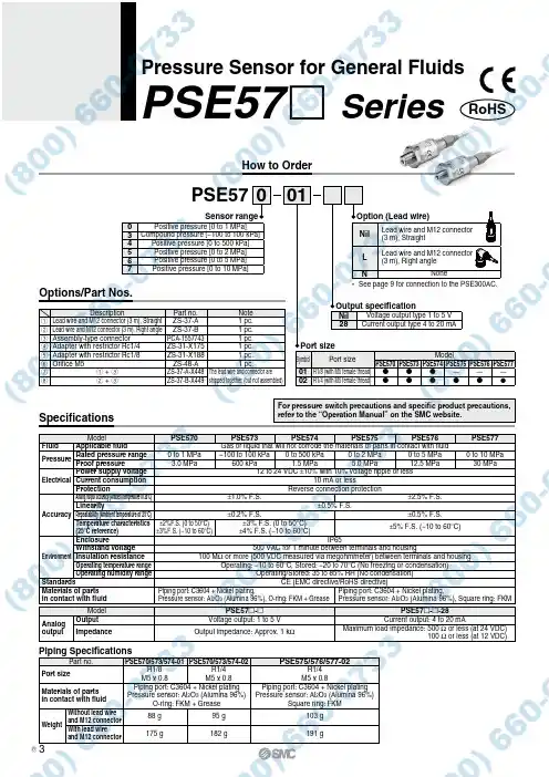
For pressure switch precautions and specific product precautions, refer to the “Operation Manual” on the SMC website.RoHSPSE57 SeriesPressure Sensor for General FluidsHow to OrderPSE57001Port sizeSensor rangeOutput specificationSpecificationsOptions/Part Nos.Model PSE570PSE573PSE574PSE575PSE576PSE577FluidApplicable fluid Gas or liquid that will not corrode the materials of parts in contact with fluid PressureRated pressure range 0 to 1 MPa −100 to 100 kPa 0 to 500 kPa 0 to 2 MPa 0 to 5 MPa 0 to 10 MPaProof pressure 3.0 MPa 600 kPa 1.5 MPa 5.0 MPa 12.5 MPa 30 MPa Electrical Power supply voltage 12 to 24 VDC ±10% with 10% voltage ripple or lessCurrent consumption10 mA or less Protection Reverse connection protection Accuracy Analog output accuracy (Ambient temperature of 25°C)±1.0% F.S.±2.5% F.S.Linearity ±0.5% F.S.Repeatability (Ambient temperature of 25°C)±0.2% F.S.±0.5% F.S.Temperature characteristics (25°C reference)±2%F.S. (0 to 50°C)±3%F.S. (−10 to 60°C)±3% F.S. (0 to 50°C)±4% F.S. (−10 to 60°C)±5% F.S. (−10 to 60°C)Environment Enclosure IP65Withstand voltage 500 VAC for 1 minute between terminals and housingInsulation resistance100 M Ω or more (500 VDC measured via megohmmeter) between terminals and housing Operating temperature range Operating: −10 to 60°C, Stored: −20 to 70°C (No freezing or condensation)Operating humidity range Operating/Stored: 35 to 85% RH (No condensation)Standards CE (EMC directive/RoHS directive)Materials of parts in contact with fluidPiping port: C3604 + Nickel plating,Pressure sensor: Al 2O 3 (Alumina 96%), O-ring: FKM + Grease Piping port: C3604 + Nickel plating,Pressure sensor: Al 2O 3 (Alumina 96%), Square ring: FKM ModelPSE57 -PSE57 - -28Analog outputOutput Voltage output: 1 to 5 V Current output: 4 to 20 mAImpedanceOutput impedance: Approx. 1 k ΩMaximum load impedance: 500 Ω or less (at 24 VDC)100 Ω or less (at 12 VDC)Nil Voltage output type 1 to 5 V 28Current output type 4 to 20 mASymbolPort sizeModelPSE570PSE573PSE574PSE575PSE576PSE57701R1/8 (with M5 female thread) ———02R1/4 (with M5 female thread)0Positive pressure [0 to 1 MPa]3Compound pressure [−100 to 100 kPa]4Positive pressure [0 to 500 kPa]5Positive pressure [0 to 2 MPa]6Positive pressure [0 to 5 MPa]7Positive pressure [0 to 10 MPa]Piping SpecificationsPart no.PSE570/573/574-01PSE570/573/574-02PSE575/576/577-02Port sizeR1/8M5 x 0.8R1/4M5 x 0.8R1/4M5 x 0.8Materials of parts in contact with fluid Piping port: C3604 + Nickel plating Pressure sensor: Al 2O 3 (Alumina 96%)O-ring: FKM + GreasePiping port: C3604 + Nickel plating Pressure sensor: Al 2O 3 (Alumina 96%)Square ring: FKMWeightWithout lead wire and M12 connector88 g 95 g 103 g With lead wireand M12 connector175 g182 g191 gOption (Lead wire)Nil Lead wire and M12 connector (3 m), StraightL Lead wire and M12 connector (3 m), Right angleNNone* See page 9 for connection to the PSE300AC.DescriptionPart no.Note q Lead wire and M12 connector (3 m), Straight ZS-37-A 1 pc.w Lead wire and M12 connector (3 m), Right angle ZS-37-B 1 pc.e Assembly-type connector PCA-1557743 1 pc.r Adapter with restrictor Rc1/4ZS-31-X175 1 pc.t Adapter with restrictor Rc1/8ZS-31-X188 1 pc.y Orifice M5ZS-48-A 1 pc.u q + e ZS-37-A-X448The lead wire and connector are shipped together. (but not assembled)iw + eZS-37-B-X4493B。


Release Note Guardmaster MSR57P Speed Monitoring Safety Relay Catalog Number 440R-S845AER-NNL About This PublicationThis document explains how to install new firmware into the MSR57P safety relay. These release notes correspond to revision 1.005 of the MSR57P firmware.Before You Begin The procedure assumes that you have Drive Explorer software,version 5.02.07 or later, installed on your PC and you havesuccessfully connected to the MSR57P relay.Topic Page About This Publication 1Before You Begin 1Corrected Anomalies 3Update Firmware 3Confirm the Update 6Download Your Saved Configuration File 6Additional Resources 7TIP If you do not have DriveExplorer software, you candownload the free version, DriveExplorer Lite, at /drives/driveexplorer/free_download.html.Indicator DriveExplorer Software DriveExplorer Software2 Guardmaster MSR57P Speed Monitoring Safety RelayDownload the Firmware Update FileFollow these steps to obtain the firmware upgrade file.1.Go to /support/firmware.htmland choose Minotaur Safety Relays.2.Click the file named MSR57_1_005_Update.msi.3.Save the file to your hard drive.Save Your MSR57P Configuration to Your PCThe Firmware update process deletes the configuration and restoresthe default parameters. If you save your configuration to your PC, youcan reload it following the update.unch DriveExplorer software and connect to the relay.2.In the tree view, expand the MSR57P relay.3.Expand the Parameter groups and select the Security group.4.Place the relay in Run mode by setting the P6 [Operating Mode]parameter to 1.5.Record the value of the P10 [Signature ID] parameter.You will need to verify this value is unchanged after you reloadyour configuration following the update.6.From the Actions menu, choose Upload and Save to save yourconfiguration.7.Browse to the directory where you want to save your file. the file and click Save.This is the current configuration of the MSR57P relay. Once thefirmware update is complete, you can download thisconfiguration back into the relay.Publication 440R-RN001A-EN-P - April 2009Publication 440R-RN001A-EN-P - April 2009Guardmaster MSR57P Speed Monitoring Safety Relay 3Corrected AnomaliesThe anomalies corrected in this firmware revision update are listed in this table.Update Firmware Follow these steps to update the firmware of the MSR57P relay.1.Open Drive Explorer software.2.Click Connect to connect to the MSR57P relay.AnomalyDescriptionFollowing an input fault, reset into actively monitoring motionwas allowed without firstrequiring that both input channelsbe cycled to OFF (open) to confirmthe fault has been cleared.This anomaly affected the Door Monitor input (DM_In), Enabling Switch Monitor input (ESM_In), Lock Monitor input (LM_In), and Safe Limited Speed input (SLS_In) when they are configured for 2NC 3s, 1NC + 1NO 3s, or 2 OSSD 3s.If inputs listed are configured in any of the above configurations and an input fault is detected, the anomaly did not require that both relay input channels turn OFF (open) before a reset into activelymonitoring motion is permitted. For example, if an input was configured as 2NC 3s and only one of thechannels turned OFF (opened), the relay would detect the fault and perform the required stop function.You should be required to open both channels on that input for a successful reset command.Corrected firmware requires that both input channels be cycled to OFF (open) before a reset intoactively monitoring motion is permitted.Dual Feedback Speed fault occurs when safety mode is Disabled. A Dual Feedback Speed fault results when an error is detected between the speed from the first encoder and the speed from the second encoder. This fault should not occur in Disabled mode,because speed monitoring is not in effect.The Safe Stop input (SS_In) wasnot required to be cycled after aHIM stop request.If you press the stop button on a HIM connected to the DPI port, a stop request is initiated. The requirement to cycle the SS_In before attempting a safe stop reset was not enforced when the system was in the safe state with no faults present. Corrected firmware enforces this requirement inall cases.If you press the stop button on the HIM, you must press the green Start button on the HIM and thencycle the SS_In before requesting a reset of the MSR57P relay. Otherwise, the reset will not besuccessful.4 Guardmaster MSR57P Speed Monitoring Safety Relay3.Select the MSR57P relay and click the information icon to open the relay Properties dialog box.4.Select the Details tab to view the revision levels currentlyinstalled on your MSR57P relay.5.Click Flash Update.6.Click Browse.Publication 440R-RN001A-EN-P - April 2009Guardmaster MSR57P Speed Monitoring Safety Relay 5 7.Find the directory where you installed the files and select thatdirectory.8.Select 1.005 and click Next.9.On the Confirm Flash Update dialog box, click FLASH to startthe update.It takes approximately 7…10 minutes to update the relay. TheExecuting Flash Update dialog box tracks the progress of theupdate.10.When the update is complete, click Close.11.Click Yes when Drive Explorer software requests to reconnect tothe MSR57P relay.Publication 440R-RN001A-EN-P - April 20096 Guardmaster MSR57P Speed Monitoring Safety RelayConfirm the Update Follow these steps to confirm that the update was successful.1.Select the MSR57P relay and click the information icon to open the relay Properties dialog box.2.Click the Details tab and verify that these revisions are shown.3.Close the MSR57P dialog box.Download Your Saved Configuration File Follow these steps to reload your configuration to the relay.1.In the DriveExplorer tree view, expand the MSR57P relay.2.From the Actions menu, choose Download Saved File.3.Click Yes to acknowledge that setup values may change.4.Browse to the configuration file you saved before performingthe firmware update (*.csf file).5.Select your file and click Open.6.Expand the Parameters and choose the Security group.pare the value of [P10] Signature ID to the value yourecorded before the upgrade.The two values should be the same.8.Place the relay in Run mode by setting the P6 [Operating Mode]parameter to 1.File Revision ChecksumApplication Program 1.005.010xC081Boot Program 1.005.010x7104Core Boot A 1.003.010xB049Core Executive A 1.005.010xE2E8Core Boot B 1.003.010xE9A3Core Executive B 1.005.010xF578After you verify that the Signature ID values match, you mustrevalidate your application, following the guidelines in theGuardmaster MSR57P Speed Monitoring Safety Relay User Manual,publication 440R-UM004A-EN-P.Publication 440R-RN001A-EN-P - April 2009Guardmaster MSR57P Speed Monitoring Safety Relay 7Additional Resources For information on installing, configuring, and operating an MSR57Prelay, including safety requirements, refer to the Guardmaster MSR57PSpeed Monitoring Safety Relay User Manual, publication440R-UM004A-EN-P.You can view or download publications at:. To order paper copies oftechnical documentation, contact your local Rockwell Automationdistributor or sales representative.Publication 440R-RN001A-EN-P - April 2009Publication 440R-RN001A-EN-P - April 2009 Copyright © 2009 Rockwell Automation, Inc. All rights reserved. Printed in the U.S.A.Rockwell Automation SupportRockwell Automation provides technical information on the Web to assist you in using its products. At , you can find technical manuals, a knowledge base of FAQs, technical and application notes, sample code and links to software service packs, and a MySupport feature that you can customize to make the best use of these tools.For an additional level of technical phone support for installation, configuration, and troubleshooting, we offer TechConnect support programs. For more information, contact your local distributor or Rockwell Automation representative, or visit .Installation AssistanceIf you experience a problem within the first 24 hours of installation, please review the information that's contained in this manual. You can also contact a special Customer Support number for initial help in getting your product up and running.New Product Satisfaction ReturnRockwell Automation tests all of its products to ensure that they are fully operational when shipped from the manufacturing facility. However, if your product is not functioning and needs to be returned, follow these procedures.Allen-Bradley, Rockwell Automation, Guardmaster, and DriveExplorer are trademarks ofRockwell Automation, Inc.Trademarks not belonging to Rockwell Automation are property of their respective companies.United States1.440.646.3434 Monday – Friday, 8 a.m. – 5 p.m. EST Outside United States Please contact your local Rockwell Automation representative for any technical support issues.United StatesContact your distributor. You must provide a Customer Support case number (call the phone number above to obtain one) to your distributor in order to complete the return process.Outside United StatesPlease contact your local Rockwell Automation representative for the return procedure.。
instruction for useThank you for selecting an AVK product. With correct use, it will give long and reliable service. This manual has been prepared to assist you install, operate and maintain the valve to the maximum efficiency. For ease ofreference, it has been divided into sections covering all aspects of use, and it is in the users best interests to read it and ensure that it is fully understood.1. introductionAVK series 57 gate valves are available in DN50 to DN400. The valve has a full and straight bore corresponding to the nominal diameter and can be installed independent of the flow direction. To keep the advantage of the full and straight bore vertical installation is recommended, however, flow/pressure limitations outlined below should be observed.The valves are 100% factory tested hydrostatically.The valves can be applied in various end connections to suit application needs. See datasheets.it iS important to StatE opErating tEmpEraturE, prESSurE, mEdium and opErating conditionS WitH EnQuiriES/ordErS, So tHE moSt SuitaBlE valvE Will BE SuppliEd For Your SpEciFic purpoSE. materials:castings (gland flange, body, bonnet & stem cap)DuctileIron, 500-7 to AS 1831coatingFusion bonded epoxy (FBE)Stem, gland flange boltsStainless SteelWedgeDuctile Iron, with EPDM rubberBonnet boltsDN50-250PN16 Grade 8.8, PN25 Grade 12.9, sealed with hot meltDN300-400PN16 and PN25 Grade 12.9, sealed with hot meltRefer to individual datasheets for specific information2. installation• When installing the gate valves, ensure that the seats and the flange faces are clean.• When valves are provided with lifting lugs, plates or eye nuts, these must be used to lift the valve.• To ensure adequate sealing it is important to select the correct type of gasket for the medium concerned, gaskets with the correct flange size must be used.• Place valve between pipe flanges, and insert the bolts.• Tighten bolts loosely.• Tighten bolts in a diagonal sequence to ensure flanges are pulled parallel.• Finally tighten bolts to correct torque levels as recommended in WSA 109.2.1. Bolts2.1.1 Bolt sizeThe following table shows bolt size you should use for which valve dimensions.aS 2129 aS 2129table B5 table E table Fdn BoltsQ uantity BoltsQ uantityQ uantity Bolts50 M16 4 M16 4 M16 480 M16 4 M16 4 M16 8100 M16 4 M16 8 M16 8150 M16 8 M20 8 M20 12200 M16 8 M20 8 M20 12M16 8 - - - -225250 M16 8 M20 12 M24 12300 M20 12 M24 12 M24 16375 M24 12 M24 12 M27 16400 M24 12 M24 12 M27 20SERIES: 57/90 57/98 57/55 57/65 57/75SERIES: 57/40 57/42 57/43 57/48 57/50 57/60 57/70SERIES: 55/74 55/344. maintenance4.1. generalThe valve is designed for underground use with minimum maintenance and requires no lubrication.In the event of a spares replacement becoming necessary the recommended procedure is as follows:4.2 replacement of Stem SealsThis can be carried out with valve under pressure in the pipeline, but take care over step ‘a’ to ensure a seal is formed between wedge and bonnet.a) Fully open valve to ensure it is back-seated.b) In the case of a stem cap being fitted carefully prise out plastic insert (21). Remove stem cap bolt (20) and stem cap (19).c) Remove 2 hexagon headed bolts (17) on top of gland flange (13).d) Gland flange (13) can now be lifted clear of stem (5) allowing access to the stem sealing arrangement. Lift clear of stem andreplace the 2 ‘O’ Rings (16). Refit bushing (14) on stem taking care not to nip or tear the new ‘O’ Rings.e) Refit gland flange (13) with a new gland flange ‘O’ Ring (12) and tighten the 2 hexagon headed bolts (17) using a torquewrench set at 35 Nm.f) Refit stem cap assembly i.e. (19) (20) (21).g) Close wedge by a few turns and check the integrity of the new seal arrangement.4.3 replacement of Wedgea) Isolate valve and ensure there is no pressure in the pipeline.b) Adjust handwheel or stem cap to put the wedge into a slightly open position.c) Remove hot melt/screw cover (9) to expose bonnet bolts (6) then remove bolts.d) Lift the entire bonnet assembly (8) and wedge (3) clear of valve body (1).e) Unscrew wedge (3) from the stem (5).f) Fit new wedge by reversing step ‘e’, take care that the wedge is in a mid-position on the stem so that when refitting it willbe clear of the base and body.g) Replace bonnet gasket (7). It is suggested that the bonnet bolts (6) are inserted into the bonnet holes first and then thegasket (7) is fitted over them. The whole bonnet assembly can now be refitted onto the body (1).h) Tighten the bonnet bolts (6) following a diagonal sequence and using a torque wrench set at 25 Nm to 30 Nm. Re-set thetorque wrench at 40 Nm to 50 Nm and re-tighten the bolts following a circumferential sequence.i) Check integrity of seal by re-charging the main.j) Should any leakage be found, tighten bonnet bolts (6) following the diagonal sequence as in h) with the torque wrench set at 75 Nm for stainless steel bolts, 60 Nm for Grade 8.8 and 12.9 bolts.k) We recommend that the bonnet bolt heads are re-sealed to prevent corrosion. Ensure the sealant is water resistant by using, for example, a silicone type sealant.4.4 replacement of Stem Seal ‘o’ ring (item 10)a) isolate valve and ensure there is no pressure in the pipeline.b) Turn keyed stem to put the wedge into a slightly open position.c) In the case of a stem cap being fitted carefully prise out plastic insert (21).Remove stem cap bolt (20) and stem cap (19).d) Remove 2 hexagon bolts (17) on top of gland flange (13).e) The gland flange (13) can now be lifted clear of stem (5) allowing access to the stem seal arrangement.f) Fully close the valve in order to raise the stem (5) clear of the bonnet (8) ensuring that the two stem collars (11) are retainedfor re-assembly.g) Remove stem seal ‘O’ ring (12) and replace with a new ‘O’ ring (12), grease the ‘O’ ring with Water Regulations approvedgrease e.g. Rocol Aqua-Silh) Replace the two ‘O’ rings (16) and nylon bushing (14) in the glandflange (13). Grease internally using the approved grease.Grease thrust collar grooves in stem (5). Screw stem (5) back into wedge (3) whilst fitting stem collars (11) ensuring they seat fully inside recess in bonnet (8).i) Refit gland flange (13) with a new gland flange ‘O’ ring (12) and tighten the 2 hexagon bolts (17) using a torque wrench setat 35 Nm.j) Refit stem cap (19), bolt (20) and insert (21).k) Close wedge by a few turns and check the integrity of the new seal arrangementl) The check the integrity of the new seal arrangement, it will be necessary to re-charge the main slowly and open and close the wedge (3) a few times.notE: It is vitally important to ensure all air is vented prior to full charging the main.。
APV H OM Rannie® 57T / Gaulin® 57TAPV ® Rannie and Gaulin 57T HomogenizerThe more modular and flexible design of the APV 57T makes it suitable for a wide range of applications in dairy, food, beverage, industrial and pharmaceutical industries. Homogenizing valves can easily be changed to accommodate different types of product and/or capacities on the same homogenizer.Liquid End options include the Rannie three-piece valve housing and the Gaulin mono-block design, both available with a choice of valves, plungers and packings according to your requirements.Design features of Rannie, Gaulin and the new Power End simplify routine maintenance with emphasis on reliability and sturdiness in order to reduce total costs of ownership.The APV ® 57T homogenizer is a three-plunger reciprocating pump, fitted with hydraulically actuated homogenising valves.The APV 57T incorporates a durable slow-Balanced low speed crankshaft for reduced noiseN EW AN D I M PR OVE D OPE RATI N G B E N E FITS Optimal Operator Interface • All controls placed logically together• Gauges and other visual indicators are visible from the operating position • Direct view of key power end check points through a window • Modular electrical controlsHigh reliability• Internal gear transmission• Enhanced oil treatment and cooling system with oil filter as standard • Low centre of gravity for reduced vibrationMaintenance friendly design• Easy access for servicing, reduced maintenance time • Low machine height for ergonomic access • Visual service indicators• Improved cooling and oil treatment indicators • Access to electric control box from the outside • Built-in belt tensionerRannie Three-Piece Valve Housing ArrayGaulin Mono-Block Valve HousingSPX FLOW, Inc. reserves the right to incorporate our latest design and material changes without notice or obligation.Design features, materials of construction and dimensional data, and certifications as described in this bulletin, are provided for your information only and should not be relied upon unless confirmed in writing. Please contact your local sales representative for product availability in your region. For more information visit .The green “” and “” are trademarks of SPX FLOW, Inc.APV_Homogeniser-57T_3176_BRO_USVersion: 03/2020COPYRIGHT © 2020 SPX FLOW, Inc.Identification Number: APV-3176-USAM E R I CAS S PX FLOW611 Sugar Creek Road Delavan, WI 53115USA+1 262 728 1900APAC S PX FLOW7F, No. 1568, Huashan Road Shanghai, 200052China+86 21 2208 5888E M EA S PX FLOWOestmarken 7, 2860 Soeborg Denmark +45 70 278 222Based in Charlotte, North Carolina, SPX FLOW, Inc. (NYSE: FLOW) is a multi-industry manufacturing leader. For more information, please visit D I ME N S I O N S LE N GT H I N / M M W I DTH I N / M M H E I G HT I N / M M W E I G HT (I N CL. M OTOR)LB S. / KGSTAN DAR D M AC H I N E 89 / 2,260 56.5 / 1,43556 / 1,4255,725 / 2,600PAC K E D I N C RATE 118 / 3,000 71 / 1,80071 / 1,8006,600 / 3,000STA N DAR D I N C L. LOW N O I SE E XTE N SI O N111 / 2,82064 / 1,63066 / 1,6806,850 / 3,100C U B I C M EASU R E O F STAN DARD C RATI N G: 9.72 M3。
PostScript..............................................................................................NIV guidelinesWe congratulate the British Thoracic Society (BTS)Standards of Care Committee on their excellent guidelines on non-invasive ventila-tion(NIV)in acute respiratory failure.1The guidelines are timely in that many district general hospitals(DGH)are setting up an NIV service.If our DGH experience is typical, others may be surprised how quickly NIV takes off.Our DGH serves a catchment area of about200000people and use of NIV has increased from51patients in the year1998/9 to227in2000/1.Whereas in1998/978%of all the NIV treated patients were on the intensive care unit(ICU),in2000/171%were treated on wards.The keen involvement of the ICU anaesthetists has been pivotal in setting up the service.We would query the statement that all patients started on NIV should be transferred to the care of a respiratory physician as soon as possible.In2000/165patients were treated on the ICU with NIV,many of these surgical patients being weaned off ventilators.Simi-larly,28“surgical”patients were treated on the wards with NIV.Should chest physicians really have to take over hospital care of all these patients?The guidelines do not address the issue of the use of NIV in palliation of breathlessness. In acute exacerbations of chronic obstructive pulmonary disease(COPD)breathlessness settles more rapidly with NIV than with con-ventional treatment.2In patients with severe respiratory distress who refused endotracheal intubation,anecdotally NIV was effective in reducing breathlessness.3It is not surprising that the role of NIV in treating breathlessness is unclear,given the uncertainty over the effi-cacy of other interventions which have been available for many years such as oxygen,ben-zodiazepines,morphine,or breathing exer-cises.We have found NIV useful in reducing dyspnoea in some patients with end stagerespiratory disease,and agree with the guide-lines that it is vital it be clearly documentedwhether NIV is being used with palliative orcurative intent,and whether or not to proceedto invasive ventilation.C D Shee,M GreenQueen Mary’s Hospital,Sidcup,Kent DA146LT,UKReferences1British Thoracic Society Standards of CareCommittee.Non-invasive ventilation in acuterespiratory failure.Thorax2002;57:192–211.2Plant PK,Owen JL,Elliott MW.Early use ofnon-invasive ventilation for acuteexacerbations of chronic obstructivepulmonary disease on general respiratorywards:a multi-centre randomised controlledncet2000;355:1931–5.3Meduri GU,Fox RC,Abou-Shala N,et al.Non-invasive mechanical ventilation via facemask in patients with acute respiratory failurewho refused endotracheal intubation.CritCare Med1994;22:1584–90.We read the BTS guideline on non-invasiveventilation(NIV)in acute respiratory failure1with great interest.The paper is an excellentsummary and a very good reference for anumber of situations related to this novelapproach.We have,however,some questionswhich we wish to raise.Nowadays it is widely accepted that NIV issuperior to both invasive mechanical ventila-tion and standard medical treatment inselected patients with exacerbations of hyper-capnic chronic obstructive pulmonary disease(COPD).The skills required for NIV are easilylearnt and the equipment required is rela-tively inexpensive.The complication rate isvery low compared with invasive ventilation,and it has been shown by Plant et al2that NIVis cheaper with a lower mortality rate thanstandard medical treatment in patients withCOPD.The use of NIV outside the ICU and byphysicians,nurses,or respiratory care practi-tioners is also beneficial,allowing early inter-vention to prevent further respiratory deterio-ration,access to respiratory support forpatients who would not otherwise be admit-ted to the ICU,and the provision of support ina less intimidating setting.Success rates ofNIV in such patients can be higher than90%,3depending on appropriate selection ofpatients,close monitoring in thefirst4–6hours,and the experience of the staff.However,according to the BTS guideline,1NIVdoes not appear to be a suitable treatmentmodality for low income countries because ofthe limited availability of ICU facilities.Although there is no doubt that the bestsettings in which to use NIV are those statedin the guideline,it is not always possible for alow income country to set up a countrywideICU service.The number of patients withacute COPD exacerbations is no lower than indeveloped countries,so shouldn’t we use NIVin selected COPD patients with acute exacer-bations even if there is no ICU service in thenear area?Would it be ethical not to use thissimple and inexpensive device in thoseselected patients if you have a well trainedstaff but no ICU service?O Dikensoy,A Filiz,E EkinciDepartment of Pulmonary Diseases,GaziantepUniversity,School of Medicine,Gaziantep27070,Turkey;******************References1British Thoracic Society Standards of CareCommittee.Non-invasive ventilation in acuterespiratory failure.Thorax2002;57:192–211.2Plant PK,Owen JL,Elliott MW.Early use ofnon-invasive ventilation for acuteexacerbations of chronic obstructivepulmonary disease on general respiratorywards:a multicentre randomised controlledncet2000;355:1931–5.3Kramer N,Meyer TJ,Meharg J,et al.Randomized prospective trial of noninvasivepositive pressure ventilation in acuterespiratory failure.Am J Respir Crit Care Med1995;151:1799–806.Author’s replyIn response to the criticism that it is unneces-sary to transfer all patients on non-invasiveventilation(NIV)to the care of a respiratoryphysician as soon as possible,these are guide-lines not rules.I am unhappy with thesuggestion that NIV should be managed bysurgeons,although clearly there may behospitals where the surgeons have sufficienttraining and experience in NIV for this to beacceptable.I agree that NIV can be used topalliate breathlessness,but I did not specifi-cally address this area of use in the guideline.In answer to the question as to whether itwould be ethical to use NIV if there is nointensive care service available,I agree that inspecial circumstances this would be entirelyreasonable.W J M KinnearDepartment of Respiratory Medicine,Queen’sMedical Centre,Nottingham NG72UH,UK;*****************************GM-CSF therapy in pulmonaryalveolar proteinosisIn the letter by M G de V ega et al entitled“GM-CSF therapy in pulmonary alveolar pro-teinosis”which appeared on page837of theSeptember issue of Thorax(V olume57,No9),the name of Dr A Romero was inadvertentlyomitted as thefirst author.The authors of theletter should have been:A Romero,M G deV ega,A Sánchez-Palencia,A Ramírez andS Cervera.The publishers apologise for thiserror.If you have a burning desire to respond to a paper published in Thorax,why not make use of our“rapid response”option? Log on to our website (),find th1e paper that interests you,and send your response via email by clicking on the“eLetters”option in the box at the top right hand corner.Providing it isn’t libellous or obscene,it will be posted within seven days.You can retrieve it by clicking on“read eLetters”on our homepage.The editors will decide as before whether to also publish it in a future paper issue.Thorax2002;57:10021002 on December 24, 2023 by guest. Protected by copyright./ Thorax: first published as 10.1136/thorax.57.11.1002-a on 1 November 2002. Downloaded from。
第一部分:音箱模拟器什么是音箱模拟器,有什么用?输入CD信号到吉他音箱的line in,无论多高档的吉他音箱都不会得到很好的效果,说明吉他专用音箱并不在乎音染,有时甚至为了得到个性鲜明的吉他音色故意做一些非常lo-fi的设计。
吉他音箱本身的失真音色在不同的音量下差异很大,不是单独增益gain、drive或者master就能得到满意的效果,有时候即使你不需要很大的音量,但是仍然不得不为了音色开大吉他音箱音量。
同一个吉他音箱,无论在它之前使用任何效果器,最终的音色仍会有它自身鲜明的特性。
对于需要音色比较单一的吉他手来说,几个单块加上一个不错的吉他音箱就完全能玩的很爽。
但是大多数时候我们都不能用或者不需要非常大的音量,或者需要多种不同特性的音箱音色,或者受制于器材与房间特性即使有好的吉他音箱也没办法得到比较好的录音质量,这时候选择一个音箱模拟器就比较合适。
传统的数字合成效果器或者单块效果器默认的信号输出强度一般都是对应吉他音箱的吉他信号输入而设计。
数字合成效果器一般都有简单的音箱模拟功能,也可以选择不同的输出接口(例如AX1000g)或者模式(例如ZOOM 707)对应使用吉他音箱或者普通扩音系统的场合,因此它们同样可以不用吉他音箱而获得正确的信号匹配,但是由于它们设计上并不偏重模拟真实吉他音箱的声学特性,所以最终能得到怎样的音色还是要与吉他音箱共同决定。
音箱模拟器的电路原理与数字合成效果器相同,但是设计上偏重于完全模拟用吉他音箱得到的最终音色,也就是绕过吉他音箱直接得到效果器+吉他音箱的音色。
音箱模拟器可以赋予一个音染不很重的吉他音箱其他经典音箱的音色,但是主要还是用来用家用音响、耳机等普通放音设备得到吉他音箱的音色或者直接为录音设备提供具有音箱质感的声源。
普通音箱能否得到吉他音箱特有的音色?如果你对音色优劣的标准来自唱片等介质,那么道理上普通扩音系统绝对能满足你的需要。
道理很简单,你用任何一个扩音系统(耳机、多媒体音箱等)听唱片,觉得里面的音色不错,那就说明这个扩音系统具有回放那种音色的能力,也就是说通过一些设备你一定能用它们再现这种音色。