IMO防火控制图(A.952(23))
- 格式:doc
- 大小:450.50 KB
- 文档页数:11
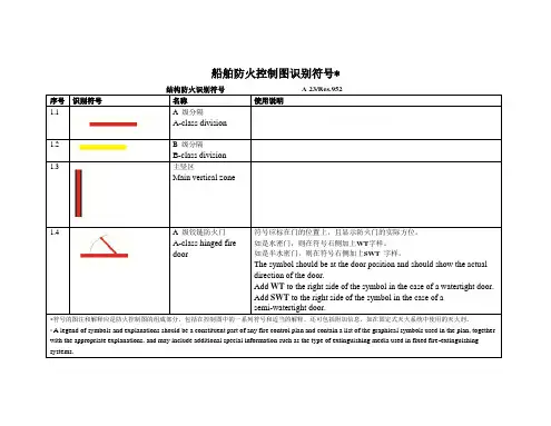
船舶防火控制图识别符号*序号识别符号名称使用说明1.1 A 级分隔A-class division1.2 B 级分隔B-class division1.3 主竖区Main vertical zone1.4 A 级铰链防火门A-class hinged firedoor 符号应标在门的位置上,且显示防火门的实际方位。
如是水密门,则在符号右侧加上WT字样。
如是半水密门,则在符号右侧加上SWT 字样。
The symbol should be at the door position and should show the actual direction of the door.Add WT to the right side of the symbol in the case of a watertight door. Add SWT to the right side of the symbol in the case of asemi-watertight door.符号的图注和解释应是防火控制图的组成部分,包括在控制图中的一系列符号和适当的解释,还可包括附加信息,如在固定式灭火系统中使用的灭火剂。
* A legend of symbols and explanations should be a constituent part of any fire control plan and contain a list of the graphical symbols used in the plan, together with the appropriate explanations, and may include additional special information such as the type of extinguishing media used in fixed fire-extinguishing systems.1.5 B 级铰链防火门B-class hinged firedoor 符号应标在门的位置上,且显示防火门的实际方位。


I M O防火控制图A文件管理序列号:[K8UY-K9IO69-O6M243-OL889-F88688]M S C77/26/A d d.1附件14大会决议草案船舶防火控制图识别符号大会忆及国际海事组织公约第15(j)条有关本大会在海上安全规则和导则方面的职能,牢记1974年国际海上人命安全条约修正案第II-2/15.2.4条规定,要求船上应有固定展示的防火控制图作为对船上高级船员的指导,和一套防火控制图或具有该图的小册子的复制品,永久性地置于甲板室外面有醒目标示的风雨密盒子里,以有助于岸上的消防人员。
认识到国际识别符号的使用将极大地增加船舶防火控制图对船员和岸上消防人员的实用性,还认识到A.654(16)决议关于船舶防火控制图识别符号的规定,注意到ISO在与IMO的密切合作下,制定了ISO17631:2002船舶和航海技术标准——船舶消防图、救生设备和脱险通道,提供了总体上符合A.654(16)决议中规定的相应识别符号的防火识别符号,尤其注意到MSC/Cir.1050通函请成员国政府将ISO17631:2002标准提起与制定或应用船舶防火控制图有关的船舶制造者、船东、船舶运营者、船长和岸上消防人员以及其他有关各方的注意,使他们能在自愿基础上在制定或应用SOLAS公约第II-2/15.2.4条规则要求的船舶防火控制图过程中应用这一标准,这使A.654(16)决议的修订工作非常迫切,审议了海上安全委员会在其77届会议上提出的建议案,1.通过船舶防火控制图识别符号,其文本附于本决议的附件中;2.敦促成员国政府将上述识别符号提起与制定或应用船舶防火控制图有关的船舶制造者、船东、船舶运营者、船长和岸上消防人员以及其他有关各方的注意,以鼓励在2004年1月1日或之后建造的船舶上应用SOLAS公约第II-2/15.2.4条规则要求的船舶防火控制图;3.请成员国政府将ISO17631:2002标准提起船舶制造者、船东、船舶运营者和船长的注意,以便他们在制定船舶防火控制图时应用上述标准中的附加指导;4.同意于2004年1月1日之前建造的船舶可继续配备应用A.654(16)决议中所列识别符号的防火控制图;5.要求海上安全委员会保持对本决议的审议并在必要时进行调整。
前 言2010年,新造入级船完工交付1000万总吨成为中国船级社发展史上的一个新里程碑。
面对2011年超千万吨的新造船检验任务,继续做好新造入级船舶检验工作,避免在以后船舶营运期间被港口国检验官(PSCO)检查出因建造检验带来的缺陷或由此可能导致的船舶滞留,维护CCS入级船舶在TOKYO MOU、PARIS MOU、USCG 等港口国控制组织以及国际船级社协会(IACS)中的声誉,确保CCS级新造船在日后正常营运,显得尤为重要。
为此,编者收集、汇编了近一年来新造船检验期间以及新造船投入营运后发现的较典型建造检验缺陷,对其作了加工、提炼、完善、归纳、整理,力求明确缺陷所依据的公约或规范的章节,并配以相应的图片使问题简化易懂,希望能对全社建造检验验船师提供帮助、学习、借鉴,以期尽最大努力使新造船不带“病”出厂,不断提高检验质量。
不足之处,还敬请予以斧正。
建造入级处2011年3月编 写 委 员 会 名 单主编:王学忠、刘林评审:杨琪、姜波涛、余玮、俞士国、杨志勇、钱文强目 录1. 消防、救生方面的缺陷 ………………………………………3-272. 防污染、航行安全和信号设备方面的缺陷 …………………28-32 3.载重线及69国际吨位公约方面的缺陷………………………33-414. 船体方面的缺陷 ………………………………………………42-705. 轮机及电气方面的缺陷 ………………………………………71-881. 消防、救生方面的缺陷1.1 防火门安装(门框与舱壁之间) 无法保证相应的防火分隔等级、耐火完整性,不满足SOLAS公约第II-2/9条有关要求(应按不低于耐火型式试验批准的安装方式或其它等效安装方式进行安装,确保防火门框与舱壁之间部分与舱壁具有相同的的耐火完整性)。
见图1.1-1至图1.1-5。
图1.1-1 图1.1-2图1.1-3 图1.1-4图1.1-51.2 穿过具有防火等级要求舱壁的电缆贯穿件没有按要求封堵或电缆的穿管系数大于0.4或电缆管口没有打磨(会损伤电缆),不满足SOLAS公约第II-2/9条有关要求及我社“钢质海船入级规范”(以下简称“钢规”)第4篇第2章第12节有关要求。
绘制防火控制图应注意的事项周社宁【摘要】防火控制图是船舶航行中海事部门对船舶进行监管和船舶火灾中能否有效施救的重要依据.本文就船舶设计或完工资料提供单位如何正确绘制和送审防火控制图提出了应注意的事项,对顺利通过防火控制图的审查有一定的提示作用.【期刊名称】《江苏船舶》【年(卷),期】2011(028)002【总页数】2页(P26-27)【关键词】船舶;防火控制图;注意事项【作者】周社宁【作者单位】江苏省船舶检验局,江苏,南京,210004【正文语种】中文【中图分类】U692.7防火控制图是船舶的重要文件资料之一,是船舶航行中海事机构对船舶进行安全监管和船舶火灾中能否有效施救的重要依据。
在工作中发现部分国内航行船舶的设计、建造单位在送审图纸和完工资料中对防火控制图相关要求的理解和绘制常出现一些误差,因此船舶防火控制图的正确绘制及有关要求的完整表达是很重要的。
1 提供防火控制图的目的防火控制图的目的旨在使所有船员、船上工作人员、乘客、施救人员在船舶发生火警时,能根据该图的规定标识内容,采取正确有效的措施,从而减少船上人员的伤害和船舶设施的损失。
因此船舶设计或完工资料提供单位应对提供该图的意义和目的予以重视,认真和正确地完成该图的绘制与送审。
2 要求配置防火控制图的船舶根据现行船舶法定检验技术规则及其修改通报规定,国内航行下列船舶必须配置防火控制图:(1)海船:所有客船以及 500总t及以上的货船和液货船,均应设有防火控制图。
其他船舶可设有消防设备布置图。
(2)内河船:Ⅰ型、Ⅱ型客滚船,船长50 m以上的客船(包括车客渡船、餐饮趸船),2 000总t及以上的货船及滚装货船,500总 t及以上的油船均应设有防火控制图。
其他船舶可设有消防设备布置图。
根据《内河船舶法定检验技术规则》第 1篇的定义及相关法规、规范,这里所指的油船是指装运闪点小于或大于60℃散装油类的船舶及散装化学品船、液化气体船等。
3 防火控制图引用标准及相关图纸3.1 引用标准(1)GB/T 3894.6-1984“船舶布置图图形符号救生设备”。

船舶防火控制图识别符号*结构防火识别符号 A 23/Res.952序号识别符号名称使用说明1.1 A 级分隔A-class division1.2 B 级分隔B-class division1.3 主竖区Main vertical zone1.4 A 级铰链防火门A-class hinged firedoor 符号应标在门的位置上,且显示防火门的实际方位。
如是水密门,则在符号右侧加上WT字样。
如是半水密门,则在符号右侧加上SWT 字样。
The symbol should be at the door position and should show the actual direction of the door.Add WT to the right side of the symbol in the case of a watertight door. Add SWT to the right side of the symbol in the case of asemi-watertight door.符号的图注和解释应是防火控制图的组成部分,包括在控制图中的一系列符号和适当的解释,还可包括附加信息,如在固定式灭火系统中使用的灭火剂。
* A legend of symbols and explanations should be a constituent part of any fire control plan and contain a list of the graphical symbols used in the plan, together with the appropriate explanations, and may include additional special information such as the type of extinguishing media used in fixed fire-extinguishing systems.1.5 B 级铰链防火门B-class hinged firedoor 符号应标在门的位置上,且显示防火门的实际方位。
For reasons of economy, this document is printed in a limited number. Delegates are kindly asked to bring their copies to meetings and not to request additional copies.INTERNATIONAL MARITIME ORGANIZATIONIMOEASSEMBLY 23rd session Agenda item 17A 23/Res.952 25 February 2004Original: ENGLISHResolution A.952(23)Adopted on 5 December 2003(Agenda item 17)GRAPHICAL SYMBOLS FOR SHIPBOARD FIRE CONTROL PLANSTHE ASSEMBLY,RECALLING Article 15(i) of the Convention on the International Maritime Organization concerning the functions of the Assembly in relation to regulations and guidelines concerning maritime safety,BEARING IN MIND that regulation II-2/15.2.4 of the International Convention for the Safety of Life at Sea (SOLAS), 1974, as amended, requires that fire control plans be permanently exhibited for the guidance of the ship’s officers and that a duplicate set of fire control plans or a booklet containing such plans be permanently stored in a prominently marked weathertight enclosure outside the deckhouse for the assistance of shore-side fire-fighting personnel,RECOGNIZING that the use of international symbols for shipboard fire control plans would greatly increase their usefulness, both for the crew of the ship and for shore-based fire brigades,RECALLING ALSO resolution A.654(16) on Graphical symbols for fire control plans,NOTING that ISO had, in close co-operation with IMO, developed standard ISO 17631:2002 – Ships and marine technology – Shipboard plans for fire protection, life-saving appliances and means of escape, providing fire protection symbols which generally conform to the corresponding symbols set out in resolution A.654(16),NOTING IN PARTICULAR that, through MSC/Circ.1050, Member Governments had been invited to bring standard ISO 17631:2002 to the attention of shipbuilders, shipowners, shipoperators, shipmasters, shore-based fire-fighting personnel and other parties concerned with the preparation or use of shipboard fire control plans, so that they might use it, on a voluntary basis, for the preparation or use of the shipboard fire control plans required by SOLAS regulation II-2/15.2.4, pending the outcome of the work related to the revision of resolution A.654(16),A 23/Res.952 - 2 -HAVING CONSIDERED the recommendation made by the Maritime Safety Committee at its seventy-seventh session,1. ADOPTS the Graphical symbols for shipboard fire control plans, set out in the Annex to the present resolution;2. URGES Governments to bring the aforementioned graphical symbols to the attention of shipbuilders, shipowners, shipoperators, shipmasters, shore-based fire-fighting personnel and other parties concerned with the preparation or use of shipboard fire control plans with a view to encouraging their use for the preparation of the shipboard fire control plans required by SOLAS regulation II-2/15.2.4, for ships constructed on or after 1 January 2004;3. INVITES Governments to bring standard ISO 17631:2002 to the attention of shipbuilders, shipowners, shipoperators and shipmasters so that they may use the additional guidance contained therein for the preparation of shipboard fire control plans;4. AGREES that ships constructed before 1 January 2004 may continue to carry fire control plans that use the graphical symbols contained in resolution A.654(16);5. REQUESTS the Maritime Safety Committee to keep this resolution under review and to amend it as necessary.- 3 - A 23/Res.952ANNEXGRAPHICAL SYMBOLS FOR SHIPBOARD FIRE CONTROL PLANS * Graphical symbols for structural fire protectionNo. Graphical symbol Reference Comments on use1.1A-class division 1.2B-class division1.3Main vertical zone1.4A-class hingedfire doorThe symbol should be at the door position and should show the actual direction of the door. Add WT to the right side of the symbol in the case of a watertight door. Add SWT to the right side of the symbol in the case of a semi-watertight door.1.5B-class hinged fire door The symbol should be at the door position and should show the actual direction of the door. Add WT to the right side of the symbol in the case of a watertight door.Add SWT to the right side of the symbol in the case of a semi-watertight door.*A legend of symbols and explanations should be a constituent part of any fire control plan and contain a list of the graphical symbols used in the plan, together with the appropriate explanations, and may include additional special information such as the type of extinguishing media used in fixed fire-extinguishing systems.A 23/Res.952 - 4 -No. Graphical symbol ReferenceComments on use1.6A-class hinged self-closing fire door The symbol should be at the door position and should show the actual direction of the door. Add WT to the right side of the symbol in the case of a watertight door.Add SWT to the right side of the symbol in the case of a semi-watertight door.1.7B-class hinged self-closing fire door The symbol should be at the door position and should show the actual direction of the door. Add WT to the right side of the symbol in the case of a watertight door.Add SWT to the right side of the symbol in the case of a semi-watertight door.1.8A-class sliding fire door The symbol should be at the door position and should show the actual direction of the door.Add WT to the right side of the symbol in the case of a watertight door.Add SWT to the right side of the symbol in the case of a semi-watertight door.1.9B-class sliding fire door The symbol should be at the door position and should show the actual direction of the door.Add WT to the right side of the symbol in the case of a watertight door.Add SWT to the right side of the symbol in the case of a semi-watertight door.- 5 -A 23/Res.952No. Graphical symbolReferenceComments on use1.10A-class self-closing sliding fire doorThe symbol should be at the door position and should show the actual direction of the door.Add WT to the right side of the symbol in the case of a watertight door.Add SWT to the right side of the symbol in the case of a semi-watertight door.1.11B-class self-closing sliding fire door The symbol should be at the door position and should show the actual direction of the door.Add WT to the right side of the symbol in the case of a watertight door.Add SWT to the right side of the symbol in the case of a semi-watertight door.1.12Ventilation remote control or shut-off Colour of the circle and a letter at the right side of the symbol should indicate as follows: A = blue for accommodation and service spaces;M = green for machinery spaces;C = yellow for cargo spaces.1.13Remote control for skylight1.14Remote control for watertight doors or fire doorsAdd WT to the right side of the symbol to indicate remote control for watertight doors or FD to indicate remote control for fire doors.A 23/Res.952 - 6 -No. Graphical symbolReferenceComments on use1.15Fire damperColour of the circle and a letter at the right side of the symbol should indicate as follows:A = blue for accommodation and servicespaces;M = green for machinery spaces;C = yellow for cargo spaces.Identification number of the damper may be shown at the bottom of the symbol.1.16Closing device for ventilation inlet or outletColour of the circle and a letter at the right side of the symbol should indicate as follows:A = blue for accommodation and servicespaces;M = green for machinery spaces;C = yellow for cargo spaces.Identification number of the closing device may be shown at the bottom of the symbol.1.17Remote controlfor fire damper(s)Colour of the circle and a letter at the right side of the symbol should indicate as follows:A = blue for accommodation and servicespaces;M = green for machinery spaces;C = yellow for cargo spaces.Identification number of the damper may be shown.- 7 -A 23/Res.952No. Graphical symbolReferenceComments on use1.18Remote control for closing device(s) for ventilation inlet and outletColour of the circle and a letter at the right side of the symbol should indicate as follows:A = blue for accommodation and servicespaces;M= green for machinery spaces;C = yellow for cargo spaces.Identification number of the closingdevice(s) may be shown.Graphical symbols for fire-protection appliancesNo. Graphical symbolReferenceComments on use2.1Fire protection appliances or structural fire protection plan2.2Remote control for fire pump(s) 2.3Fire pump(s)The type, quantity of water delivered per time unit, and pressure head should be indicated either at the right side of the symbol or in the legend.2.4Remote control for emergency fire pump or fire pump suppliedby the emergency source of power 2.5Emergency firepumpThe type, quantity of water delivered per time unit, and pressure head should be indicated either at the right side of the symbol or in the legend.A 23/Res.952 - 8 -No. Graphical symbol ReferenceComments on use2.6Fuel pump(s) remote shut-off2.7Lube oil pump(s) remote shut-off2.8Remote control for bilge pump(s)2.9Remote control for emergency bilge pump2.10Remote control for fuel oil valves2.11Remote control for lube oil valves2.12Remote control for fire pump valve(s)2.13Remote releasestationIndicate at the bottom of the symbol the protected space. Extinguishing media should be colour coded in the lower part of the symbol and be indicated by a letter at the right side of the symbol as follows: grey – CO 2 for carbon dioxide or N for nitrogen, brown – H for gas other than CO 2 or N (type of gas to be indicated), white – P for powder, green – W for water.- 9 - A 23/Res.952No. Graphical symbolReferenceComments on use2.14International shore connection2.15Fire hydrant2.16Fire main section valveIndicate the reference number of the valveat the right side of the symbol. 2.17Sprinkler sectionvalveIndicate the reference number of the valve at the right side of the symbol.This symbol may also be applied to equivalent water-extinguishing systems.Valves for automatic dry-pipe sprinkler systems should be indicated in the legend. 2.18Powder sectionvalveIndicate the reference number of the valve at the right side of the symbol.2.19Foam sectionvalveIndicate the reference number of the valve at the right side of the symbol.2.20Fixed fire-extinguishing installationExtinguishing media should be colour-coded in the centre part of the symbol and indicated by a letter on top of the symbol as follows: grey – CO 2 for carbon dioxide or N for nitrogen, yellow – F for foam, brown – H for gas other than CO 2 or N (type of gas to be indicated), white – P for powder, green – W for water.A 23/Res.952 - 10 -No. Graphical symbol ReferenceComments on use2.21Fixed fire-extinguishing batteryExtinguishing media should be colour-coded in the lower part of the symbol and indicated by a letter on top of the symbol as follows: grey – CO 2 for carbon dioxide or N for nitrogen, yellow – F for foam, brown – H for gas other than CO 2 or N (type of gas to be indicated), white – P for powder, green – W for water.2.22Fixed fire-extinguishing bottle, placed in protected area Extinguishing media should be colour-coded in the centre part of the symbol and indicated by a letter on top of the symbol as follows: grey – CO 2 for carbon dioxide or N for nitrogen, yellow – F for foam,brown – H for gas other than CO 2 or N (type of gas to be indicated), white – P for powder, green – W for water.2.23High expansion foam supplytrunk (outlet)Indicate at the bottom of the symbol the protected space, if necessary.2.24Water spray system valvesIndicate at the bottom of the symbol the protected space, if necessary.2.25Inert gas installation2.26MonitorExtinguishing media should be colour-coded in the centre part of the symbol and indicated by a letter on the right side of the symbol as follows: yellow – F for foam, white – P for powder, green – W for water. 2.27Fire hose and nozzleIndicate the hose length at the right side of the symbol; where only one type of hose is used, the information can be shown in the legend. Extinguishing media should be colour-coded in the lower part of the symbol and indicated by a letter on the right side of the symbol as follows: yellow – F for foam, white – P for powder, green – W for water.- 11 - A 23/Res.952No. Graphical symbolReferenceComments on use2.28Fire extinguisherIndicate type of extinguishing media (CO 2 for carbon dioxide, F for foam, H for gas other than CO 2 (type of gas to be indicated), P for powder, W for water) and capacity (kg for gas and powder, litres for water and foam) at the right side of the symbol. Media should be colour-coded in the lower part of the symbol as follows: grey for carbon dioxide, yellow for foam, brown for gas other than CO 2, white for powder, green for water.2.29Wheeled fire extinguisherIndicate type of extinguishing media (CO 2 for carbon dioxide, F for foam, H for gas other than CO 2 (type of gas to be indicated), P for powder, W for water) and capacity (kg for gas and powder, litres for water and foam) at the right side of the symbol. Media should be colour-coded in the centre part of the symbol as follows: grey for carbon dioxide, yellow for foam, brown for gas other than CO 2, white for powder, green for water. 2.30Portable foam applicator unit or relevant spare tank(s)2.31Fire lockerIndicate the number of the fire locker at the right side of the symbol. The principal contents of each fire locker should be indicated in the legend.2.32Space or group of spaces protected by fire-extinguishing systemIndicate type of extinguishing media (CO 2 for carbon dioxide, F for foam, H for gas other than CO 2 (type of gas to be indicated), P for powder, W for water, S for sprinkler or high pressure water extinguishing system) and capacity (kg for gas and powder, litres for water and foam) at the top of the symbol. Add suffix “L” for fixed local application fire fighting system. Media should be colour-coded in the symbol as follows: grey for carbon dioxide, yellow for foam, brown for gas other than CO 2, white for powder, green for water, orange for sprinkler or high pressure water extinguishing system.A 23/Res.952 - 12 -No. Graphical symbol ReferenceComments on use2.33Water fog applicator2.34Emergency source of electrical power (generator) 2.35Emergency source of electrical power (battery)2.36Emergency switchboard2.37Air compressor for breathing devices2.38Control panel for fire detection and alarm system2.39Pushbutton/switch for general alarm2.40Manually operated callpointThe use of this symbol is optional at the discretion of the competent authority.- 13 - A 23/Res.952No. Graphical symbolReferenceComments on use2.41Space or group of spaces monitored by smoke detector(s)The space(s) should be identified.2.42Space or groupof spaces monitored by heat detector(s)The space(s) should be identified.2.43Space or group of spaces monitored by flame detector(s)The space(s) should be identified. 2.44Space monitoredby gas detector(s)Graphical symbols for means of escape and escape-related devices3.1Primary escaperoute3.2Secondary escape route3.3Emergency escape breathing device (EEBD)Indicate the quantity of the EEBDs stowed at the right side of the symbol.__________。
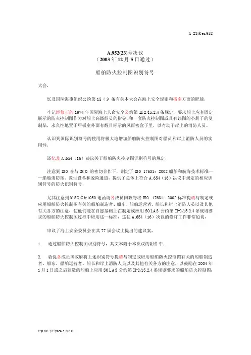
A.952(23)号决议(2003年12月5日通过)船舶防火控制图识别符号大会,忆及国际海事组织公约第15(j)条有关本大会在海上安全规则和指南方面的职能,牢记经修正的1974年国际海上人命安全公约第II-2/15.2.4条规定,要求船上应有固定展示的防火控制图作为对船上高级船员的指导,和一套防火控制图或具有该图的小册子的复制品,永久性地置于甲板室外面有醒目标示的风雨密盒子里,以有助于岸上的消防人员。
认识到国际识别符号的使用将极大地增加船舶防火控制图对船员和岸上消防人员的实用性,还忆及A.654(16)决议关于船舶防火控制图识别符号的规定,注意到ISO在与IMO的密切合作下,制定了ISO 17631:2002船舶和航海技术标准——船舶消防图、救生设备和脱险通道,提供了总体上符合A.654(16)决议中规定的相应识别符号的防火识别符号,尤其注意到MSC/Cir.1050通函请各成员国政府将ISO 17631:2002标准提请与制定或应用船舶防火控制图有关的船舶制造者、船东、船舶运营者、船长和岸上消防人员以及其他有关各方的注意,使他们能在自愿基础上在制定或应用SOLAS公约第II-2/15.2.4条规则要求的船舶防火控制图过程中应用这一标准,这使A.654(16)决议的修订工作非常迫切,审议了海上安全委员会在其77届会议上提出的建议案,1.通过船舶防火控制图识别符号,其文本附于本决议的附件中;2.敦促各成员国政府将上述识别符号提请与制定或应用船舶防火控制图有关的船舶制造者、船东、船舶运营者、船长和岸上消防人员以及其他有关各方的注意,以鼓励在2004年1月1日或之后建造的船舶上应用SOLAS公约第II-2/15.2.4条规则要求的船舶防火控制图;3.请各成员国政府将ISO 17631:2002标准提请船舶制造者、船东、船舶运营者和船长的注意,以便他们在制定船舶防火控制图时应用上述标准中的附加指导;4.同意于2004年1月1日之前建造的船舶可继续配备应用A.654(16)决议中所列识别符号的防火控制图;5.要求海上安全委员会保持对本决议的审议并在必要时进行调整。
船上灭火器配置和定期检查与检修保养及试验要求指南(草案)编写说明1、问题的提出国际海上人命安全公约(SOLAS)2000年修正案II-2章(简称新II-2章)第10.3.3条对手提式灭火器的备品数量提出了具体要求,然而新II-2章中对船上各处所日常应该配置的灭火器数量和其具体布置位置的规定却较含糊。
例如,第10.3.2.1条规定,对于大于1000总吨的船舶,其起居处所内配置的手提式灭火器数量不得少于2个,无论如何总数不得少于5个。
第10.5条关于A类机器处所内手提式灭火器数量和布置要求中,仅规定了灭火器的布置应使每具间的步行间距不大于10m等。
由于各处所、部位应该配置布放的手提式灭火器最低基数不明确,要执行新II-2章关于具体备件数量要求变得困难。
船东迫切希望有关方面能制订出细化的具体规定,以便遵照执行并应对港口国检查。
新II-2章和与之配套的消防安全系统规则(FSS Code)中,对手提式灭火器增加了一些新的要求,例如,干粉,二氧化碳灭火器内的药剂量不得小于5kg;二氧化碳灭火器不得布置于起居处所内等。
此外,2003年12月5日IMO第23次大会通过了A.951(23)决议“船用手提式灭火器改进指南”,以替代IMO第16次大会通过的A.602(16)决议“船用手提式灭火器修订指南”。
我国的手提式灭火器通用技术条件(GB4351-1997)和推车式灭火器性能要求和试验方法(GB8109-817)两项国标于2003年底完成修订工作,目前正在国家技术监督局审批,这两项国标完全等效应用了ISO相应标准,并将以强制性标准形式发布实施。
为了适应上述变化,我社(01年)通函第015号总第044号“船上可移动式灭火器定期检查检修保养和试验要求指南”有必要进行修改补充。
鉴于上述情况,同时考虑到将灭火器的数量、布置位置、定期检查、检修保养、试验要求集中一起,从而完整地形成一套关于灭火器的使用和管理要求。
既便于实施又便于监督检查,因此在对我社总第044号通函进行修订时,同时补充和纳入有关灭火器的数量和布置要求。
附件14大会决议草案船舶防火控制图识别符号大会忆及国际海事组织公约第15(j)条有关本大会在海上安全规则和导则方面的职能,牢记1974年国际海上人命安全条约修正案第II-2/15.2.4条规定,要求船上应有固定展示的防火控制图作为对船上高级船员的指导,和一套防火控制图或具有该图的小册子的复制品,永久性地置于甲板室外面有醒目标示的风雨密盒子里,以有助于岸上的消防人员。
认识到国际识别符号的使用将极大地增加船舶防火控制图对船员和岸上消防人员的实用性,还认识到A.654(16)决议关于船舶防火控制图识别符号的规定,注意到ISO在与IMO的密切合作下,制定了ISO 17631:2002船舶和航海技术标准——船舶消防图、救生设备和脱险通道,提供了总体上符合A.654(16)决议中规定的相应识别符号的防火识别符号,尤其注意到MSC/Cir.1050通函请成员国政府将ISO 17631:2002标准提起与制定或应用船舶防火控制图有关的船舶制造者、船东、船舶运营者、船长和岸上消防人员以及其他有关各方的注意,使他们能在自愿基础上在制定或应用SOLAS公约第II-2/15.2.4条规则要求的船舶防火控制图过程中应用这一标准,这使A.654(16)决议的修订工作非常迫切,审议了海上安全委员会在其77届会议上提出的建议案,1.通过船舶防火控制图识别符号,其文本附于本决议的附件中;2.敦促成员国政府将上述识别符号提起与制定或应用船舶防火控制图有关的船舶制造者、船东、船舶运营者、船长和岸上消防人员以及其他有关各方的注意,以鼓励在2004年1月1日或之后建造的船舶上应用SOLAS公约第II-2/15.2.4条规则要求的船舶防火控制图;3.请成员国政府将ISO 17631:2002标准提起船舶制造者、船东、船舶运营者和船长的注意,以便他们在制定船舶防火控制图时应用上述标准中的附加指导;4.同意于2004年1月1日之前建造的船舶可继续配备应用A.654(16)决议中所列识别符号的防火控制图;5.要求海上安全委员会保持对本决议的审议并在必要时进行调整。
附件船舶防火控制图识别符号*结构防火识别符号序号识别符号名称使用说明1.1 A级分隔1.2 B级分隔1.3 主竖区1.4 A级铰链防火门符号应标在门的位置上,且显示防火门的实际方位。
如是水密门,则在符号右侧加上WT字样。
如是半水密门,则在符号右侧加上SWT字样。
1.5 B级铰链防火门符号应标在门的位置上,且显示防火门的实际方位。
如是水密门,则在符号右侧加上WT字样。
如是半水密门,则在符号右侧加上SWT字样。
_________________________* 符号的图注和解释应是防火控制图的组成部分,包括在控制图中的一系列符号和适当的解释,还可包括附加信息,如在固定式灭火系统中使用的灭火剂。
序号识别符号名称使用说明1.6 A级自闭式防火门符号应标在门的位置上,且显示防火门的实际方位。
如是水密门,则在符号右侧加上WT字样。
如是半水密门,则在符号右侧加上SWT字样。
1.7 B级自闭式防火门符号应标在门的位置上,且显示防火门的实际方位。
如是水密门,则在符号右侧加上WT字样。
如是半水密门,则在符号右侧加上SWT字样。
1.8 A级滑动防火门符号应标在门的位置上,且显示防火门的实际方位。
如是水密门,则在符号右侧加上WT字样。
如是半水密门,则在符号右侧加上SWT字样。
1.9 B级滑动防火门符号应标在门的位置上,且显示防火门的实际方位。
如是水密门,则在符号右侧加上WT字样。
如是半水密门,则在符号右侧加上SWT字样。
1.10 A级自闭式滑动防火门符号应标在门的位置上,且显示防火门的实际方位。
如是水密门,则在符号右侧加上WT字样。
如是半水密门,则在符号右侧加上SWT字样。
1.11 B级自闭式滑动防火门符号应标在门的位置上,且显示防火门的实际方位。
如是水密门,则在符号右侧加上WT字样。
如是半水密门,则在符号右侧加上SWT字样。
序号识别符号名称使用说明1.12 遥控通风或关闭圆圈和符号右侧字母的颜色表示:A = 起居处所和服务处所为蓝色;M = 机器处所为绿色;C = 装货处所为黄色。
1.13 遥控天窗1.14 遥控水密门或防火门在符号右侧加上WT字样表示遥控水密门,加上FD字样表示遥控防火门。
1.15 防火风闸圆圈和符号右侧字母的颜色表示:A = 起居处所和服务处所为蓝色;M = 机器处所为绿色;C = 装货处所为黄色。
风闸的识别号可在符号底部标明。
1.16 通风进口或出口的关闭装置圆圈和符号右侧字母的颜色表示:A = 起居处所和服务处所为蓝色;M = 机器处所为绿色;C = 装货处所为黄色。
关闭装置的识别号可在符号底部标明。
1.17 遥控防火风闸圆圈和符号右侧字母的颜色表示:A = 起居处所和服务处所为蓝色;M = 机器处所为绿色;C = 装货处所为黄色。
风闸的识别号可在符号底部标明。
序号识别符号名称使用说明1.18 通风进口或出口的遥控关闭装置圆圈和符号右侧字母的颜色表示:A = 起居处所和服务处所为蓝色;M = 机器处所为绿色;C = 装货处所为黄色。
关闭装置的识别号可在符号底部标明。
消防装置识别符号序号识别符号名称使用说明2.1 消防装置或结构消防图2.2 遥控消防泵2.3 消防泵每单位时间排放的消防用水类型和用量以及压力头应在符号右侧或图注中标明。
2.4 遥控应急消防泵或由应急电源供电的消防泵2.5 应急消防泵每单位时间排放的消防用水类型和用量以及压力头应在符号右侧或图注中标明。
序号识别符号名称使用说明2.6 燃油泵遥控关闭2.7 滑油泵遥控关闭2.8 遥控舱底泵2.9 遥控应急舱底泵2.10 遥控燃油阀2.11 遥控滑油阀2.12 遥控消防泵阀2.13 遥控施放站在符号底部标明所保护的处所。
灭火剂种类应在符号下端用颜色指示,并在符号右侧用一个字母标明:灰色—CO2代表二氧化碳或N 代表氮气,棕色—H代表除CO2或N以外的气体(标明气体种类),白色—P代表干粉,绿色—W代表水。
序号识别符号名称使用说明2.14 国际通岸接头2.15 消防栓2.16 消防总管阀组在符号右侧标明阀组的参考号。
2.17 喷淋器阀组在符号右侧标明阀组的参考号。
本符号还适用于同类水型灭火系统。
自动干管喷淋器系统的阀组应在图注中标明。
2.18 干粉阀组在符号右侧标明阀组的参考号。
2.19 泡沫阀组在符号右侧标明阀组的参考号。
2.20 固定式灭火装置灭火剂种类应在符号中部用颜色指示,并在符号上方用一个字母标明:灰色—CO2代表二氧化碳或N代表氮气,黄色—F代表泡沫,棕色—H代表除CO2或N以外的气体(标明气体种类),白色—P代表干粉,绿色—W代表水。
2.21 固定式灭火钢瓶组灭火剂种类应在符号下端用颜色指示,并在符号上方用一个字母标明:灰色—CO2代表二氧化碳或N代表氮气,黄色—F代表泡沫,棕色—H代表除CO2或N以外的气体(标明气体种类),白色—P代表干粉,绿色—W代表水。
序号识别符号名称使用说明2.22 放置在所保护区域的固定式灭火瓶灭火剂种类应在符号下端用颜色指示,并在符号上方用一个字母标明:灰色—CO2代表二氧化碳或N代表氮气,黄色—F代表泡沫,棕色—H代表除CO2或N以外的气体(标明气体种类),白色—P代表干粉,绿色—W代表水。
2.23 高倍泡沫供应导管(排出管)如有必要,在符号底部标明所保护的处所。
2.24 喷水系统阀如有必要,在符号底部标明所保护的处所。
2.25 惰性气体装置2.26 炮灭火剂种类应在符号中部用颜色指示,并在符号上方用一个字母标明:黄色—F代表泡沫,白色—P代表干粉,绿色—W代表水。
2.27 消防水带和水枪在符号右侧标明水带的长度;如果只使用一种水带,可在图注中标出。
灭火剂种类应在符号下部用颜色指示,并在符号上方用一个字母标明:黄色—F代表泡沫,白色—P代表干粉,绿色—W代表水。
2.28 灭火器在符号右侧标明灭火剂(CO2代表二氧化碳,F代表泡沫,H代表除CO2以外的气体(标明气体种类),P代表干粉,W代表水)和容量(气体和干粉用KG表示,水和泡沫用L表示)。
灭火剂种类应在符号下端用颜色指示:灰色代表二氧化碳,黄色代表泡沫,棕色代表除CO2以外的气体,白色代表干粉,绿色代表水。
序号识别符号名称使用说明2.29 舟车式灭火器在符号右侧标明灭火剂(CO2代表二氧化碳,F代表泡沫,H代表除CO2以外的气体(标明气体种类),P代表干粉,W代表水)和容量(气体和干粉用KG表示,水和泡沫用L表示)。
灭火剂种类应在符号下端用颜色指示:灰色代表二氧化碳,黄色代表泡沫,棕色代表除CO2以外的气体,白色代表干粉,绿色代表水。
2.30 手提式泡沫喷枪或相关备用箱2.31 消防贮存箱在符号右侧标明消防贮存箱号。
每个消防贮存箱里的主要贮存物应在图注中标明。
2.32 由灭火系统保护的处所或处所群在符号上方标明灭火剂(CO2代表二氧化碳,F代表泡沫,H代表除CO2以外的气体(标明气体种类),P代表干粉,W代表水,S代表喷淋器或高压水型灭火系统)和容量(气体和干粉用KG表示,水和泡沫用L表示)。
添加后缀L表示固定式局部应用消防系统。
灭火剂种类应在符号下端用颜色指示:灰色代表二氧化碳,黄色代表泡沫,棕色代表除CO2以外的气体,白色代表干粉,绿色代表水,桔黄色代表喷淋器或高压水型灭火系统。
2.33 水雾喷枪序号识别符号名称使用说明2.34 应急电源(发电机)2.35 应急电源(电池)2.36 应急配电板2.37 压缩空气呼吸装置2.38 探火和报警系统控制屏2.39 火警按钮/开关2.40 手操呼叫点由主管机关自行决定是否使用本符号。
MSC 77/26/Add.1附件14第12页序号识别符号名称使用说明2.41 由感烟探测器监控的处所或处所群应标明受监控的处所。
2.42 由感温探测器监控的处所或处所群应标明受监控的处所。
2.43 由火焰探测器监控的处所或处所群应标明受监控的处所。
2.44由可燃气探测器监控的处所脱险通道和相关脱险设施的识别符号3.1 主脱险路线3.2 副脱险路线3.3 应急脱险呼吸装置(EEBD)在符号右侧标明所装载的EEBD数量。
I:\MSC\77\26-A1.DOC。