西宁地区年产3万吨100%硫酸转化工序工艺初步设计
- 格式:doc
- 大小:214.50 KB
- 文档页数:57

七年级数学上册第五章一元一次方程单元测评考试时间:90分钟;命题人:数学教研组考生注意:1、本卷分第I 卷(选择题)和第Ⅱ卷(非选择题)两部分,满分100分,考试时间90分钟2、答卷前,考生务必用0.5毫米黑色签字笔将自己的姓名、班级填写在试卷规定位置上3、答案必须写在试卷各个题目指定区域内相应的位置,如需改动,先划掉原来的答案,然后再写上新的答案;不准使用涂改液、胶带纸、修正带,不按以上要求作答的答案无效。
第I 卷(选择题 30分)一、单选题(10小题,每小题3分,共计30分)1、解分式方程12x -﹣3=42x -时,去分母可得( ) A .1﹣3(x ﹣2)=4 B .1﹣3(x ﹣2)=﹣4C .﹣1﹣3(2﹣x )=﹣4D .1﹣3(2﹣x )=4 2、已知a 为正整数,且关于x 的一元一次方程ax ﹣14=x +7的解为整数,则满足条件的所有a 的值之和为( )A .36B .10C .8D .43、若关于x 的方程3x +2k -4=0的解是x =-2,则k 的值是( )A .5B .2C .﹣2D .﹣5 4、解一元一次方程11(1)123x x +=-时,去分母正确的是( )A .3(1)12x x +=-B .2(1)13x x +=-C .2(1)63x x +=-D .3(1)62x x +=-5、甲数是2019,甲数比乙数的14还多1,设乙数为x ,则可列方程为( )A .()412019x -=B .412019x -=C .1120194x += D .1(1)20194x +=6、下列变形正确的是( )A .由5x =2,得 52x =B .由5-(x +1)=0 ,得5-x =-1C .由3x =7x ,得3=7D .由115x --=,得15x -+= 7、一支球队参加比赛,开局9场保持不败,共积21分,比赛规定胜一场得3分,平一场得1分,则该队共胜的场数为( )A .6场B .7场C .8场D .9场8、已知1x =-是方程14ax bx +=-的解,则()3525a b b -+--的值是( )A .5B .5-C .10-D .109、已知等式324a b =-,则下列等式中不成立的是( )A .324a b -=-B .3125a b -=-C .324ac bc =-D .3(1)(24)(1)a c b c +=-+10、下列方程中,解是3x =的方程是( )A .684x x =+B .()527x x -=-C .()3323x x -=-D .()211020.1x x -=+ 第Ⅱ卷(非选择题 70分)二、填空题(5小题,每小题4分,共计20分)1、若()2120m n +++=,则关于x 的方程23x m x n --=的解为x =______.2、如图,点AB 、在数轴上,它们所对应的数分别是2(4)x -和2x +,且满足AO BO =,则x 的值为________.3、定义新运算:对于任意有理数a 、b 都有a ⊗b=a (a ﹣b )+1,等式右边是通常的加法、减法及乘法运算.比如:2⊗5=2×(2﹣5)+1=2×(﹣3)+1=-6+1=-5.则4⊗x=13,则x=_____.4、随着计算机技术的迅猛发展,电脑价格不断降低,某品牌电脑按原售价降低 a 元后,再打八折,现售价为 b 元,那么该电脑的原售价为 ________元.5、为迎接一年一度的“春节”的到来,綦江区某水果店推出了A 、B 、C 三类礼包,已知这三类礼包均由苹果、芒果、草莓三种水果搭配而成,每袋礼包的成本均为苹果、芒果、草莓三种水果成本之和.每袋A 类礼包有5斤苹果、2斤芒果、8斤草莓;每袋C 类礼包有7斤苹果、1斤芒果、4斤草莓.已知每袋A 的成本是该袋中苹果成本的3倍,利润率为30%,每袋B 的成本是其售价的56,利润是每袋A 利润的49;每袋C 礼包利润率为25%.若该店12月12日当天销售A 、B 、C 三种礼包袋数之比为2:1:5,则当天该水果店销售总利润率为_______.三、解答题(5小题,每小题10分,共计50分)1、已知某数的34与23的差是85的倒数,求这个数.2、如图,160AOB ∠=︒,OC 为其内部一条射线.(1)若OE 平分AOC ∠,OF 平分BOC ∠.求EOF ∠的度数;(2)若100AOC ∠=,射线OM 从OA 起绕着O 点顺时针旋转,旋转的速度是20︒每秒钟,设旋转的时间为t ,试求当AOM ∠+MOC ∠+MOB ∠200=时t 的值.3、某圆柱形饮料瓶由铝片加工做成,现有若干张一样大小的铝片,若全部用来做瓶身可做900个,若全部用来做瓶底可做1200个.已知每一张这样的铝片全部做成瓶底比全部做成瓶身多20个.(1)问一张这样的铝片可做几个瓶底?(2)这些铝片一共有多少张?(3)若一个瓶身与两个瓶底配成一套,则从这些铝片中取多少张做瓶身,取多少张做瓶底可使配套做成的饮料瓶最多?4、在数轴上,对于不重合的三点A,B,C,给出如下定义:若点C到点A的距离是点C到点B的距离的2倍,我们就把点C叫做【A,B】的和谐点.例如:如图,点A表示的数为1-,点B表示的数为2. 表示数1的点C到点A的距离是2,到点B的距离是1. 那么点C是【A,B】的和谐点;又如,表示数0的点D到点A的距离是1,到点B的距离是2,那么点D就不是【A,B】的和谐点,但点D是【B,A】的和谐点.(1)当点A表示的数为4-,点B表示的数为8时,①若点C表示的数为4,则点C(填“是”或“不是”)【A,B】的和谐点;②若点D是【B,A】的和谐点,则点D表示的数是;(2)若A,B在数轴上表示的数分别为-2和4,现有一点C从点B出发,以每秒1个单位长度的速度向数轴负半轴方向运动,当点C到达点A时停止,问点C运动多少秒时,C,A,B中恰有一个点为其余两点的和谐点?5、如图一,已知数轴上,点A表示的数为6-,点B表示的数为8,动点P从A出发,以3个单位每秒t>的速度沿射线AB的方向向右运动,运动时间为t秒()0(1)线段AB=__________.(2)当点P运动到AB的延长线时BP=_________.(用含t的代数式表示)t=秒时,点M是AP的中点,点N是BP的中点,求此时MN的长度.(3)如图二,当3(4)当点P从A出发时,另一个动点Q同时从B点出发,以1个单位每秒的速度沿射线向右运动,①点P表示的数为:_________(用含t的代数式表示),点Q表示的数为:__________(用含t的代数式表示).②存在这样的t值,使B、P、Q三点有一点恰好是以另外两点为端点的线段的中点,请直接写出t 值.______________.-参考答案-一、单选题1、B【解析】【分析】方程两边同时乘以(x-2),转化为整式方程,由此即可作出判断.【详解】方程两边同时乘以(x-2),得1﹣3(x﹣2)=﹣4,故选B.【考点】本题考查了解分式方程,利用了转化的思想,熟练掌握解分式方程的一般步骤以及注意事项是解题的关键.2、A【解析】【分析】根据题意可知1a ≠,解原方程可得211x a =-,再由“方程解为整数”,即可求出a 的值,最后再由a 为正整数即可求出满足条件的所有a 的值的和.【详解】解:147ax x -=+,移项得:714ax x -+= ,合并同类项得:(1)21a x -=,若a =1,则原方程可整理得:-14=7(无意义,舍去),若a ≠1,则211x a =-, ∵解为整数,∴x =1或-1或3或-3或7或-7或21或-21,则a -1=21或-21或7或-7或3或-3或1或-1,解得:a =22或-20或8或-6或4或-2或2或0,又∵a 为正整数,∴a =22或8或4或2,∴满足条件的所有a 的值的和=22+8+4+2=36,故选:A .【考点】本题考查一元一次方程的解,正确掌握一元一次方程的解法是解答本题的关键.3、A【解析】【分析】根据一元一次方程的解的定义计算即可.【详解】解:∵关于x的方程3x+2k-4=0的解是x=-2,∴-6+2k-4=0,解得,k=5,故选:A.【考点】本题考查的是一元一次方程的解,解题的关键是掌握使一元一次方程左右两边相等的未知数的值叫做一元一次方程的解.4、D【解析】【分析】根据等式的基本性质将方程两边都乘以6可得答案.【详解】解:方程两边都乘以6,得:3(x+1)=6﹣2x,故选:D.【考点】本题主要考查解一元一次方程,解题的关键是掌握解一元一次方程的步骤和等式的基本性质.5、C 【解析】【分析】根据甲数比乙数的14还多1,列方程即可.【详解】解:设乙数为x,根据甲数比乙数的14还多1,可知甲数是114x+,则1120194x+=故选:C.【考点】本题考查列一元一次方程,是重要考点,掌握相关知识是解题关键.6、D【解析】【分析】根据等式的基本性质,逐项判断即可.【详解】解:∵5x=2,∴25x=,∴选项A不符合题意;∵5﹣(x+1)=0,∴5﹣x﹣1=0,∴5﹣x=1,∴选项B 不符合题意;∵在等式的左右两边要同时除以一个不为零的数,所得等式仍然成立,而3x =7x 中的x 是否为零不能确定,∴3=7不成立,∴选项C 不符合题意; ∵115x --=, ∴(1)5x --=,∴15x -+=,∴选项D 符合题意.故选:D .【考点】此题主要考查了等式的性质和应用,要熟练掌握,解答此题的关键是要明确:(1)等式两边加同一个数(或式子),结果仍得等式.(2)等式两边乘同一个数或除以一个不为零的数,结果仍得等式.7、A【解析】【分析】设该队前9场比赛共平了x 场,则胜了(9-x )场.根据共得21分列方程求解.【详解】解:设该队前9场比赛共平了x 场,则胜了(9-x )场.根据题意得:3(9-x )+x =21,解得:x =3.9-x =6.答:该队前9场比赛共胜了6场.故选:A.【考点】本题考查了一元一次方程的应用,解题的关键是根据题意找到等量关系并正确的列出方程.8、B【解析】【分析】先将1x=-代入已知方程中得出等式,最后再化简后面的整式即可计算出结果.【详解】1x=-是方程14ax bx+=-的解,∴14a b-+=--,∴整理得5a b-=.()()352535210331031035105,a b ba b ba ba b∴-+--=-+-+=-++=--+=-⨯+=-故选:B.【考点】本题主要考查整式的运算,属于基础题,难度一般,熟练掌握整式的运算法则是解题的关键.9、C【解析】【分析】由324a b =-,再利用等式的基本性质逐一分析各选项,即可得到答案.【详解】解:324a b =-,324,a b ∴-=- 故A 不符合题意;324a b =-,3125,a b ∴-=- 故B 不符合题意;324a b =-,324,ac bc c ∴=- 故C 符合题意;324a b =-,∴ 3(1)(24)(1)a c b c +=-+,故D 不符合题意;故选:.C【考点】本题考查的是等式的基本性质,掌握等式的基本性质是解题的关键.10、D【解析】【分析】使方程左右两边相等的未知数的值是方程的解.把x =3代入以上各个方程进行检验,可得到正确答案.【详解】解:对于A ,x =3代入方程,左边=18,右边=20,左边≠右边,故此选项不符合题意;对于B ,x =3代入方程,左边=5,右边=4,左边≠右边,故此选项不符合题意;对于C ,x =3代入方程,左边=0,右边=3,左边≠右边,故此选项不符合题意;对于D ,x =3代入方程,左边=50,右边=50,左边=右边,故此选项符合题意;故选:D .【考点】本题考查了一元一次方程的解,解题的关键是根据方程的解的定义.使方程左右两边的值相等的未知数的值是该方程的解.二、填空题1、1【解析】【分析】根据非负数的性质求出m 、n 的值,代入后解方程即可.【详解】 解:∵()2120m n +++=,∴1020m n +=+=,解得,12m n =-=-,, 代入23x m x n --=得,1223x x ++=, 解方程得,1x =故答案为:1.【考点】本题考查了非负数的性质和解方程,解题关键是熟练运用非负数的性质求出m 、n 的值,代入后准确地解方程.2、2【解析】【分析】由AO BO =且 AB 、在原点的两侧,可知()24x -和2x +互为相反数,据此可列出方程,再求解. 【详解】 解: 点AB 、在数轴原点两侧,它们所对应的数分别是()24x -和2x +,且满足AO BO =, ∴ ()24x -和2x +互为相反数;∴ ()()2204x x ++-=解得:2x =故答案为:2.【考点】本题考查数轴及方程的应用,解题关键是要读懂题目的意思,找出等量关键,利用相反数的和为0这一等量关系,列出方程,再求解.3、1【解析】【详解】解:根据题意得:4(4﹣x )+1=13,去括号得:16﹣4x +1=13,移项合并得:4x =4,解得:x =1.故答案为1.4、(54b +a )【解析】【分析】用一元一次方程求解,用现售价为b 元作为相等关系,列方程解出即可.【详解】解:设电脑的原售价为x 元,则0.8(x-a)=b,解得x=54b+a.故该电脑的原售价为(54b+a)元.故答案为:(54b+a).【考点】考查了列代数式,当题中数量关系较为复杂时,利用一元一次方程作为模型解题不失为一种好的方法,思路清晰简单,避免了思维混乱而出现的错误.5、26%【解析】【分析】根据利润率和成本、销售之间的关系式利润率=销售额-成本成本×100%可设苹果、芒果、草莓三种水果成本x、y、z,可用x表示A的成本为5x×3=15x,利润15x×30%=4.5x,售价为19.5x.B的利润为4.5x×49=2x,售价为12x,成本为10x.同理可求出C的成本12x,售价为15x.再根据三种礼包销售量求出总的销售额,最后求出总利润率.【详解】解:设苹果、芒果、草莓三种水果的成本分别为x、y、z,则5x+2y+8z=3×5x.∵每袋A的成本是15x,利润率为30%,∴每袋A的利润为4.5x,售价为15x(1+30%)=19.5x,∵每袋B的成本是其售价的56,利润是每袋A利润的49,∴B的利润为4.5x×49=2x,售价为12x,成本为10x.∵每袋C礼包利润率为25%,成本为7x+y+4z=12x,∴C的售价为15x.∵A、B、C三种礼包袋数之比为2:1:5,∴2 4.5125(1512)100%26% 215110512x x x xx x x⨯+⨯+⨯-⨯=⨯+⨯+⨯;故答案为:26%.【考点】此题考查的是用未知数表示各个参数,掌握售价、成本、利润之间的关系即可解出此题.三、解答题1、这个数是31 18【解析】【分析】设这个数是x,根据题意得:325438x-=,解方程即可.【详解】解:设这个为x.根据题意得:325438x-=,∴3118x=.所以,这个数为31 18【考点】本题考查了倒数,解一元一次方程,根据题意列出方程是解题的关键.2、∴当t=1时,点P表示的数为23-4×1=1(2)当运动时间为t 秒时,点P 表示的数为23-4t ,点Q 表示的数为3t -1,依题意,得:|23-4t -(3t -1)|=3,即24-7t =3或7t -24=3,解得:t =3或t =277. 答:当t 为3或277时,点P 与点Q 相距3个单位长度. 【考点】 本题考查了数轴和一元一次方程的应用.用到的知识点是数轴上两点之间的距离,关键是根据题意找出等量关系,列出等式.9.(1)80EOF ∠=;(2)3t s =或7t s =,【解析】【分析】(1)根据角平分线定义和角的和差计算即可;(2)分四种情况讨论:①当OM 在∠AOC 内部时,②当OM 在∠BOC 内部时,③当OM 在∠AOB 外部,靠近射线OB 时,④当OM 在∠AOB 外部,靠近射线OA 时.分别列方程求解即可.【详解】(1)∵OE 平分∠AOC ,OF 平分∠BOC , ∴∠1=12∠AOC ,∠2=12∠BOC ,∴∠EOF =∠1+∠2=12∠AOC +12∠BOC =12(∠AOC +∠BOC )=12∠AOB .∵∠AOB =160°,∴∠EOF =80°.(2)分四种情况讨论:①当OM在∠AOC内部时,如图1.∵∠AOC=100°,∠AOB=160°,∴∠MOB=∠AOB-∠AOM=160°-20t.∵∠AOM+∠MOC+∠MOB=∠AOC+∠MOB=200°,∴100°+160°-20t=200°,∴t=3.②当OM在∠BOC内部时,如图2.∵∠AOC=100°,∠AOB=160°,∴∠BOC=∠AOB-∠AOC=160°-100°=60°.∵∠AOM+∠MOC+∠MOB=∠AOM+∠COB=200°,∴2060200t+=,∴t=7.③当OM 在∠AOB 外部,靠近射线OB 时,如图3,∵∠AOB =160°,∠AOC =100°,∴∠BOC =160°-100°=60°.∵∠AOM =20t ,∴∠MOB =∠AOM -∠AOB =20160t ︒-︒,∠MOC =20100t ︒-︒.∵∠AOM +∠MOC +∠MOB =200°,∴202010020160200t t t ︒+︒-︒+︒-︒=︒,解得:t =233. ∵∠AOB =160°,∴OM 转到OB 时,所用时间t =160°÷20°=8. ∵233<8, ∴此时OM 在∠BOC 内部,不合题意,舍去.④当OM 在∠AOB 外部,靠近射线OA 时,如图4,∵∠AOB =160°,∠AOC =100°,∴∠BOC =160°-100°=60°.∵36020AOM t ∠=︒-︒,∴∠MOC =∠AOM +∠AOC =36020100t ︒-︒+︒=46020t ︒-︒,∠MOB =∠AOM +∠AOB =36020160t ︒-︒+︒=52020t ︒-︒.∵∠AOM +∠MOC +∠MOB =200°,∴()()()360204602052020200t t t ︒-︒+︒-︒+︒-︒=︒,解得:t =19.当t =19时,20t =380°>360°,则OM 转到了∠AOC 的内部,不合题意,舍去.综上所述:t =3s 或t =7s .【考点】本题考查了角的和差和一元一次方程的应用.用含t 的式子表示出对应的角是解答本题的关键.3、(1)80个(2)15张(3)6张;9张【解析】【分析】(1)列方程求解即可得到结果;(2)用总量除以(1)的结果即可;(3)设从这15张铝片中取a 张做瓶身,取(15)a -张做瓶底可使配套做成的饮料瓶最多,代入值计算即可;【详解】解:(1)设一张这样的铝片可做x 个瓶底.根据题意,得9001200(20)x x =-.解得80x =.2060x -=.答:一张这样的铝片可做80个瓶底.(2)12001580=(张) 答:这些铝片一共有15张.(3)设从这15张铝片中取a 张做瓶身,取(15)a -张做瓶底可使配套做成的饮料瓶最多. 根据题意,得26080(15)a a ⨯⋅=-.解得6a =.则159a -=.答:从这些铝片中取6张做瓶身,取9张做瓶底可使配套做成的饮料瓶最多.【考点】本题主要考查了一元一次方程的应用,准确理解题意是解题的关键.4、(1)①是,② 0, -16;(2)点C 运动2秒、3秒、4秒时,C ,A ,B 中恰有一个点为其余两点的和谐点.【解析】【分析】(1)①根据定义,可知点C 是【A ,B 】的和谐点;②根据定义,讨论点C 在线段AB 上和在点A 左侧的情况;(2)分C 是【A ,B 】的和谐点、C 是【B ,A 】的和谐点、A 是【B ,C 】的和谐点、B 是【A ,C 】的和谐点四种情况讨论,列出对应方程解答.【详解】(1)①是;② 0,-16(2)设运动时间为t 秒,则,6BC t AC t ==-,依题意,得C 是【A ,B 】的和谐点 62t t -= , 2t =;C 是【B ,A 】的和谐点 2(6)t t =- ,4t =;A 是【B ,C 】的和谐点 62(6)t =-, 3t =;B 是【A ,C 】的和谐点 62t =, 3t =;答:点C 运动2秒、3秒、4秒时,C ,A ,B 中恰有一个点为其余两点的和谐点.【考点】本题考查了一元一次方程的应用及数轴,解题关键是要读懂题目的意思,理解和谐点的定义,找出合适的等量关系列出方程,再求解.5、 (1)14(2)314-t (3)72(4)①36t -;8t + ②285秒或7秒或14秒 【解析】【分析】(1)由数轴上两点间的距离的定义求解即可,数轴上两点间的距离等于数轴上两点所对应的数的差的绝对值;(2)结合“路程=速度×时间”以及两点间的距离公式,用BP =点P 运动路程-AB 可求解;(3)当3t =秒时,根据路程=速度×时间,得到339=⨯=AP ,所以9=-BP AB ,再 由点M 是AP 的中点,点N 是BP 的中点,利用中点的定义得到12PM AP =,12PN BP =,最后由MN PM PN =+即可得到结论.(4)①设运动时间为t ,当点P 从A 点出发时,以3个单位每秒的速度沿射线AB 的方向向右运动,另一个动点Q 同时从B 点出发,以1个单位每秒的速度沿射线向右运动,结合“路程=速度×时间”,再利用数轴上两点间距离公式,则点P 所表示的数是点P 的运动路程加上点A 所表示的数,点Q 所表示的数是点Q 的运动路程加上点B 所表示的数即可.②结合①的结论和点B 所表示的数,分三种情况讨论即可.(1)解:∵在数轴上,点A 表示的数为-6,点B 表示的数为8,∴()8614=--=AB .故答案为:14(2)∵在数轴上,点A 表示的数为6-,点B 表示的数为8,动点P 从A 点出发时,以3个单位每秒的速度沿射线AB 的方向向右运动,运动时间为t 秒,∴3AP t =,∴314=-=-BP AP AB t .故答案为:314-t(3)∵点A 表示的数为6-,点B 表示的数为8,动点P 从A 点出发时,以3个单位每秒的速度沿射线AB 的方向向右运动,当3t =秒时,3339==⨯=AP t ,∴1495=-=-=BP AB AP ,又∵点M 是AP 的中点,点N 是BP 的中点, ∴1922==PM AP ,1522==PN BP ,∴95722=+=+=MN PM PN . ∴此时MN 的长度为7.(4)①设运动时间为t ,当点P 从A 点出发时,以3个单位每秒的速度沿射线AB 的方向向右运动,另一个动点Q 同时从B 点出发,以1个单位每秒的速度沿射线向右运动,∴3AP t =,BQ t =,∴点P 所表示的数为:36t -,点Q 所表示的数为:8t +,故答案为:36t -;8t +②结合①的结论和点B 所表示的数,可知:点B 表示的数为8,点P 所表示的数为:36t -,点Q 所表示的数为:8t +,分以下三种情况:若点B 为中点,则BP BQ =,∴()83688t t --=+-, 解得:72t =;若点P 为中点,则BP PQ =,∴()368836--=+--t t t , 解得:285t =; 若点Q 为中点,则BQ PQ =,∴()88368+-=--+t t t ,解得:14t =.综上所述,当t为285秒或7秒或14秒时,B、P、Q三点中有一点恰好是以另外两点为端点的线段的中点.【考点】本题考查了数轴上的动点问题,数轴上两点之间的距离,一元一次方程的应用,中点的定义,注意分情况讨论.解题的关键是学会用含有t的式子表示动点点P和点Q表示的数.。


Designation:D1003−13Standard Test Method forHaze and Luminous Transmittance of Transparent Plastics1 This standard is issued under thefixed designation D1003;the number immediately following the designation indicates the year of original adoption or,in the case of revision,the year of last revision.A number in parentheses indicates the year of last reapproval.A superscript epsilon(´)indicates an editorial change since the last revision or reapproval.This standard has been approved for use by agencies of the U.S.Department of Defense.This test method replaces Method3022of Federal Test Method Standard406.1.Scope*1.1This test method covers the evaluation of specific light-transmitting and wide-angle-light-scattering properties of planar sections of materials such as essentially transparent plastic.Two procedures are provided for the measurement of luminous transmittance and haze.Procedure A uses a hazeme-ter as described in Section5and Procedure B uses a spectro-photometer as described in Section8.Material having a haze value greater than30%is considered diffusing and should be tested in accordance with Practice E2387.1.2The values stated in SI units are to be regarded as standard.N OTE1—For greater discrimination among materials that scatter a high percent of light within a narrow forward angle,such as is the case with abraded transparent plastics,adjust the hazemeter and perform measure-ments in accordance with Test Method D1044.1.3This standard does not purport to address all of the safety concerns,if any,associated with its use.It is the responsibility of the user of this standard to establish appro-priate safety and health practices and determine the applica-bility of regulatory limitations prior to use.N OTE2—This test method is not equivalent to ISO13468-1and ISO/DIS14782.2.Referenced Documents2.1ASTM Standards:2D618Practice for Conditioning Plastics for TestingD883Terminology Relating to PlasticsD1044Test Method for Resistance of Transparent Plastics to Surface AbrasionE259Practice for Preparation of Pressed Powder White Reflectance Factor Transfer Standards for Hemispherical and Bi-Directional GeometriesE284Terminology of AppearanceE691Practice for Conducting an Interlaboratory Study to Determine the Precision of a Test MethodE2387Practice for Goniometric Optical Scatter Measure-ments2.2ISO Standards:3ISO13468-1Plastics—Determination of the Total Lumi-nous Transmittance of Transparent MaterialsISO/DIS14782Plastics—Determination of Haze of Trans-parent Materials3.Terminology3.1Definitions—Terms applicable to this test method are defined in Terminologies D883and E284.3.2Definitions of Terms Specific to This Standard:3.2.1haze,n—in transmission,the scattering of light by a specimen responsible for the reduction in contrast of objects viewed through it.The percent of transmitted light that is scattered so that its direction deviates more than a specified angle from the direction of the incident beam.3.2.1.1Discussion—In this test method,the specified angle is0.044rad(2.5°).3.2.2luminous,adj—weighted according to the spectral luminous efficiency function V()of the CIE(1987).3.2.3luminous transmittance,n—the ratio of the luminous flux transmitted by a body to theflux incident upon it.4.Significance and Use4.1Light that is scattered upon passing through afilm or sheet of a material can produce a hazy or smokyfield when objects are viewed through the material.Another effect can be veiling glare,as occurs in an automobile windshield when driving into the sun.4.2Although haze measurements are made most commonly by the use of a hazemeter,a spectrophotometer may be used, provided that it meets the geometric and spectral requirements1This test method is under the jurisdiction of ASTM Committee D20on Plastics and is the direct responsibility of Subcommittee D20.40on Optical Properties.Current edition approved Nov.15,2013.Published November2013.Originally approved st previous edition approved in2011as D1003-11ε1.DOI: 10.1520/D1003-13.2For referenced ASTM standards,visit the ASTM website,,or contact ASTM Customer Service at service@.For Annual Book of ASTMStandards volume information,refer to the standard’s Document Summary page on the ASTM website.3Available from American National Standards Institute(ANSI),25W.43rd St., 4th Floor,New York,NY10036,.*A Summary of Changes section appears at the end of this standard Copyright©ASTM International,100Barr Harbor Drive,PO Box C700,West Conshohocken,PA19428-2959.United Statesof Section5.The use of a spectrophotometer for haze mea-surement of plastics can provide valuable diagnostic data on the origin of the haze,4and Procedure B is devoted to the use of a spectrophotometer.4.2.1Procedure A(hazemeter)test values are normally slightly higher and less variable than Procedure B(spectropho-tometer)test values.4.3Regular luminous transmittance is obtained by placing a clear specimen at some distance from the entrance port of the integrating sphere.However,when the specimen is hazy,the total hemispherical luminous transmittance must be measured by placing the specimen at the entrance port of the sphere.The measured total hemispherical luminous transmittance will be greater than the regular luminous transmittance,depending on the optical properties of the sample.With this test method,the specimen is necessarily placed at the entrance port of the sphere in order to measure haze and total hemispherical luminous transmittance.4.4Haze data representative of the material may be ob-tained by avoiding heterogeneous surface or internal defects not characteristic of the material.4.5Haze and luminous-transmittance data are especially useful for quality control and specification purposes.4.6Before proceeding with this test method,reference should be made to the specification of the material being tested. Any test specimen preparation,conditioning,dimensions,or testing parameters,or combination thereof,covered in the materials specification shall take precedence over those men-tioned in this test method.If there are no material specifications,then the default conditions apply.5.Test Specimens5.1Sampling shall be statistically adequate to ensure that the specimens were obtained and produced by a process in statistical control.Obtain specimens that are free of defects not characteristic of the material unless such defects constitute variables under study.5.2Cut each test specimen to a size large enough to cover the entrance port of the sphere.A disk50mm(2in.)in diameter,or a square with sides of the same dimensions,is suggested.The specimen shall have substantially plane-parallel surfaces free of dust,grease,scratches,and blemishes,and it shall be free of visibly distinct internal voids and particles, unless it is specifically desired to measure the contribution to haze due to these imperfections.5.3Prepare three specimens to test each sample of a given material unless specified otherwise in the applicable material specification.N OTE3—Specimen type and preparation can influence the actual haze of the materials being tested.6.Conditioning6.1Conditioning—Unless otherwise required in the appro-priate materials specification or agreed between customer/supplier,condition the test specimens at2362°C(73.46 3.6°F)and50610%relative humidity for not less than40h prior to test,in accordance with Procedure A of Practice D618. In case of disagreements,the tolerances shall be61°C(1.8°F) and65%relative humidity.6.2Test Conditions—Set up the test apparatus in an atmo-sphere maintained at2362°C(73.463.6°F)and50610% relative humidity.7.Procedure A—Hazemeter7.1Apparatus:7.1.1The instrument used for measurement shall meet the geometric and spectral requirements of this section.5,67.1.2A light source and a photodetector shall be supplied, and the combination shall befiltered to provide an output corresponding to the luminosity response of the1931CIE Standard Colorimetric Observer with CIE Standard Illuminant C or,alternatively,Illuminant A.The output shall be propor-tional to within1%to the incidentflux over the range offlux used.The photometric stability for source and detector must be constant throughout the test of each specimen.7.1.3Use an integrating sphere to collect transmittedflux; the sphere may be of any diameter as long as the total port areas do not exceed4.0%of the internal reflecting area of the sphere.The entrance and exit ports shall be centered on the same great circle of the sphere,and there shall be at least2.97 rad(170°)of arc between centers.The exit port shall subtend an angle of0.14rad(8°)at the center of the entrance port.With the light trap in position,without the specimen,the axis of the irradiating beam shall pass through the centers of the entrance and exit ports.For a hazemeter,position the photocell or photocells on the sphere1.5760.17rad(90610°)from the entrance port and baffle it from direct exposure to the entrance port.In the pivotable modification where the interior wall adjacent to the exit port is used as the reflectance reference,the angle of rotation of the sphere shall be0.14060.008rad(8.0 60.5°).7.1.4Illuminate the specimen by a substantially unidirec-tional beam;the maximum angle that any ray of this beam may make with the beam axis shall not exceed0.05rad(3°).This beam shall not be vignetted at either port of the sphere.7.1.5When the specimen is placed against the entrance port of the integrating sphere,the angle between the perpendicular to the specimen and a line connecting the centers of entrance and exit ports shall not exceed0.14rad(8°).7.1.6When the beam is unobstructed by a specimen,its cross section at the exit port shall be approximately circular, sharply defined,and concentric within the exit port,leaving an annulus of0.02360.002rad(1.360.1°)subtended at the entrance port.N OTE4—It is important to verify whether the unobstructed-beam diameter and centering at the exit port are maintained,especially if the4Billmeyer,F.W.,Jr.,and Chen,Y.,“On the Measurement of Haze,”Color Research and Application,V ol10,1985,pp.219–224.5The sole source of supply of the hazemeter known to the committee at this time is BYK-Gardner USA9104Guilford Road Columbia,MD21046.6If you are aware of alternative suppliers,please provide this information to ASTM International Headquarters.Your comments will receive careful consider-ation at a meeting of the responsible technical committee,1which you mayattend.source aperture and focus are changed.N OTE 5—The tolerance stated on the annulus of 0.002rad (0.1°)corresponds to an uncertainty of 60.6%in a haze reading.7This is relevant for assessing the precision and bias of this test method.7.1.7The surfaces of the interior of the integrating sphere,baffles,and reflectance standard,if used,shall be of equal reflectance,matte,and highly reflecting throughout the visible spectrum.87.1.8A light trap shall be provided that will absorb the beam completely when no specimen is present,or the instrument design shall obviate the need for a light trap.7.1.9A schematic drawing of the optics of a hazemeter with unidirectional illumination and diffuse viewing is shown in Fig.1.7.1.10A series of calibrated haze standards is required for periodic verification of the accuracy of instrumental response.Ideally,if the haze of narrow-angle-scattering specimens (such as plastic films)is to be measured,narrow-angle-scattering glass standards should be used;5,7however,these are not known to be commercially available.In their absence,wide-angle-plastic standards 9,6may be used,but these are less sensitive to the size and centering of the annulus described by Billmeyer and Chen 4and Weidner and Hsia,8and particular attention should be paid to Note 1when only plastic haze standards are used.7.2Procedure:7.2.1Determine the following four readings:Reading DesignationSpecimen in PositionLight Trap in PositionReflectance Standard in PositionQuantity Represented T 1no no yes incident light T 2yes no yes total light transmitted byspecimenT 3no yes no light scattered by instru-ment T 4yesyesno light scattered by instru-ment and specimen7.2.2Repeat readings for T 1,T 2,T 3,and T 4with additionalspecified positions of the specimen to determine uniformity.7.3Calculation 10:7.3.1Calculate total transmittance,T t (Note 6),equal to T 2/T 1.7.3.2Calculate diffuse transmittance,T d (Note 6),as fol-lows:T d 5@T 42T 3~T 2/T 1!#/T 1(1)7.3.3Calculate percent haze as follows:haze 5T d /T t 3100(2)N OTE 6—To obtain the greatest accuracy in luminous transmittance measurement when using a single-beam instrument,it is necessary to use a standard,calibrated with a double-beam instrument,because insertion of the sample in the single-beam instrument changes the efficiency of the sphere.This change may result in spuriously high readings for clear,colorless samples and significant errors for dark or highly saturated colors.In these cases,the photometer should be used as a comparison instrument with a standard of known transmittance similar to that of the specimen.For greatest accuracy of luminous transmittance measurement,compare the transmittance of the specimen with that of a calibrated standard of similar luminous transmittance.7.4Report:7.4.1Report the following data:7.4.1.1Source and identity of specimen,7.4.1.2Nominal thickness of specimen to the nearest 0.0025mm or better for specimens less than 0.25mm in thickness and to the nearest 0.025mm or better for specimens greater than 0.25mm in thickness,7.4.1.3Total luminous transmittance,T t ,to the nearest 0.1%(indicate the average when reporting average values and specify whether CIE Illuminant C or A is used),7.4.1.4Diffuse luminous transmittance,T d ,to the nearest 0.1%(indicate the average when reporting average values),and7.4.1.5Percent haze,to the nearest 0.1%(indicate the average when reporting average values).7.5Precision and Bias—Hazemeter:7.5.1Precision 11:7.5.1.1Table 1and Table 2are based on a round robin conducted in 1985,in accordance with Practice E691,involv-ing six film materials tested by 11laboratories.In the round robin,each laboratory that measured a property made eight7Weidner,V .R.,and Hsia,J.J.,“NBS Reference Hazemeter:Its Development and Testing,”Applied Optics ,V ol 18,1979,pp.1619–1626.8Highly reflective matte barium sulfate paint or pressed polytetrafluoroethylene powder are excellent for this purpose.See Practice E259.9The sole source of supply of the calibrated plastic haze standards known to the committee at this time is BYK-Gardner USA 9104Guilford Road Columbia,MD 21046.10See Appendix X1for derivation of formulas.11Supporting data have been filed at ASTM International Headquarters and may be obtained by requesting Research ReportRR:D20-1180.FIG.1Schematic ofHazemeterreplicate measurements of the property for each of the six materials listed as1to6in Table1and Table2.7.5.1.2Table3is based on a round robin conducted in1991 involving eight materials and six laboratories.This table can be directly compared to Table4(Spectrophotometer). (Warning—The following explanations of r and R(7.5.1.3–7.5.1.7)are intended to present only a meaningful way of considering the approximate precision of this test method.The data in Tables1-3should not be applied rigorously to accep-tance or rejection of material,as those data are specific to the round robin and may not be representative of other lots, conditions,materials,or ers of this test method should apply the principles outlined in Practice E691to generate data specific to their laboratory and materials,or between specific laboratories.The principles of7.5.1.3–7.5.1.7would then be valid for such data.)7.5.1.3For the purpose of compiling summary statistics,a test result has been defined to be the average of three replicate measurements of a property for a material in a laboratory,as specified in this test method.Summary statistics are given in Tables1-3.In each table,for the material indicated,S(r)is the pooled within-laboratory standard deviation of a test result, S(R)is the between-laboratory standard deviation of a test result,r=2.83×S(r)(see7.5.1.4),and R=2.83×S(R)(see 7.5.1.5).7.5.1.4Repeatability—Two test results obtained within one laboratory shall be judged not equivalent if they differ by more than the“r”value for that material.“r”is the interval representing the critical difference between two test results for the same material,obtained by the same operator using the same equipment on the same day in the same laboratory. 7.5.1.5Reproducibility—Two test results obtained by differ-ent laboratories shall be judged not equivalent if they differ by more than the“R”value for that material.“R”is the interval representing the critical difference between two test results for the same material,obtained by different operators using differ-ent equipment in different laboratories.7.5.1.6Judgments made as described in7.5.1.3and7.5.1.4 will be correct in approximately95%of such comparisons.7.5.1.7For further information,see Practice E691.7.5.2Bias—Measurement biases cannot be determined since there are no accepted referee methods for determining these properties.8.Procedure B(Spectrophotometer)8.1Apparatus:8.1.1The instruments used for measurement shall meet the geometric and spectral requirement of this section.8.1.2The instrument shall be capable of computing from the spectral data the1931CIE tristimulus values and related color coordinates for CIE standard Illuminant C or alterna-tively Illuminant A.8.1.3The instrument shall utilize a hemispherical optical measuring system,with an integrating sphere,in which the specimen can be placedflush against the sphere port.The surfaces of the interior of the integrating sphere,baffles,and reflectance standards shall be matte,of substantially equal reflectance and highly reflecting throughout the visible wave-lengths.8.1.4Two geometries can be used:unidirectional illumina-tion with diffuse viewing and diffuse illumination with unidi-rectional ing diffuse illumination with unidirec-tional viewing,the following apply:TABLE1Summary of1985Procedure A(Hazemeter)Total Haze Round Robin Involving Eleven LaboratoriesMaterial Average S(r)S(R)r R3 3.80.100.330.280.9418.70.180.420.50 1.18213.50.080.400.23 1.12 418.00.270.610.76 1.72 521.00.41 1.68 1.16 4.74 626.50.35 1.130.98 3.19 TABLE2Summary of1985Procedure A(Hazemeter)Luminous Transmittance Round Robin Involving Eleven Laboratories Material Average S(r)S(R)r R 283.60.25 1.210.69 3.42 484.80.15 1.060.42 3.02 186.40.08 1.080.22 3.06 387.50.20 1.070.57 3.02 688.50.14 2.100.38 5.93 588.60.35 2.230.99 6.32TABLE3Summary of1991Procedure A(Hazemeter)Total HazeRound Robin Involving Six LaboratoriesMaterial Average S(r)S(R)r R LDPEA0.580.0310.1330.0860.372B 1.890.0290.2160.0800.604C 2.080.0210.2000.0580.568 PETD 2.690.0420.3130.1170.075E 5.740.0310.3950.086 1.106F8.060.0490.5660.137 1.584G12.680.0500.4900.140 1.372H28.570.091 1.0420.256 2.9918 TABLE4Summary of1991Procedure B(Spectrophotometer)Total Haze Round Robin Involving Seven Laboratories Material Average S(r)A S(R)B r C R D LDPEA0.550.0760.1860.2130.522B 1.770.0870.6580.244 1.019C 1.010.0420.3970.175 1.112 PETD 2.510.1150.3310.3230.927E 5.050.0810.5960.227 1.669F 6.550.189 1.1380.305 3.186G11.350.137 1.2890.385 3.610H25.450.158 3.0200.4438.455A Sris the within laboratory standard deviation for the indicated material.It is obtained by pooling the within-laboratory standard deviations of the test results from all of the participating laboratories:Sr5ff s s1d21s s2d2{1s s n d2g/n g½B SRis the between laboratories reproducibility,expressed as standard deviation:SR5f s r21s L2g½where:s L=standard deviation of laboratory means.C r is the within-laboratory critical interval between two test results=2.8×Sr.D R is the between-laboratories critical interval between two test results=2.8×S R.8.1.4.1Use an integrating sphere to illuminate the specimen diffusely;the sphere may be of any diameter as long as the total port areas do not exceed 4.0%of the internal reflecting area of the sphere.The specimen and light trap ports of the sphere shall be centered on the same great circle of the sphere,and there shall be at least 2.97rad (170°)of arc between their centers.The light trap port shall subtend an angle of 0.14rad (8°)at the center of the specimen port along the viewing beam.With the light trap in position,without specimen the axis of the viewing beam shall pass through the centers of the specimen and light trap ports.8.1.4.2View the specimen along an axis defined by a substantially unidirectional beam;the maximum angle that any ray of this beam may make with the beam axis shall not exceed 0.05rad (3°).This beam shall not be vignetted at either port of the sphere.8.1.4.3When the specimen is in place,the angle between the specimen normal and the line connecting the centers of the specimen and the light trap ports shall not exceed 0.14rad (8°).8.1.4.4With no specimen in place,the viewed area at the exit port shall be approximately circular,sharply defined concentric within the light trap port,leaving an annulus of 0.02360.002rad (1.360.01°)subtended at the specimen port.N OTE 7—Note 4and Note 5apply.It should be noted that it may be difficult,but is critical,to meet this requirement.8.1.5A light trap shall be provided that will completely absorb the beam when no specimen is present,or the instru-ment design shall obviate the need for a light trap.8.1.6A schematic drawing of a spectrophotometer with unidirectional illumination and diffuse viewing is shown in Fig.2.N OTE 8—It is strongly recommended that conformance to the intent of this test method be confirmed through use of properly calibrated haze standards due to the difficulty of confirming conformance to this test method when using a drill spectrophotometer.8.2Procedure—Follow the manufacturer’s instructions for the measurement of haze,and if none available,use Section 8.8.3Calculation—Most spectrophotometers are computer driven and values for luminous transmission and haze areautomatically calculated.If values are not computed use calculation method in Section 9.8.4Report:8.4.1Report the following data:8.4.1.1Source and identity of specimen,8.4.1.2Nominal thickness of specimen to the nearest 0.0025mm or better for specimens less than 0.25mm in thickness and to the nearest 0.025mm or better for specimens greater than 0.25mm in thickness.8.4.1.3Percent haze,to the nearest 0.1%(indicate the average when reporting average values),8.4.1.4Total luminous transmittance,T t ,to the nearest 0.1%(indicate the average when reporting average values and specify whether CIE Illuminant C or A is used)when specifi-cally requested,and8.4.1.5Diffuse luminous transmittance,T d ,to the nearest 0.1%(indicate the average when reporting average values)when specifically requested.8.5Precision and Bias 11:8.5.1Precision:8.5.1.1Precision data in Table 4is based on a round robin conducted in 1991involving eight materials and seven labo-ratories.For comparison purposes the same materials were measured on six regular hazemeters during the same round robin.The data from the regular hazemeter round robin is included in Table 3.(Warning—The following explanations of r and R (8.5.1.2–8.5.1.6)are intended to present only a meaningful way of considering the approximate precision of this test method.The data in Tables 1-4should not be applied rigorously to acceptance or rejection of material,as those data are specific to the round robin and may not be representative of other lots,conditions,materials,or ers of this test method should apply the principles outlined in Practice E691to generate data specific to their laboratory and materials,or between specific laboratories.The principles of 8.5.1.2–8.5.1.6would then be valid for such data.)8.5.1.2For the purpose of compiling summary statistics,a test result has been defined to be the average of three replicate measurements of a property for a material in a laboratory,as specified in this test method.Summary statistics are given in Table 4.In each table,for the material indicated,S(r)is the pooled within-laboratory standard deviation of a test result,S(R)is the between-laboratory standard deviation of a test result,r =2.83×S(r)(see 8.5.1.3),and R =2.83×S(R)(see 8.5.1.4).8.5.1.3Repeatability—In comparing two mean values of the same material,obtained by the same operator using the same equipment on the same day,the means should be judged not equivalent if they differ by more than the r value for that material.8.5.1.4Reproducibility—In comparing two mean values for the same material obtained by different operators using differ-ent equipment on different days,either in the same laboratory or in different laboratories,the means should be judged not equivalent if they differ by more than the R value for that material.8.5.1.5Judgments made as described in 8.5.1.3and 8.5.1.4will be correct in approximately 95%of suchcomparisons.FIG.2Spectrophotometer With DiffuseIllumination8.5.1.6For further information,see Practice E691.8.5.2Bias—Measurement biases cannot be determined since there are no accepted referee methods for determining these properties.9.Referee Procedure9.1In case of dispute,Procedure A—Hazemeter will be the referee procedure measured with a standard hazemeter.10.Keywords10.1haze;luminous transmittance;regular transmittance; transparent plasticsAPPENDIXES(Nonmandatory Information)X1.DERIV ATION OF FORMULAS FOR HAZE X1.1The derivation of the formula for haze for bothprocedures is as follows:X1.1.1Total luminous transmittance,T t,is calculated asfollows:T t 5T2/T1(X1.1)where:T2=total light transmitted by the specimen,andT1=incident light.X1.1.2If T3,the light scattered by the instrument,is zero, the diffuse luminous transmittance,T d,is calculated as follows:T d 5T4/T1(X1.2)where:T4=light scattered by the instrument and specimen.X1.1.3If T3is greater than zero due to light scattered by the instrument,the total scattered light,T4,will be greater than the light scattered by the specimen by an amount proportional to T3 and equal to T3times T2/T1.The corrected amount of light scattered by the specimen will then be the following:T42T3~T2/T1!(X1.3) X1.1.4The diffuse luminous transmittance,T d,is then calculated as follows:Td5@T42T3~T2/T1!#/T1(X1.4) X1.1.5Percent haze is then calculated from the ratio of diffuse,T d,to total luminous transmittance,T t,as follows:haze,%5~T d/T t!3100(X1.5) 5@~T42T3~T2/T1!#/T1÷~T2/T1!31005@~T4/T2!2~T3/T1!#3100X2.ALTERNATIVE HAZE(SHORTCUT)PROCEDUREX2.1Many commercial hazemeters have indicating systems and a means of adjusting the light scattered by the instrument to zero and the total light transmitted by the specimen to100. For these instruments,the following is a shortcut method that can be used for determining haze.N OTE X2.1—This shortcut procedure may produce erroneous values for highly absorbing samples,or those measured in a stopped-down beam mode(as for Taber abrasion haze).With such samples,instrument stray light may not be properly accounted for.It is recommended that in such situations a comparison be made of the standard procedure and the shortcut procedure using typical samples.In case of any disagreement,the standard procedure shall be considered to produce the correct values.X2.1.1With the hazemeter set to measure total transmittance,adjust the instrument output to read100.0.X2.1.2With the hazemeter set to measure light scattered by the instrument,adjust the instrument output to read0.0.X2.1.3With the hazemeter set to measure total transmittance,place the test specimen against the entrance port of the integrating sphere.X2.1.4Adjust the instrument output to read100.0.X2.1.5Set the instrument to measure light scattered by the specimen and record the reading as percenthaze.。

数值传热学4-9章习题答案习题4-2一维稳态导热问题的控制方程:022=+∂∂S xTλ依据本题给定条件,对节点2节点3采用第三类边界条件具有二阶精度的差分格式,最后得到各节点的离散方程:节点1:1001=T 节点2:1505105321-=+-T T T 节点3:75432=+-T T 求解结果:,852=T 403=T 对整个控制容积作能量平衡,有:2150)4020(15)(3=⨯+-⨯=∆+-=∆+x S T T h x S q f f B 即:计算区域总体守恒要求满足习题4-5在4-2习题中,如果,则各节点离散方程如下:25.03)(10f T T h -⨯=节点1:1001=T 节点2:1505105321-=+-T T T 节点3:25.03325.032)20(4015])20(21[-⨯+=-⨯++-T T T T 对于节点3中的相关项作局部线性化处理,然后迭代计算;求解结果:,(迭代精度为10-4)818.822=T 635.353=T 迭代计算的Matlab 程序如下:x=30;x1=20;while abs(x1-x)>0.0001a=[1 0 0;5 -10 5;0 -1 1+2*(x-20)^(0.25)]; b=[100;-150; 15+40*(x-20)^(0.25)]; t=a^(-1)*b;x1=x;x=t(3,1);endtcal=t习题4-12的Matlab程序%代数方程形式A i T i=C i T i+1+B i T i-1+D imdim=10;%计算的节点数x=linspace(1,3,mdim);%生成A、C、B、T数据的基数;A=cos(x);%TDMA的主对角元素B=sin(x);%TDMA的下对角线元素C=cos(x)+exp(x); %TDMA的上对角线元素T=exp(x).*cos(x); %温度数据%由A、B、C构成TDMAcoematrix=eye(mdim,mdim);for n=1:mdimcoematrix(n,n)=A(1,n);if n>=2coematrix(n,n-1)=-1*B(1,n);endif n<mdimcoematrix(n,n+1)=-1*C(1,n);endend%计算D矢量D=(coematrix*T')';%由已知的A、B、C、D用TDMA方法求解T%消元P(1,1)=C(1,1)/A(1,1);Q(1,1)=D(1,1)/A(1,1);for n=2:mdimP(1,n)=C(1,n)/(A(1,n)-B(1,n)*P(1,n-1));Q(1,n)=(D(1,n)+B(1,n)*Q(1,n-1))/(A(1,n)-B(1,n)*P(1,n-1)); end%回迭Tcal(1,mdim)=Q(1,mdim);for n=(mdim-1):-1:1Tcal(1,n)=P(1,n)*Tcal(1,n+1)+Q(1,n);endTcom=[T;Tcal];%绘图比较给定T值和计算T值plot(Tcal,'r*')hold onplot(T)n gin th a r e 结果比较如下,由比较可知两者值非常切合(在小数点后8位之后才有区别):习题4-14充分发展区的温度控制方程如下:)(1rTr r r x T uc p ∂∂∂∂=∂∂λρ对于三种无量纲定义、、进行分析如下w b w T T T T --=Θ∞∞--=ΘT T T T w ww T T T T --=Θ∞1)由得:wb wT T T T --=Θww b T T T T +Θ-=)(由可得:T x T x T x T T T x T w b w w b ∂∂Θ-+∂∂Θ=∂+Θ-∂=∂∂)1(])[(rT r T T r T T T r T w w b w w b ∂∂Θ-+∂Θ∂-=∂+Θ-∂=∂∂)1()(])[(由与无关、与无关以及、的表达式可知,除了均匀的情况外,该无量b T r Θx x T ∂∂rT∂∂w T 纲温度定义在一般情况下是不能用分离变量法的;2)由得:∞∞--=ΘT T T T w ∞∞+Θ-=T T T T w )(由可得:T xT x T T T x T w w ∂∂Θ=∂+Θ-∂=∂∂∞∞])[(rT r T T r T T T r T w w w ∂∂Θ+∂Θ∂-=∂+Θ-∂=∂∂∞∞∞)(])[(由与无关、与无关以及、的表达式可知,在常见的四种边界条件中除了b T r Θx x T ∂∂rT ∂∂轴向及周向均匀热流的情况外,有,则该无量纲温度定义是可以用分const q w =0=∂∂rT w离变量法的;3)由得:wwT T T T --=Θ∞ww T T T T +Θ-=∞)(由可得:T xT x T T T x T w w w ∂∂Θ-=∂+Θ-∂=∂∂∞)1(])[(r T T r T T T r T w w w -+∂Θ∂-=∂+Θ-∂=∂∂∞∞1()(])[(同2)分析可知,除了轴向及周向均匀热流const q w =温度定义是可以用分离变量法的;习题4-181)采用柱坐标分析,写出统一的稳态柱坐标形式动量方程:S r r r r r r x x w r v r r r u x +∂∂∂∂+∂∂∂∂+∂∂∂∂=∂∂+∂∂+∂∂(1)(1)()(1)(1)(θφλθφλφλφρθφρφρ、和分别是圆柱坐标的3个坐标轴,、和分别是其对应的速度分量,其中x r θu v w 是管内的流动方向;x 对于管内的层流充分发展有:、,;0=v 0=w 0=∂∂xu并且方向的源项:x x pS ∂∂-=方向的源项:r r pS ∂∂-=方向的源项:θθ∂∂-=pr S 1由以上分析可得到圆柱坐标下的动量方程:方向:x 0)(1)(1=∂∂-∂∂∂∂+∂∂∂∂x pu r r r u r r r θλθλ方向:r 0=∂∂r p 方向:θ0=∂∂θp 边界条件:,R r =0=u ,;对称线上,0=r 0=∂∂r u 0=∂∂θu 不考虑液体的轴向导热,并简化分析可以得到充分发展的能量方程为:)(1(1θλθλρ∂∂∂∂+∂∂∂∂=∂∂Tr r r T r r r x T uc p 边界条件:,;,R r =w q r T =∂∂λ0=r 0=∂∂rT,πθ/0=0=∂∂-θλT2)定义无量纲流速:dxdp R uU 2-=λ并定义无量纲半径:;将无量纲流速和无量纲半径代入方向的动量方程得:R r /=ηx 0))1((1)1((122=∂∂-∂-∂∂∂+∂-∂∂∂xp U dx dp R R R R U dx dp R RR R θληλθηηλληηη上式化简得:011(1(1=+∂∂∂∂+∂∂∂∂θηθηηηηηU U 边界条件:,1=η0=U ,;对称线上,0=η0=∂∂ηU 0=∂∂θU定义无量纲温度:λ/0R q T T b-=Θ其中,是折算到管壁表面上的平均热流密度,即:;0q Rq q wπ=0由无量纲温度定义可得:bT Rq T +Θ=λ0将表达式和无量纲半径代入能量方程得:T η(1)(100θληλθηηλληηηρ∂Θ∂∂∂+∂Θ∂∂∂=∂∂R q R R R R q R R R x T uc b p 化简得:(1))1(1)(10θηθηηηηηρ∂Θ∂∂∂+∂Θ∂∂∂=∂∂x T u c q R b p 由热平衡条件关系可以得:mm m b m p b p p RU U q R u u R q A u u dx dT A u c x T u c x T uc 020221221)(===∂∂=∂∂ππρρρ将上式代入式(1)可得:)1(1)(12θηθηηηηη∂Θ∂∂∂+∂Θ∂∂∂=m U U 边界条件:,;,0=η0=∂Θ∂η1=ηR q q w πη10==∂Θ∂,;,0=θ0=∂Θ∂θπθ=0=∂Θ∂θ单值条件:由定义可知: 且: 0/0=-=ΘλR q T T b b b ⎰⎰Θ=ΘAAb UdAUdA 即得单值性条件:=Θ⎰⎰AA UdAUdA 3)由阻力系数及定义有:f Re 228)(21/Re ⎪⎭⎫ ⎝⎛=⎥⎥⎥⎥⎦⎤⎢⎢⎢⎢⎣⎡-=D D U D u u dx dp D f e m e m me νρ且:m W b m W b m W R q T T D T T q Nu ,0,,0~2)/(2Θ=-=-=λλ5-21.一维稳态无源项的对流-扩散方程如下所示: (取常物性)xx u 22∂∂Γ=∂∂φφρ边界条件如下:LL x x φφφφ====,;,00上述方程的精确解如下: 11)/(00--=--⋅Pe L x Pe L e e φφφφΓ=/uL Pe ρ2.将分成20等份,所以有:L ∆=P Pe 20 1 2 3 4 5 6……………………… 17 18 19 20 21对于中心差分、一阶迎风、混合格式和QUICK 格式分别分析如下:1)中心差分中间节点: 2)5.01()5.01(11-∆+∆++-=i i i P P φφφ20,2 =i 2)一阶迎风中间节点: ∆-∆++++=P P i i i 2)1(11φφφ20,2 =i 3)混合格式当时,中间节点: 1=∆P 2)5.01()5.01(11-∆+∆++-=i i i P P φφφ 20,2 =i 当时,中间节点: 10,5=∆P 1-=i i φφ20,2 =i 4)QUICK 格式*12111)35(8122121⎥⎦⎤⎢⎣⎡---++++++=+--∆∆-∆∆+∆i i i i i i i P P P P P φφφφφφφ2≠i*1111)336(8122121⎥⎦⎤⎢⎣⎡--++++++=+-∆∆-∆∆+∆i i i i i i P P P P P φφφφφφ2=i 数值计算结果与精确解的计算程序如下:%except for HS, any other scheme doesnt take Pe<0 into consideration %expression of exact solutiony=dsolve('a*b*Dy=c*D2y','y(0)=y0,y(L)=yL','x')y=subs(y,'L*a*b/c','t')y=simple(subs(y,'a*b/c*x','t*X'));ysim=simple(sym(strcat('(',char(y),'-y0)','/(yL-y0)')))y=sym(strcat('(',char(ysim),')*(yL-y0)','+y0'))% in the case of Pe=0y1=dsolve('D2y=0','y(0)=y0,y(L)=yL','x')y1=subs(y1,'-(y0-yL)/L*x','(-y0+yL)*X')%grid Pe number tt=[1 5 10];%dimensionless length m=20;%mdim is the number of inner node mdim=m-1;X=linspace(0,1,m+1);%initial value of variable during calculation y0=1;yL=2;%cal exact solution for n=1:size(tt,2) t=m*tt(1,n); if t==0 yval1(n,:)=eval(y1); else yval1(n,:)=eval(y); end end%extra treatment because max number in MATLAB is 10^308if max(isnan(yval1(:))) yval1=yval1'; yval1=yval1(:);indexf=find(isnan(yval1)); for n=1:size(indexf,1) if rem(indexf(n,1),size(X,2))==0 yval1(indexf(n),1)=yL; else yval1(indexf(n),1)=y0; endendyval1=reshape(yval1,size(X,2),size(yval1,1)/size(X,2));yval1=yval1';end%CD solutiond=zeros(size(tt,2),mdim);a=repmat([1],size(tt,2),mdim);for n=1:size(tt,2)t=tt(1,n);b(n,:)=repmat([0.5*(1-0.5*t)],1,mdim);c(n,:)=repmat([0.5*(1+0.5*t)],1,mdim);d(n,1)=0.5*(1+0.5*tt(1,n))*y0;d(n,mdim)=0.5*(1-0.5*tt(1,n))*yL;endc(:,1)=0;b(:,mdim)=0;%numerical cal by using TDMA subfuctionyval2=TDMA(a,b,c,d,mdim);yval2=[repmat([1],size(tt,2),1),yval2,repmat([2],size(tt,2),1)]; Fig(1,X,yval1,yval2,tt);title('CD Vs. Exact Solution')% FUS solutiond=zeros(size(tt,2),mdim);a=repmat([1],size(tt,2),mdim);for n=1:size(tt,2)t=tt(1,n);b(n,:)=repmat([1/(2+t)],1,mdim);c(n,:)=repmat([(1+t)/(2+t)],1,mdim);d(n,1)=(1+tt(1,n))/(2+tt(1,n))*y0;d(n,mdim)=1/(2+tt(1,n))*yL;endc(:,1)=0;b(:,mdim)=0;%numerical cal by using TDMA subfuctionyval3=TDMA(a,b,c,d,mdim);yval3=[repmat([1],size(tt,2),1),yval3,repmat([2],size(tt,2),1)]; Fig(2,X,yval1,yval3,tt);title('FUS Vs. Exact Solution')% HS solutiond=zeros(size(tt,2),mdim);a=repmat([1],size(tt,2),mdim);for n=1:size(tt,2)t=tt(1,n);if t>2b(n,:)=repmat([0],1,mdim);c(n,:)=repmat([1],1,mdim);d(n,1)=y0;elseif t<-2b(n,:)=repmat([1],1,mdim);c(n,:)=repmat([0],1,mdim);d(n,mdim)=yL;elseb(n,:)=repmat([0.5*(1-0.5*t)],1,mdim);c(n,:)=repmat([0.5*(1+0.5*t)],1,mdim);d(n,1)=0.5*(1+0.5*t)*y0;d(n,mdim)=0.5*(1-0.5*t)*yL;endendc(:,1)=0;b(:,mdim)=0;% numerical cal by using TDMA subfuctionyval4=TDMA(a,b,c,d,mdim);yval4=[repmat([1],size(tt,2),1),yval4,repmat([2],size(tt,2),1)]; Fig(3,X,yval1,yval4,tt);title('HS Vs. Exact Solution')%QUICK Solutiond=zeros(size(tt,2),mdim);a=repmat([1],size(tt,2),mdim);for n=1:size(tt,2)t=tt(1,n);b(n,:)=repmat([1/(2+t)],1,mdim);c(n,:)=repmat([(1+t)/(2+t)],1,mdim);d(n,1)=(1+tt(1,n))/(2+tt(1,n))*y0;d(n,mdim)=1/(2+tt(1,n))*yL;endc(:,1)=0;b(:,mdim)=0;%numerical cal by using TDMA subfuctionyval5=zeros(size(tt,2),mdim);yval5com=yval5+1;counter=1;%iterativewhile max(max(abs(yval5-yval5com)))>10^-10if counter==1yval5com=TDMA(a,b,c,d,mdim);endfor nn=1:size(tt,2)for nnn=1:mdimif nnn==1d(nn,nnn)=((6*yval5com(nn,nnn)-3*y0-3*yval5com(nn,nnn+1))*tt(1,nn))/(8*(2+tt(1,nn)))+((1+tt(1,nn))/(2+tt(1,nn))*y0);elseif nnn==2d(nn,nnn)=((5*yval5com(nn,nnn)-3*yval5com(nn,nnn+1)-yval5com(nn,nnn-1)-y0)*tt(1,nn))/(8*(2+tt(1,nn)));elseif nnn==mdimd(nn,nnn)=((5*yval5com(nn,nnn)-3*yL-yval5com(nn,nnn-1)-yval5com(nn,nnn-2))*tt(1,nn))/(8*(2+tt(1,nn)))+(1/(2+tt(1,nn))*yL);elsed(nn,nnn)=((5*yval5com(nn,nnn)-3*yval5com(nn,nnn+1)-yval5com(nn,nnn-1)-yval5com(nn,nnn-2))*tt(1,nn))/(8*(2+tt(1,nn)));endendendyval5=TDMA(a,b,c,d,mdim);temp=yval5;yval5=yval5com;yval5com=temp;counter=counter+1;endyval5=yval5com;yval5=[repmat([1],size(tt,2),1),yval5,repmat([2],size(tt,2),1)];Fig(4,X,yval1,yval5,tt);title('QUICK Vs. Exact Solution')%-------------TDMA SubFunction------------------function y=TDMA(a,b,c,d,mdim)%form a b c d resolve yval2 by using TDMA%eliminationp(:,1)=b(:,1)./a(:,1);q(:,1)=d(:,1)./a(:,1);for n=2:mdimp(:,n)=b(:,n)./(a(:,n)-c(:,n).*p(:,n-1));q(:,n)=(d(:,n)+c(:,n).*q(:,n-1))./(a(:,n)-c(:,n).*p(:,n-1));end%iterativey(:,mdim)=q(:,mdim);for n=(mdim-1):-1:1y(:,n)=p(:,n).*y(:,n+1)+q(:,n);end%-------------ResultCom SubFunction------------------function y=ResultCom (a,b,c)for n=1:max(size(c,2))y(2*n-1,:)=a(n,:);y(2*n,:)=b(n,:);end%-------------Fig SubFunction------------------function y=Fig(n,a,b,c,d)figure(n);plot(a,b);hold onplot(a,c,'*');str='''legend(';for n=1:size(d,2)if n==size(d,2)str=strcat(str,'''''Pe=',num2str(d(1,n)),''''')''');elsestr=strcat(str,'''''Pe=',num2str(d(1,n)),''''',');endendeval(eval(str));a n d A l l t h i n g s i n t h ei r b e i n g a r e g 13精确解与数值解的对比图,其中边界条件给定,。
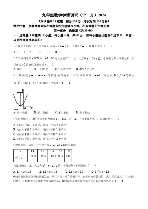
九年级数学学情调查(十一月)2024(本试卷共23道题 满分120分 考试时间120分钟)考生注意:所有试题必须在答题卡指定区域内作答,在本试卷上作答无效第一部分 选择题(共30分)一、选择题(本题共10小题,每小题3分,共30分.在每小题给出的四个选项中,只有一项是符合题目要求的)1.已知关于x 的一元二次方程的一个根是,则m 的值为( )A .1B .-2C .-1D .32.在平行四边形ABCD 中,AB ,BC 的长分别等于一元二次方程两根之和与两根之积,则对角线AC 长的取值范图是( )A .AC >1B .1<AC <5C .5<AC <19D .AC >5或<93.二次函数的图象如图所示,对称轴是直线,则过点和点的直线一定不经过( )A .第一象限B .第二象限C .第三象限D .第四象限4.将抛物线平移得到抛物线,下列平移方式中,正确的是( )A .先向左平移1个单位,再向上平移2个单位B .先向左平移1个单位,再向下平移2个单位C .先向右平移1个单位,再向下平移2个单位D .先向右平移1个单位,再向上平移2个单位5.观察表格,估算一元二次方程的近似解:1.4 1.5 1.6 1.7 1.8-0.44-0.25-0.040.190.44由此可确定一元二次方程的一个近似解x 的范围是( )A .B .C .D .6.随着我国航天领域的快速发展,从“天宫一号”发射升空,到天和核心舱归位,我国正式迈入了“空间站时代”.下面是有关我国航天领域的图标,其图标既是轴对称图形又是中心对称图形的是( )2520x x m +-=1x =27120x x -+=2y ax bx c =++1x =-(,2)M c a b -()24,N b ac a b c --+23y x =-23(1)2y x =---210x x --=x21x x --210x x --=1.4 1.5x << 1.5 1.6x << 1.6 1.7x << 1.7 1.8x <<A .B .C .D .7.如图,在△ABC 中,∠B =40°,将△ABC 绕点A 逆时针旋转得到△ADE ,点D 恰好落在BC 的延长线上,则旋转角的度数为( )A .100°B .90°C .80°D .70°8.如图,正方形ABCD 中,E 为AD 边上一点,连接BE ,将BE 绕点E 逆时针旋转90°得到EF .连接DF 、BF ,若∠DFE =,则∠CBF 一定等于( )A .B .C .D.9.如图,△ABC 和△CDE 两个全等的直角三角形,∠B =∠CDE =90°,连结AD 交CE 于点F .若,则的值为( )A .B .C .D .10.如图,在矩形ABCD 中,AB =4,延长CD 到点E ,连接BE 交AD 于点G ,点F 为BE 的中点,连接CE ,以点C 为圆心,CF 长为半径的圆弧经过点G ,连接CG ,若BE =10,则DG 的长为( )α45α- α903a - 12α12AB BC =DF AF13122523A .4B .5C .6D .3第二部分 非选择题二、填空题(本题共6小题,每小题3分,共15分)11.若a 是一元二次方程的一个根,则的值是 .12.2023年德尔塔(Delta )是一种全球流行的新冠病毒变异毒株,其传染性极强.某地有1人感染了德尔塔,因为没有及时隔离治疗,经过两轮传染后,一共有169人感染了德尔塔病毒,那每轮传染中平均一个人传染了 个人;如果不及时控制,照这样的传染速度,经过三轮传染后,一共有 人感染德尔塔病毒.13.下列命题:①若时,一元二次方程一定有实数根;②若方程有两个不相等的实数根,则方程也一定有两个不相等实数根;③若二次函数,当取时,函数值相等,则当x 取时函数值为0;④若,则二次函数图象与坐标轴的公共点的个数是2或3,其中正确结论的个数是 (填序号)14.如图所示,△ABC 中,∠C =90°,AC =8cm ,BC =6cm ,点D 从B 点开始沿BC 向B 点以1cm /s 的速度移动,点E 从C 点开始沿 CA 边向A 点以2cm /s 速度移动,如果D 、E 分别从B 、A 同时出发,那么 秒后,线段DE 将△ABC 分成面积1:2的两部分.15.如图,在△ABC 中,∠BAC =120°,AB =2,AC =4,将BC 绕点C 顺时针旋转120°得到CD ,则线段AD 的长度是.250x x +-=23310a a +-b a c =+20ax bx c ++=20ax bx c ++=20cx bx a ++=2y ax c =+()1212,x x x x ≠12x x +240b ac ->2y ax bx c =++三、解答题(本题共8小题,共75分.解答应写出文字说明、演算步骤或推理过程)16.(10分)解下列方程:(1);(2).17.(8分)如图所示,某市公园有一块长方形绿地长20,宽16,在绿地中开辟三条等宽的道路后,剩余绿地的面积为224,求道路的宽x 是多少米?18.(8分)如图,在矩形ABCD 中,AB =2AD ,∠DAB 的平分线交CD 于E .F 为BC 的中点,连结AE ,AF ,分别交BD 于点G , H .连结EF .(1)求证:BD =2EF ;(2)当EF =6时,求GH 的长.19.(8分)“弗里热”(Phryge )是2024年巴黎奥运会和残奥会吉祥物,是法国传统的弗里古亚帽的拟人化形象,在《蓝精灵》动画片中,蓝精灵戴的便是弗里吉亚帽.吉祥物“弗里热”小钥匙扣广受欢迎,成为热销商品,某商家以每套40元的价格购进一批“弗里热”小钥匙扣.当该商品每套的售价是50元时,每天可售出200套,若每套的售价每提高2元,则每天少卖4套.(1)设“弗里热”小钥匙扣每套的售价定为x 元,求该商品销售量y 与x之间的函数关系式.22125x x -+=257311x x x ++=+m m 2m(2)每天销售所获的利润W 能否恰好达到3000元?请说明理由.20.(8分)如图,鞍钢博物馆广场边,有两个高炉模型,小明同学用自制的直角三角形纸板ADE 量高炉的高度BF .他调整自己的位置,设法使斜边AE 持水平,AE 的延长线交BF 于C ,并且边AD 与点B 在同一直线上,已知纸板的两条直角边AD =40cm .DE =20cm .测得边AE 离地面的高度AG =1.5,CD =20.求高炉的高BF .21.(8分)如图,钢球从斜面顶端由静止开始沿斜面滚下,速度每秒增加1.5.(1)写出滚动的距离s (单位:)关于滚动的时间t (单位:)的函数解析式.(提示:本题中,距离=平均速度×时间t ,,其中,是开始时的速度,是t 秒时的速度.)(2)如果斜面的长是3,钢球从斜面顶端滚到底端用多长时间?22.(12分)如图,在Rt△ABC 中,∠ABC =90°,把边CB绕点C 旋转到CF .(1)若AB =.BC .当点F 落在BC 的垂直平分线上时,请直接写出以A 、B 、C 、F 为顶点的四边形的面积 .(2)如图1,连接AF ,当点F 在AC 的垂直平分线上时,若BC =2AB =4,求F 到AC 的距离;(3)如图2,连接FB 交AC 于点D ,当AC ⊥BF 时,BC 的垂直平分线分别交BC 、AC 、CF 于E 、H 、M ,交BF 的延长线于G .判断:BE 、GM 、MC 三条线段的关系,并给予证明.m m m m s v 02t v v v +=0v t v m图1 图223.(13分)已知y 关于x 的一次函数.当时,我们称一次函数为“原函数”,一次函数“原函数”的“相关函数”,“原函数”的图象记为直线,它的“相关函数”的图象记为直线.例如:“原函数”的“相关函数”为.(1)直接写出“相关函数”的“原函数”表达式;(2)请说明:直线,直线与x 轴的交点是同一个点;(3)若“原函数”的表达式为,点A 在直线上,点B 在直线上,轴,AB =2,求点A 的坐标;(4)“原函数”的表达式为.①点在直线上,点在直线上,若,求t 的取值范围;②若直线,直线与y 轴围成的图形面积为12,点E 在直线上,过E 作轴交直线于点F ,过E 作轴交直线于点H ,过F 作轴交直线于点G ,连接GH .设点E 的横坐标为,四边形 EFGH 的周长为C .直接写出C 关于a的函数表达式.y kx b =+0,0k b >>y kx b =+y kx b =--1l 2l 2y x =+2y x =--213y x =--1l 2l 112y x =+1l 2l AB y ∥2y mx m =+(),C C t y 1l ()2,D D t y -2l 0D C y y <<1l 2l 1l EF y ∥2l EH x ∥2l FG x ∥1l (0)a a >九年级数学质量测试(十一月)2024答案及评分标准说明:1.此答案仅供参考,阅卷之前请做答案.2.如果考生的解法与本解法不同,可参照本评分标准制定相应评分细则.3.为阅卷方便,本解答中的推算步骤写得较为详细,但允许考生在解答过程中,合理省略非关键性的推算步骤.4.解答右端所注分数,表示考生正确做到这一步应得的累加分数.一、单项选择题(每题只有一个选项正确.每小题3分,共30分)1.D2.C3.C4.C5.C6.B7.A8.B9.C 10.D二、填空题(每小题3分,共15分)11.512.12 2197 13.①③ 14.2或4 15.三、解答题(8道题共75分)16.(10分)解:(1)..…………………………5分(2).整理,得...…………………………5分17.(8分)解:依题意可列…………………………3分……………………………………5分(含)………………………………7分答:道路的宽是2米.…………………………8分18.(8分)(1)证明:∵四边形ABCD 是矩形,AB =2AD,22125x x -+=2(1)25x -=15x -=±126,4x x ==-257311x x x ++=+224x x +=2215x x ++=2(1)5x +=1x +=121,1x x =-=-(202)(16)224x x --=226480x x -+=12224,x x ==∴CD //AB ,AB =CD =2AD ,AD =BC ,∴∠DEA =∠BAE∵AE 平分∠DAB∴∠DAE =∠BAE ,∴∠DEA =∠DAE ,∴DE =AD∵CD =2AD∴CD =2DE .∴DE =CE∵F 为BC 的中点,∴EF 是△BCD 的中位线,∴BD =2EF ;…………………………………4分(2)解:由(1)知,BD =2EF ,∵EF =6∴BD =12∵AB =CD =2AD =2DE ,AD =BC ,F 为BC 的中点,∴.在矩形ABCD 中,CD //AB ,AD //BC ,∴△DEG ∽△BAG ,△FBH ∽△ADH ,,.∴DG =4,BH =4∴GH =BD -DG -BH =4……………………………………………………8分19.(8分)解:(1)根据题意:.∴y 与x 之间的函数关系式:;…………………………4分(2)根据题意得:.整理得:.∵.∴方程有两个不相等的实数根,∴每天销售所获的利润W 能达到3000元.………………………………8元20.(8分)…………………………………………8分21.(8分)解:(1)由已知得11,22DE BP AB AD ==11,22DE DG BH BF AB BG DH AD ∴====11,122122DG BH DG BH ∴==--50200423002x y x -=-⨯=-+2300y x =-+(40)(2300)3000x x --+=219075000x x -+=2Δ(190)41750061000=--⨯⨯=>11.5m 00 1.5 1.5t v v at t t=+=+=,即………………………………4分(2)把代入中,得(舍去)即钢球从斜面顶端滚到底端用.答:钢球从斜面顶端滚到底端用.……………………………………8分22.(12分)解:(12分解:(2)如图1,过点F作FG⊥AC于G,∵FA=FC,∴CG=AG=AC∵∠ABC=90°,∴∴.∵CF=BC=4..∴点F到AC;……………………6分(2)BE+GM=MC…………………………7分证明:如图2,延长EG至K.使KG=AB.连接AK.∵AB⊥BC,EG⊥CB.∴EG∥AB,∴四边形ABKG是平行四边形,∴AK=BC,∠AKG=∠ABD.∵FC=CB∴∠FCD=∠ACB∵∠ABC=∠BGE=90°.∴∠BAC+∠ACB=90°.∵∠BDC=90°,∴∠ACB+∠EBG=90°,∴∠BAC=∠EBG.∵AB=BE∴△ABC≌△BEG(ASA)∴AC=BG.1.5t3t224tv vv+∴===233244tv v ts vt t t t+∴==⋅=⋅=234s t=3s=234s t=2t=2t=-2s2s12AC===CG=FG∴===∴AK =AC .∴∠AKC =∠ACK同理可得,∠ABD =∠ACB∴∠ABD =∠FCD∴∠AKG =∠FCD .∴∠AKC -∠AKG =∠ACK -∠FCD .∴∠MKC =∠MCK .∴CM =KM =CK +GM =BE +GM …………………………………12分图1 图223.解:(1);……………………………………1分(2)在“原函数”中,令.则.∴直线与x 轴交点为在它的“相关函数”,令,则∴直线与x 轴交点为∴直线,直线与x 轴的交点为同一个点;…………………………4分(3)∵“原函数”的表达式为∴它的“相关函数”表达式为.令∴.∴直线与直线的交点为∵点A 在直线上.213y x =+y kx b =+0kx b +=b x k =-1l ,0b k ⎛⎫- ⎪⎝⎭y kx b =--0kx b --=bx k =-2l ,0b k ⎛⎫- ⎪⎝⎭1l 2l 112y x =+112y x =--111122x x +=--2x =-1l 2l (2,0)-1l∴设,如图1,当时,点A 在点B 上方∵AB ∥y 轴.∴∴点,,当时,点A 在点B 的下方,A (-4,-1)综上所述,点A 的坐标为A (0,1)或A (-4,-1);………………………………8分(4)①∵“原函数”为.∴它的“相关函数“为.令..∴直线与直线交点为(-2,0);如图2,∵点C 在直线上,点D 在直线,且.,且,,.,∴t 的取值范围为.……………………11分1,12A a a ⎛⎫+ ⎪⎝⎭2a >-A B x x a==1,12B a a ⎛⎫-- ⎪⎝⎭1111222a a ∴+++=0a ∴=(0,1),A ∴2a <-2y mx m =+2y mx m =--20mx m +=2x ∴=-1l 2l 1l 2l 0D C y y <<222t t -<-⎧∴⎨>-⎩20t ∴-<<2,(2)2c D y mt m y m t m =+=--- D Cy y <(2)22m t m mt m ∴---<+22mt m ∴>-20m > 1t ∴>-10t -<<②如图3,直线与直线交点为Q (-2,0),∴OQ =2,OM =ON =2m ,∴MN =4m ,,∴m =3,∴“原函数“表达式为.它的“相关函数”表达式为,轴交于点F ,,∵EH ∥x 轴,,,,..∵FG ∥x 轴,,.1l 2l 1122MN OQ ∴⋅=142122m ∴⨯⨯=36y x =+36y x =--(,36)E a a ∴+EF y ∥2l (,36),F a a ∴--36(36)612EF a a a ∴=+---=+36E H y y a ∴==+3636a x ∴+=--4x a ∴=--(4,36)H a a ∴--+(4)24EH a a a ∴=---=+36G F y y a ∴==--3636a x ∴--=+4x a ∴=--(4,36)G a a ∴----.又∵轴,轴,∴FG∥EH,∴四边形EFGH为平行四边形,. (13)分(4)2 4.FG a a a∴=---=+2 4.FG EH a∴==+//FG x//EH x2()2(61224)1632 C EF FG a a a∴=+=+++=+。

轨道不平顺质量指数(TQI)解析及养护指导意见一、峰值管理法与均值管理法的定义及两者之间的比较(1)峰值管理法:衡量轨道局部不平顺的方法,典型的是轨道Ⅰ、Ⅱ、Ⅲ、Ⅳ级超限的管理。
峰值扣分法是从轨道的几何尺寸指标和舒适度指标的角度,以1千米为单位计算总扣分的方式来评定轨道的质量的评定方法。
峰值管理法的数据采集原理:车辆每行进一英尺(约254mm,俗称1米4个点),计算机对各检测项目采集一次,当某项连续三次采集量都超过最低级病害界限值时,计算机统计为一处超限病害,并取病害最大采集量值为该处超限病害的幅值,最低级超限病害起终点为该处病害长度的起终点,如上图1、2、3分别表示Ⅰ、Ⅱ、Ⅲ级病害界限值,A、B、C、D分别表示四个采集点,由采集原理得知,此处计算机将统计为一处病害:B 点的幅值为该病害幅值,L表示超限病害长度,该病害为Ⅲ级超限。
(2)均值管理法:衡量线路区段整体不平顺的方法。
这种方法是测量并记录被测轨道区段中全部测点的幅值,所有幅值都作为轨道状态的一个元素参与运算,同时还选择若干单项几何参数的指数进行加权计算获得综合指数,即用统计特征值来评价轨道区段的质量状态。
目前主要用的方法有:轨道质量指数(TQI)、轨道功率谱等。
(3)峰值管理法与均值管理法两者之间的比较峰值管理法能够找出轨道的局部病害及病害的类型、发展程度和所在位置,用于指导现场作紧急维修养护非常实用,但是仅用超限点峰值的大小、超限的数量及扣分多少,还不能全面、科学、合理地评价轨道区段的平均质量状态。
峰值管理法的缺点:①轨道动态检查标准对检测结果的影响比较大;②三、四级超限扣分占的权重比较大;③检测系统误差的影响较大;④不能反映超限长度的影响;⑤不能反映轨道不平顺变化率和周期性连续不平顺所产生的谐波的影响。
均值管理法的优点:①能真实全面反映轨道质量状态,准确反映轨道恶化程度,用数据明确表示各个区段好坏;②可作为各级工务部门对轨道状态进行宏观管理和质量控制的依据,有利于编制轨道维修计划,指导养护维修作业;③TQI数值与轨道质量状态对应关系明确,易于被现场人员掌握和利用。

Designation:D1003–00Standard Test Method forHaze and Luminous Transmittance of Transparent Plastics1 This standard is issued under thefixed designation D1003;the number immediately following the designation indicates the year of original adoption or,in the case of revision,the year of last revision.A number in parentheses indicates the year of last reapproval.A superscript epsilon(e)indicates an editorial change since the last revision or reapproval.This test method has been approved for use by agencies of the Department of Defense to replace Method3022of Federal Test Method Standard406.1.Scope1.1This test method covers the evaluation of specific light-transmitting and wide-angle-light-scattering properties of planar sections of materials such as essentially transparent plastic.Two procedures are provided for the measurement of luminous transmittance and haze.Procedure A uses a hazeme-ter as described in Section5and Procedure B uses a spectro-photometer as described in Section8.Material having a haze value greater than30%is considered diffusing and should be tested in accordance with Practice E167.1.2The values stated in SI units are to be regarded as the standard.N OTE1—For greater discrimination among materials that scatter a high percent of light within a narrow forward angle,such as is the case with abraded transparent plastics,adjust the hazemeter and perform measure-ments in accordance with Test Method D1044.1.3This standard does not purport to address all of the safety concerns,if any,associated with its use.It is the responsibility of the user of this standard to establish appro-priate safety and health practices and determine the applica-bility of regulatory limitations prior to use.N OTE2—This test method is not equivalent to ISO13468–1and ISO/DIS14782.2.Referenced Documents2.1ASTM Standards:D618Practice for Conditioning Plastics and Electrical Insulating Materials for Testing2D883Terminology Relating to Plastics2D1044Test Method for Resistance of Transparent Plastics to Surface Abrasion2D1898Practice for Sampling of Plastics2E167Practice for Goniophotometry of Objects and Mate-rials3E259Practice for Preparation of Reference White Reflec-tance Standards3E284Terminology of Appearance3E691Practice for Conducting an Interlaboratory Test Pro-gram to Determine the Precision of a Test Method42.2ISO Standards:5ISO13468–1Plastics—Determination of the Total Lumi-nous Transmittance of Transparent MaterialsISO/DIS14782Plastics—Determination of Haze of Trans-parent Materials3.Terminology3.1Definitions—Terms applicable to this test method are defined in Terminologies D883and E284.3.2Definitions of Terms Specific to This Standard:3.2.1haze,n—in transmission,the scattering of light by a specimen responsible for the reduction in contrast of objects viewed through it.The percent of transmitted light that is scattered so that its direction deviates more than a specified angle from the direction of the incident beam.3.2.1.1Discussion—In this test method,the specified angle is0.044rad(2.5°).3.2.2luminous,adj—weighted according to the spectral luminous efficiency function V()of the CIE(1987).3.2.3luminous transmittance,n—the ratio of the luminous flux transmitted by a body to theflux incident upon it.4.Significance and Use4.1Light that is scattered upon passing through afilm or sheet of a material can produce a hazy or smokyfield when objects are viewed through the material.Another effect can be veiling glare,as occurs in an automobile windshield when driving into the sun.4.2Although haze measurements are made most commonly by the use of a hazemeter,a spectrophotometer may be used, provided that it meets the geometric and spectral requirements of Section5.The use of a spectrophotometer for haze mea-surement of plastics can provide valuable diagnostic data on1This test method is under the jurisdiction of ASTM Committee D20on Plastics and is the direct responsibility of Subcommittee D20.40on Optical Properties.Current edition approved June10,2000.Published July2000.Originallypublished as D1003–st previous edition D1003–97e1.2Annual Book of ASTM Standards,V ol08.01.3Annual Book of ASTM Standards,V ol06.01.4Annual Book of ASTM Standards,V ol14.02.5Available from American National Standards Institute,11W.42nd St.,13th Floor,New York,NY10036.1Copyright©ASTM International,100Barr Harbor Drive,PO Box C700,West Conshohocken,PA19428-2959,United States.the origin of the haze,6and Procedure B is devoted to the use of a spectrophotometer.4.2.1Procedure A(hazemeter)test values are normally slightly higher and less variable than Procedure B(spectropho-tometer)test values.4.3Regular luminous transmittance is obtained by placing a clear specimen at some distance from the entrance port of the integrating sphere.However,when the specimen is hazy,the total hemispherical luminous transmittance must be measured by placing the specimen at the entrance port of the sphere.The measured total hemispherical luminous transmittance will be greater than the regular luminous transmittance,depending on the optical properties of the sample.With this test method,the specimen is necessarily placed at the entrance port of the sphere in order to measure haze and total hemispherical luminous transmittance.4.4Haze data representative of the material may be ob-tained by avoiding heterogeneous surface or internal defects not characteristic of the material.4.5Haze and luminous-transmittance data are especially useful for quality control and specification purposes.4.6Before proceeding with this test method,reference should be made to the specification of the material being tested. Any test specimen preparation,conditioning,dimensions,or testing parameters,or combination thereof,covered in the materials specification shall take precedence over those men-tioned in this test method.If there are no material specifica-tions,then the default conditions apply.5.Test Specimens5.1Sample the material in accordance with Practice D1898.Obtain specimens that are free of defects not charac-teristic of the material unless such defects constitute variables under study.5.2Cut each test specimen to a size large enough to cover the entrance port of the sphere.A disk50mm(2in.)in diameter,or a square with sides of the same dimensions,is suggested.The specimen shall have substantially plane-parallel surfaces free of dust,grease,scratches,and blemishes,and it shall be free of visibly distinct internal voids and particles, unless it is specifically desired to measure the contribution to haze due to these imperfections.5.3Prepare three specimens to test each sample of a given material unless specified otherwise in the applicable material specification.6.Conditioning6.1Conditioning—Unless otherwise required in the appro-priate materials specification or agreed between customer/ supplier,condition the test specimens at2362°C(73.46 3.6°F)and5065%relative humidity for not less than40h prior to test,in accordance with Procedure A of Practice D618. In case of disagreements,the tolerances shall be61°C(1.8°F) and62%relative humidity.6.2Test Conditions—Set up the test apparatus in an atmo-sphere maintained at2362°C(73.463.6°F)and5065% relative humidity.7.Procedure A—Hazemeter7.1Apparatus:7.1.1The instrument used for measurement shall meet the geometric and spectral requirements of this section.77.1.2A light source and a photodetector shall be supplied, and the combination shall befiltered to provide an output corresponding to the luminosity response of the1931CIE Standard Colorimetric Observer with CIE Standard Illuminant C or,alternatively,Illuminant A.The output shall be propor-tional to within1%to the incidentflux over the range offlux used.The photometric stability for source and detector must be constant throughout the test of each specimen.7.1.3Use an integrating sphere to collect transmittedflux; the sphere may be of any diameter as long as the total port areas do not exceed4.0%of the internal reflecting area of the sphere.The entrance and exit ports shall be centered on the same great circle of the sphere,and there shall be at least2.97 rad(170°)of arc between centers.The exit port shall subtend an angle of0.14rad(8°)at the center of the entrance port.With the light trap in position,without the specimen,the axis of the irradiating beam shall pass through the centers of the entrance and exit ports.For a hazemeter,position the photocell or photocells on the sphere1.5760.17rad(90610°)from the entrance port and baffle it from direct exposure to the entrance port.In the pivotable modification where the interior wall adjacent to the exit port is used as the reflectance reference,the angle of rotation of the sphere shall be0.14060.008rad(8.0 60.5°).7.1.4Illuminate the specimen by a substantially unidirec-tional beam;the maximum angle that any ray of this beam may make with the beam axis shall not exceed0.05rad(3°).This beam shall not be vignetted at either port of the sphere.7.1.5When the specimen is placed against the entrance port of the integrating sphere,the angle between the perpendicular to the specimen and a line connecting the centers of entrance and exit ports shall not exceed0.14rad(8°).7.1.6When the beam is unobstructed by a specimen,its cross section at the exit port shall be approximately circular, sharply defined,and concentric within the exit port,leaving an annulus of0.02360.002rad(1.360.1°)subtended at the entrance port.N OTE3—It is important to verify whether the unobstructed-beam diameter and centering at the exit port are maintained,especially if the source aperture and focus are changed.N OTE4—The tolerance stated on the annulus of0.002rad(0.1°) corresponds to an uncertainty of60.6%in a haze reading.8This is relevant for assessing the precision and bias of this test method.6Billmeyer,F.W.,Jr.,and Chen,Y.,“On the Measurement of Haze,”Color Research and Application,V ol10,1985,pp.219–224.7Hazemeters made by BYK-Gardner,Inc.,2435Linden Lane,Silver Spring, MD20910,meet these requirements.Other manufacturers of this equipment,which meet the requirements,may exist but have not been identified.8Weidner,V.R.,and Hsia,J.J.,“NBS Reference Hazemeter:Its Development and Testing,”Applied Optics,V ol18,1979,pp.1619–1626.7.1.7The surfaces of the interior of the integrating sphere,baffles,and reflectance standard,if used,shall be of equal reflectance,matte,and highly reflecting throughout the visible spectrum.97.1.8A light trap shall be provided that will absorb the beam completely when no specimen is present,or the instrument design shall obviate the need for a light trap.7.1.9A schematic drawing of the optics of a hazemeter with unidirectional illumination and diffuse viewing is shown in Fig.1.7.1.10A series of calibrated haze standards is required for periodic verification of the accuracy of instrumental response.Ideally,if the haze of narrow-angle-scattering specimens (such as plastic films)is to be measured,narrow-angle-scattering glass standards should be used;7,8however,these are not known to be commercially available.In their absence,wide-angle-plastic standards 10may be used,but these are less sensitive to the size and centering of the annulus described by Billmeyer and Chen 6and Weidner and Hsia,9and particular attention should be paid to Note 1when only plastic haze standards are used.7.2Procedure :7.2.1Determine the following four readings:Reading DesignationSpecimen in PositionLight Trap in PositionReflectance Standard in PositionQuantity Represented T 1no no yes incident lightT 2yes no yes total light transmitted by specimenT 3no yes no light scattered by instru-mentT 4yesyesnolight scattered by instru-ment and specimen7.2.2Repeat readings for T 1,T 2,T 3,and T 4with additional specified positions of the specimen to determine uniformity.7.3Calculation 11:7.3.1Calculate total transmittance,T t (Note 5),equal to T 2/T 1.7.3.2Calculate diffuse transmittance,T d (Note 5),as fol-lows:T d 5@T 42T 3~T 2/T 1!#/T 1(1)7.3.3Calculate percent haze as follows:haze 5T d /T t 3100(2)N OTE 5—To obtain the greatest accuracy in luminous transmittance measurement when using a single-beam instrument,it is necessary to use a standard,calibrated with a double-beam instrument,because insertion of the sample in the single-beam instrument changes the efficiency of the sphere.This change may result in spuriously high readings for clear,colorless samples and significant errors for dark or highly saturated colors.In these cases,the photometer should be used as a comparison instrument with a standard of known transmittance similar to that of the specimen.For greatest accuracy of luminous transmittance measurement,compare the transmittance of the specimen with that of a calibrated standard of similar luminous transmittance.7.4Report :7.4.1Report the following data:7.4.1.1Source and identity of specimen,7.4.1.2Nominal thickness of specimen to the nearest 0.025mm,7.4.1.3Total luminous transmittance,T t ,to the nearest 0.1%(indicate the average when reporting average values and specify whether CIE Illuminant C or A is used),7.4.1.4Diffuse luminous transmittance,T d ,to the nearest 0.1%(indicate the average when reporting average values),and7.4.1.5Percent haze,to the nearest 0.1%(indicate the average when reporting average values).7.5Precision and Bias—Hazemeter :7.5.1Precision :7.5.1.1Table 1and Table 2are based on a round robin conducted in 1985,in accordance with Practice E 691,involv-ing six film materials tested by 11laboratories.In the round robin,each laboratory that measured a property made eight replicate measurements of the property for each of the six materials listed as 1to 6in Table 1and Table 2.7.5.1.2Table 3is based on a round robin conducted in 1991involving eight materials and six laboratories.This table can be directly compared to Table 4(Spectrophotometer).N OTE 6—Caution:The following explanations of r and R (7.5.1.3-7.5.1.7)are intended to present only a meaningful way of considering the approximate precision of this test method.The data in Tables 1-3should not be applied rigorously to acceptance or rejection of material,as those data are specific to the round robin and may not be representative of other9Highly reflective matte barium sulfate paint or pressed polytetrafluoroethylene powder are excellent for this purpose.See Practice E 259.10Calibrated plastic haze standards are available from BYK-Gardner,Inc.,2435Linden Lane,Silver Spring,MD 20910.11See Appendix X1for derivation offormulas.FIG.1Schematic of HazemeterTABLE 1Summary of 1985Procedure A (Hazemeter)Total HazeRound Robin Involving Eleven LaboratoriesMaterial Average S(r)S(R)r R 3 3.80.100.330.280.9418.70.180.420.50 1.18213.50.080.400.23 1.12418.00.270.610.76 1.72521.00.41 1.68 1.16 4.74626.50.351.130.983.19lots,conditions,materials,or ers of this test method should apply the principles outlined in Practice E 691to generate data specific to their laboratory and materials,or between specific laboratories.The principles of 7.5.1.3-7.5.1.7would then be valid for such data.7.5.1.3For the purpose of compiling summary statistics,a test result has been defined to be the average of three replicate measurements of a property for a material in a laboratory,as specified in this test method.Summary statistics are given in Tables 1-3.In each table,for the material indicated,S(r)is the pooled within-laboratory standard deviation of a test result,S(R)is the between-laboratory standard deviation of a test result,r =2.833S(r)(see 7.5.1.4),and R =2.833S(R)(see 7.5.1.5).7.5.1.4Repeatability —Two test results obtained within one laboratory shall be judged not equivalent if they differ by morethan the “r ”value for that material.“r ”is the interval representing the critical difference between two test results for the same material,obtained by the same operator using the same equipment on the same day in the same laboratory.7.5.1.5Reproducibility —Two test results obtained by dif-ferent laboratories shall be judged not equivalent if they differ by more than the “R ”value for that material.“R ”is the interval representing the critical difference between two test results for the same material,obtained by different operators using differ-ent equipment in different laboratories.7.5.1.6Judgments made as described in 7.5.1.3and 7.5.1.4will be correct in approximately 95%of such comparisons.7.5.1.7For further information,see Practice E 691.7.5.2Bias —Measurement biases cannot be determined since there are no accepted referee methods for determining these properties.8.Procedure B (Spectrophotometer)8.1Apparatus :8.1.1The instruments used for measurement shall meet the geometric and spectral requirement of this section.8.1.2The instrument shall be capable of computing from the spectral data the 1931CIE tristimulus values and related color coordinates for CIE standard Illuminant C or alterna-tively Illuminant A.8.1.3The instrument shall utilize a hemispherical optical measuring system,with an integrating sphere,in which the specimen can be placed flush against the sphere port.The surfaces of the interior of the integrating sphere,baffles,and reflectance standards shall be matte,of substantially equal reflectance and highly reflecting throughout the visible wave-lengths.8.1.4Two geometries can be used:unidirectional illumina-tion with diffuse viewing and diffuse illumination with unidi-rectional ing Geometry B the following apply:8.1.4.1Use an integrating sphere to illuminate the specimen diffusely;the sphere may be of any diameter as long as the total port areas do not exceed 4.0%of the internal reflecting area of the sphere.The specimen and light trap ports of the sphere shall be centered on the same great circle of the sphere,and there shall be at least 2.97rad (170°)of arc between their centers.The light trap port shall subtend an angle of 0.14rad (8°)at the center of the specimen port along the wowing beam.With the light trap in position,without specimen the axis of the viewing beam shall pass through the centers of the specimen and light trap ports.8.1.4.2View the specimen along an axis defined by a substantially unidirectional beam;the maximum angle that any ray of this beam may make with the beam axis shall not exceed 0.05rad (3°).This beam shall not be vignetted at either port of the sphere.8.1.4.3When the specimen is in place,the angle between the specimen normal and the line connecting the centers of the specimen and the light trap ports shall not exceed 0.14rad (8°).8.1.4.4With no specimen in place,the viewed area at the exit port shall be approximately circular,sharply defined concentric within the light trap port,leaving an annulus of 0.02360.002rad (1.360.01°)subtended at the specimen port.TABLE 2Summary of 1985Procedure A (Hazemeter)Luminous Transmittance Round Robin Involving Eleven LaboratoriesMaterial Average S(r)S(R)r R 283.60.25 1.210.69 3.42484.80.15 1.060.42 3.02186.40.08 1.080.22 3.06387.50.20 1.070.57 3.02688.50.14 2.100.38 5.93588.60.352.230.996.32TABLE 3Summary of 1991Procedure A (Hazemeter)Total HazeRound Robin Involving Six LaboratoriesMaterial Average S(r)S(R)r R LDPE A 0.580.0310.1330.0860.372B 1.890.0290.2160.0800.604C 2.080.0210.2000.0580.568PET D 2.690.0420.3130.1170.075E 5.740.0310.3950.086 1.106F 8.060.0490.5660.137 1.584G 12.680.0500.4900.140 1.372H28.570.0911.0420.2562.9918TABLE 4Summary of 1991Procedure B (Spectrophotometer)Total Haze Round Robin Involving Seven LaboratoriesMaterial Average S(r)A S(R)B r C R D LDPE A 0.550.0760.1860.2130.522B 1.770.0870.6580.244 1.019C 1.010.0420.3970.175 1.112PET D 2.510.1150.3310.3230.927E 5.050.0810.5960.227 1.669F 6.550.189 1.1380.305 3.186G 11.350.137 1.2890.385 3.610H25.450.1583.0200.4438.455AS r is the within laboratory standard deviation for the indicated material.It is obtained by pooling the within-laboratory standard deviations of the test results from all of the participating laboratories:S r 5@@~s 1!21~s 2!2...1~s n !2#/n #½BS R is the between laboratories reproducibility,expressed as standard devia-tion:S R 5@s r 21s L 2#½where:s L =standard deviation of laboratory means.Cr is the within-laboratory critical interval between two test results =2.83S r .DR is the between-laboratories critical interval between two test results =2.83S R.N OTE 7—Note 3and Note 4apply.It should be noted that it may be difficult,but is critical,to meet this requirement.8.1.5A light trap shall be provided that will completely absorb the beam when no specimen is present,or the instru-ment design shall obviate the need for a light trap.8.1.6A schematic drawing of a spectrophotometer with unidirectional illumination and diffuse viewing is shown in Fig.2.N OTE 8—It is strongly recommended that conformance to the intent of this test method be confirmed through use of properly calibrated haze standards due to the difficulty of confirming conformance to this test method when using a drill spectrophotometer.8.2Procedure —Follow the manufacturer’s instructions for the measurement of haze,and if none available,use Section 8.8.3Calculation —Most spectrophotometers are computer driven and values for luminous transmission and haze are automatically calculated.If values are not computed use calculation method in Section 9.8.4Report :8.4.1Report the following data:8.4.1.1Source and identity of specimen,8.4.1.2Nominal thickness of specimen,8.4.1.3Percent haze,to the nearest 0.1%(indicate the average when reporting average values),8.4.1.4Total luminous transmittance,T t ,to the nearest 0.1%(indicate the average when reporting average values and specify whether CIE Illuminant C or A is used)when specifi-cally requested,and8.4.1.5Diffuse luminous transmittance,T d ,to the nearest 0.1%(indicate the average when reporting average values)when specifically requested.8.5Precision and Bias :8.5.1Precision :8.5.1.1Precision data in Table 4is based on a round robin conducted in 1991involving eight materials and seven labo-ratories.For comparison purposes the same materials were measured on six regular hazemeters during the same round robin.The data from the regular hazemeter round robin is included in Table 3.N OTE 9—Caution:The following explanations of r and R (8.5.1.2-8.5.1.6)are intended to present only a meaningful way of considering the approximate precision of this test method.The data in Tables 1-4should not be applied rigorously to acceptance or rejection of material,as those data are specific to the round robin and may not be representative of other lots,conditions,materials,or ers of this test method should apply the principles outlined in Practice E 691to generate data specific to their laboratory and materials,or between specific laboratories.The principles of 8.5.1.2-8.5.1.6would then be valid for such data.8.5.1.2For the purpose of compiling summary statistics,a test result has been defined to be the average of three replicate measurements of a property for a material in a laboratory,as specified in this test method.Summary statistics are given in Table 4.In each table,for the material indicated,S(r)is the pooled within-laboratory standard deviation of a test result,S(R)is the between-laboratory standard deviation of a test result,r =2.833S(r)(see 8.5.1.3),and R =2.833S(R)(see 8.5.1.4).8.5.1.3Repeatability —In comparing two mean values of the same material,obtained by the same operator using the same equipment on the same day,the means should be judged not equivalent if they differ by more than the r value for that material.8.5.1.4Reproducibility —In comparing two mean values for the same material obtained by different operators using differ-ent equipment on different days,either in the same laboratory or in different laboratories,the means should be judged not equivalent if they differ by more than the R value for that material.8.5.1.5Judgments made as described in 8.5.1.3and 8.5.1.4will be correct in approximately 95%of such comparisons.8.5.1.6For further information,see Practice E 691.8.5.2Bias —Measurement biases cannot be determined since there are no accepted referee methods for determining these properties.9.Referee Procedure9.1In case of dispute,Procedure A—Hazemeter will be the referee procedure measured with a standard hazemeter.10.Keywords10.1haze;luminous transmittance;regular transmittance;transparentplasticsFIG.2Spectrophotometer With DiffuseIlluminationAPPENDIXES(Nonmandatory Information)X1.DERIV ATION OF FORMULAS FOR HAZEX1.1The derivation of the formula for haze for both procedures is as follows:X1.1.1Total luminous transmittance,T t,is calculated as follows:T t5T2/T1(X1.1)where:T2=total light transmitted by the specimen,andT1=incident light.X1.1.2If T3,the light scattered by the instrument,is zero, the diffuse luminous transmittance,T d,is calculated as follows:T d5T4/T1(X1.2)where:T4=light scattered by the instrument and specimen.X1.1.3If T3is greater than zero due to light scattered by the instrument,the total scattered light,T4,will be greater than the light scattered by the specimen by an amount proportional to T3 and equal to T3times T2/T1.The corrected amount of light scattered by the specimen will then be the following:T42T3~T2/T1!(X1.3) X1.1.4The diffuse luminous transmittance,T d,is then calculated as follows:T d5@T42T3~T2/T1!#/T1(X1.4) X1.1.5Percent haze is then calculated from the ratio of diffuse,T d,to total luminous transmittance,T t,as follows:haze,%5~T d/T t!3100(X1.5) 5@~T42T3~T2/T1!#/T14~T2/T1!#31005@~T42T3~T2/T1!#/T2!31005@~T4/T2!2~T3/T1!#3100X2.ALTERNATIVE HAZE(SHORTCUT)PROCEDUREX2.1Many commercial hazemeters have indicating sys-tems and a means of adjusting the light scattered by the instrument to zero and the total light transmitted by the specimen to100.For these instruments,the following is a shortcut method that can be used for determining haze.N OTE X2.1—This shortcut procedure may produce erroneous values for highly absorbing samples,or those measured in a stopped-down beam mode(as for Tabor abrasion haze).With such samples,instrument stray light may not be properly accounted for.It is recommended that in such situations a comparison be made of the standard procedure and the shortcut procedure using typical samples.In case of any disagreement,the standard procedure shall be considered to produce the correct values.X2.1.1With the hazemeter set to measure total transmit-tance,adjust the instrument output to read100.0.X2.1.2With the hazemeter set to measure light scattered by the instrument,adjust the instrument output to read0.0.X2.1.3With the hazemeter set to measure total transmit-tance,place the test specimen against the entrance port of the integrating sphere.X2.1.4Adjust the instrument output to read100.0.X2.1.5Set the instrument to measure light scattered by the specimen and record the reading as percent haze.ASTM International takes no position respecting the validity of any patent rights asserted in connection with any item mentioned in this ers of this standard are expressly advised that determination of the validity of any such patent rights,and the risk of infringement of such rights,are entirely their own responsibility.This standard is subject to revision at any time by the responsible technical committee and must be reviewed everyfive years and if not revised,either reapproved or withdrawn.Your comments are invited either for revision of this standard or for additional standards and should be addressed to ASTM International Headquarters.Your comments will receive careful consideration at a meeting of the responsible technical committee,which you may attend.If you feel that your comments have not received a fair hearing you should make your views known to the ASTM Committee on Standards,at the address shown below.This standard is copyrighted by ASTM International,100Barr Harbor Drive,PO Box C700,West Conshohocken,PA19428-2959, United States.Individual reprints(single or multiple copies)of this standard may be obtained by contacting ASTM at the above address or at610-832-9585(phone),610-832-9555(fax),or service@(e-mail);or through the ASTM website().。

俄语日常用语 3 00 句海外工作人员俄语日常用语300句 一.问候语1 3gpaBCTB (音译:(zi 的辣斯特威接) 您好!(你们好!) 没有汉字的译音,用拼音代替,带有下划线的汉字要读重音) p0e pbiKpbiK Cu6(备注: 6 6 6 2、 fl0 3、从0 4、 从0 5、6、7、 雾特拉) 界倪) 外切了) 早安!(早晨好!) 日安!(中午好!) 晚上好! 谢谢! 不客气! 请!(不客气!) 节日好! 新年好! (音译o 舵不拉耶 g (e|H 译;!舵不勒衣 B ewe p!不勒衣 [音译:斯吧Sei 巴 Cn He 口0冰ajyKC T 音译:拔绕路衣斯达) 3gHu (音译M 斯 扑娜子德阔姆) bIM 『(音译0斯!诺味姆郭荡姆) 3 a HT ((音译:聂砸室舵) 8、 C n p a 9、 C H 0 B 10、 P a g11、 K a K 12、 P a g ( 13、 n p u B 14、 3 g p a 15、 K a K 16、 C n a c 17、 C n a c 呢? 18、 C a g u •- 告另 ' 19、 0c 20、 0 3 21、 a 0 c 22、 B c e r 23、 M H e24、 H e n 25、 n p u x 26、 C a c 27、 n u m u 们。
28、 E J a r 切接待二 iRd 识 与 介 29、 a 八- 与■ 丿1 30、 p a 3 p 31、 n 0 3 B 32、 K a K 33、 M e H 刃 34、 n 0 3 H Bac npuB (音译c 拉特0哇斯T 扑离外ci 特哇哇齐) 向您表示问候。
n?u (音译:喀克哇谁借辣?) Ba c (音译u 拉特T 哇斯为借骑) CTB y 音译:扌H E 丽a 外特斯特乌优 TByKT (音译:e 子的辣斯特威接 冰U 音译:T 喀克为Rei 无哟借? BC Ba a )eTBbl 6 6您近况如何? 很高兴见到您。

SWIFTMT103简介及栏位详解MT103 (单笔客户汇款) 简介及栏位细解一.业务背景涵盖了所有MT100的内容,并使其更加结构化;为支持会员银行为自己的客户提供更好的服务,提供和谐一致明了的需求栏位;为欧元的实施提供必要栏位(2种货币);响应FATF(监察通过银行洗钱的组织)的要求,建立必要的栏位;支持SWIFT服务承诺协议;准许延伸汇款资料的使用。
二.MT103报文根据报文使用业务状况以三种不同的方式被交换。
1.核心MT103是通用报文,收发此类电文无须进行用户使用组别登记。
除了77T(信函内容)栏位,用户可以使用MT103报文中所有其它栏位。
2.MT103+是通用报文,收发此类电文无须进行用户使用组别登记,但收发双方有协议。
用户应使用MT103栏位和格式限制,在报文中使用规定代码使报文自动化处理。
(MT103+使用时,规定在报头{3:{119:XXX}}中必须标明代码字STP)MT103+是核心MT103的兼容子集并且独立于 MT103,SWIFT对它的网络监查更加严格。
3.MT103延伸汇款资料使用组准许它的签署者使用包含大量延伸汇款资料的77T栏位。
这些汇款资料可随意在非SWIFT格式中使用,例如:EDIFACT 或ANSI-X12。
希望使用MT103延伸汇款资料的收、发用户事先必须进行延伸汇款资料使用组登记。
我行目前接收和使用的是第一种方式核心MT103。
三.MT103定义这类报文格式是由汇款行或受汇款行委托的银行直接或通过代理行发送给另一家银行。
用来发送付款指示的报文格式。
从发报行的角度看,汇款人和收款人中至少一方是非金融机构。
该报文格式只能用于发送无条件的付款指示。
它不能用于向托收行发送光票托收(支票)项下的付款通知。
四.MT103结构图MT103 Single Customer Credit TransferStatus Tag Field Name Content/OptionsM 20 Sender’s Reference 16x-------->O13C Time indication /8c/4!n1!x4!n--------|M 23B Bank Operation Code 4!c--------->O 23E Instruction Code 4!c[/30x]---------|O 26T Transaction Type Code 3!aM 32A Value Date/Currency/Interbank SettledAmount 6!n3!a15dO 33B Currency/Instructed Amount 3!a15dO 36 Exchange Rate 12dM 50a Ordering Customer A or KO 51A Sending Institution [/1!a][/34x]4!a2!a2!c[3!c]O 52a Ordering Institution A or DO 53a Sender’s Correspondent A,B or DO 54a Receiver’s Correspondent A,B or DO 55a Third Reimbursement Institution A,B or D O 56a Intermediary Institution A,C or DO 57a Account With Institution A,B,C or DM 59a Beneficiary Customer A or no letteroptionO 70 Remittance Information 4*35xM 71A Details of Charges 3!a---?O 71F Sender’s Charges 3!a15d----|O 71G Receiver’s Charges 3!a15dO 72 Sender to Receiver Information 6*35xO 77B Regulatory Reporting 3*35xO 77T Envelope Contents 9000zM=Mandatory O=Optional五.MT100与MT103的比较:变化 MT100 MT103栏位名称改变 20 Transaction Reference Number32A Value date. CurrencyCode. Amount70 Details of Payment 20 Sender’s Reference 32A Value date, Currency.Interbank settledAmount70 Remittance Information可选项改变 56a A,DIntermediary57a A,B or DAccount WithInstitution 56a A,CorDIntermediaryInstitution57a A,B,C or DAccount withInstitution栏位标记改变 50 Ordering Customer 59 BeneficiaryCustomer 50a 50A or 50K Ordering Customer59a 59A or 59BeneficiaryCustomer费用状况 71A Details of Charges Optional 71 Details of Charges Mandatory新增栏位 13C Time indication23B Bank OperationCode23E Instruction Code26T Transaction TypeCode33B Currency/Instructed Amount36 Exchange rate51A Sending Institution55a ThirdReimbursementInstitution71F Sender’s Charges71G Receiver’s Charges77B RegulatoryReporting77T Envelope Contents六.MT103的栏位说明20:发报行的参号。


PT100三线制测量电路2007年10月02日星期二下午02:40引言PT100 是一种广泛应用的测温元件,在-50℃~600℃范围内具有其他任何温度传感器无可比拟的优势,包括高精度、稳定性好、抗干扰能力强等。
由于铂热电阻的电阻值与温度成非线性关系,所以本模块需要进行非线性校正,一般的模块采用模拟电路校正,这种校正的精度不高,而且温漂等受干扰的程度也比较大。
本模块采用了软件查表插值的方法进行校正,最后转换成III型信号。
III型信号是当被测信号从下量程到上量程(0%~100%)变化时,输出线上对应4-20mA 电流的变化。
此外模块还具有MODBUS协议的通讯端口,可以直接和任何MODBUS口连接。
图1 采样电路图2 主机电路系统设计整个模块基于AVR新型的Atmega16单片机,采用三线制形式,这样可以去除导线电阻带来的零点不准确,经过差分放大电路直接得到0~5V的信号电压,这样就可以直接输入到A/D转换器。
数据处理部分,将PT100分度表中的每隔10℃的电阻值写入到闪存中,这样,将得到电压值回算到电阻值,这样进行查表,当电阻位于某一段之间时,再进行线性处理,这样系统的线性化程度比较高可以达到0.2%。
D/A转换系统采用373芯片作为锁存器,采用权电阻网络进行D/A转换,这样可以节省成本,而且精度也可以得到保证。
最后再经过一个电压电流转换部分,把信号以III型信号传送出去,完成模块的功能。
图4 V/I转换电路图5 485通讯电路采样电路采样电路如图1所示,PT100以三线制接到J0,这样连接PT100的两侧的导线长度相等,而且分别加在两侧的桥臂上,这样导线电阻得以消除,当 PT100输出100Ω时可以调节R1的阻值,以调整温度下限,当温度范围是0~300℃时,电桥电压经过放大后,Anolog0的电压正好是0~5V, 这样可以完整使用单片机的A/D转换器的转换精度。
主机电路主机电路如图2。
CPU采用Atmega16 ,它自带8路10位A/D转换器,转换速度快,精度高,而且不需要外扩任何器件。

TritonX-100Triton X-100 (曲拉通X-100) 化学名称为聚⼄⼆醇⾟基苯基醚,是⼀种优异的表⾯活化剂、润湿及洗涤剂。
1、在免疫组织化学(厚切⽚) 和免疫细胞化学中,Triton X-100 被⽤来做细胞破膜剂/细胞通透剂,即在细胞膜上打孔,可以溶解细胞膜上的脂质⽽使抗体及⼤分⼦结构的物质进⼊胞浆内,这样抗体就能进⼊内与相关的抗原结合了。
2、Triton X-100⼀般在阻断缓冲液中或稀释缓冲液中使⽤,基本不⽤做洗液。
使⽤浓度0.2%。
较厚的⽯蜡切⽚更应该应⽤Triton X-100,这样可以获得更好的染⾊背景。
3、在PBS中加⼊0.2%-0.5%的Triton X-100,可以使⽚⼦冲洗更充分,特别是⼀抗孵育后使⽤,可以降低背景。
做细胞爬⽚的免疫组化时,需要在细胞膜上打孔要⽤到Triton X-100,可以⽤0.1%Triton X-100(⽤0.1%柠檬酸三钠缓冲液配制)破膜。
内源⽣物素含量较⾼的组织切⽚做免疫组化,当⼀抗孵育后可以在PBS中加⼊0.2%-0.5%的Triton X-100进⾏洗涤,这样能降低背景。
0.1%浓度,4度预冷的。
作⽤时间为10分钟⽤Triton-X100就可以破膜对于抗原表达在胞浆,可以⽤0。
1%的triton20分钟,不要时间长,免得抗原外溢,如果是0.3%,时间放短也可以,具体的时间还要根据⾃⼰的具体情况摸⼀下. 免疫组化的玻⽚准备,⼀般是先⽤洗⾐粉将玻⽚洗净.流⽔冲洗⼲净,泡酸48⼩时,然后流⽔冲洗,洗净,放于蒸馏⽔中洗三次,然后于⽆⽔酒精洗⽚,将玻⽚放置于铝饭盒中,烤箱80度烤⼲,冷却后⽤多聚或APES处理,烤⼲即可.1 将已消毒的20mm盖玻⽚置于90mm培养⽫中,按2*104/ml的细胞密度将细胞接种于培养⽫中进⾏细胞爬⽚,5天后进⾏免疫细胞组织化学染⾊鉴定。
2 PBS清洗标本3次各1 min。
3 冰丙酮固定15 min。
4 空⽓⼲燥5min。

总三碘甲状腺原氨酸(TT3)总三碘甲状腺原氨酸(TT3)介绍:10%~20%T3由甲状腺合成与释放,80%~90%来自于周围组织T4的脱碘转化成T3。
T3为主要发挥生物活性的甲状腺激素。
血清中T3的绝大多数(99.5%)与血浆中特异蛋白结合,仅极少数处于游离状态(0.5%)。
血清中TT3浓度的改变,表示甲状腺功能的异常,TT3浓度的改变常和TT4平行,但有时存在差异,如T4型甲亢,TT3则正常。
因此,临床上常同时测定TT3和TT4值。
测定方法:静脉血2ml,不抗凝,分离血清进行测定。
总三碘甲状腺原氨酸(TT3)正常值:血清TT3值与年龄有关,出生后TT3水平高于正常成人,5岁后随年龄增长逐渐下降,老年人TT3常低于正常人。
因此,临床上应建立不同年龄的TT3值,避免将正常婴幼儿误诊为甲亢,老年人误诊为甲低。
成人:1.54~3.08nmol/L(100~200ng/dl)。
脐血:0.23~1.16nmol/L(15~75ng/dl)。
新生儿:0.49~3.33nmol/L(32~216ng/dl)。
1岁~5岁:1.62~4.1nmol/L(105~269ng/dl)。
5岁~10岁:1.45~3.71nmol/L(94~241ng/dl)。
10岁~15岁:1.28~3.28nmol/L(83~213ng/dl)。
注:血清TT3的正常值,各实验室差异较大。
总三碘甲状腺原氨酸(TT3)临床意义:(1) TT3增高:① TT3是诊断甲状腺功能亢进(甲亢)最灵敏的指标,甲亢时TT3可高出正常值4倍。
② 同时TT3是诊断T3型甲亢的特异性指标。
(2) TT3降低:常见于甲状腺功能减低(甲减)。
(3) 低T3综合征,虽有T3降低,但无甲减症状,可见于恶性贫血、急性心肌梗死、肝硬化、尿毒症等急重病和慢性消耗性疾病。
总三碘甲状腺原氨酸(TT3)注意事项:1、检查前须停食含碘丰富的食物,如海带、紫菜、海鱼虾等,根据食用量的多少,停食2~4周。

TEK2200SERIESCHARACTERISTICSThe following electrical characteristics are com• mon to the 2236, 2235, and 2235 Oplion 01 ex· cept where noted.VERTICAL SYSTEM(TWO IDENTICAL CHANNELS)B andwidth (-3dBl and Riu Time -100 MHz and 3.5 ns, derated lo 90 MHz at 2 mVid111 and outside 0"C to +35"C. Bandwidth L11111t: 20 MHz ± 10%.Deflection Factor -2 mV lo 5 Vldiv at :t2%. Accuracy derated ±-3% outside +1s•c to +35°C ( + l0°C to +35°C. 2235 Option 01).Continuously variable between steps by at least 251.Step Response Aberrations -2235 and 2235 Option 01: +4%, -4%. 4% p·p (2 mV to 0.5 Vidiv).2236: +4%, --4%. 4% p-p (5 mV lo 0.5 V/div), +5%. -5%, 5% p-p (2 mVidiv).D isplay Modes -CH 1, CH 2, CH 2 Invert, Add, Aaemale, Chap (500 kHz).Common-Mode Rejection Ratio -At least 10: 1 at 50 MHz for signals of 6 div Of less ( 10: 1 at 80 MHz 2235 Oplion O t ).Input R and C -2235 and 2235. Option 0 1: 1 Mn, 20 pF. 2236: 1 Mn. 22 pF.Maximum Input Voltage (Ac and De Cou• pied) -400 V (de + peak ac) Of 800 V (p-p to 10 kHz}.Channel 1/Channei 2. Isolation -100:1 al50MHz.HORIZONTAL SYSTeMSweep Rate -A T:me Base: 0.05 µS to 0.5 s/divin 1 ·2·5 seqLence. 10X �ag: 5 ns/div. B Time Base 0.05 lo 50 msldN in 1-2·5 sequence. tOX Mag. ns/div.Sweep Linearity -± 5°1<, 011er any lwo o f cen• !er eight di11isionsAccuracy+1s•c ta +Js•c••Q•C ta +50'Cunmagn1lied :1:2%:!:3% Magro!1i,d±3%;t.4%·• 1-10•c ta +3S'C /or 2235 OptiOn 01.Display Modes -A, Alternate (A Intensified and B Delayed) and B. CALIBRATED SWEEP DELAYDelay Time Range -Continuously variablewith 10-turn control from <0.5 + 300 ns to>10div.Differential Deley Time Accuracy -(2235 and 2235 Option 01) 1% ( + 15°C to +35"C); ±2% (O•c to +SO"C)..6Tlme Measurement Accuracy -(2236) Max accuracy equal to time base accuracy ± 50 ps. Tim e Base Accuracy With Standwd Oscillator: 10 ppm (0.001%); with Option 14 TCXO (Tern· perature·Compensaled Crystal Oscillator) 0.5 p pm (0.00005%).Delay Jitter -2236: 10,000 t (0.01%). 2235 and 2235 Option 01: 20,0001 {0.005%).TRIGGERINGA Trigger Sensitivity2235 & 2235 Opt 01 lnl•m•I Eitemal {p•p voltt)10MHz 0,3 di v •c 35mV 60 M Hz10d>v120 rnv \00 MHz 12235)1.5 a,v200ml l100 M Hz (2235 Op! 01! 1.5 di•;lSO rnV223& 10MHz 0.35 d,v 40mV60MHz 1.2 (fr, 150 mv100MHz 15 div 250mV 2236 CTM 10MHz 05d1v 50 mV OOMH, 1.5ctwt60mV 100 MHz2.0 div :lXJmV ��er (lnterna I S Only) ensltiv1ty 10MHx 60 MHz 100 MHz2235 & 27.l5 Opt O:035 div10 div 1.5d,v2236 04 div 1.2 di v 1.Sd,v 2236CTM 05 div 15 div2.0 div'' 035 for 2235 Op/ion 01.TV Trigger Sensitivity -TV Field: 1.0 div ofcomposite sync. TV line: a 3 div (2235); 0.35 div (2236 and 2235 Option 01 ).Bandwidth Limiting -20 MHz when bandwidth limit switch depressed.High Frequency Reject -(2235 Option 01 only) AHenua!es signals above 40 kHz.Low Frequency Reject -(2235 Option O 1 only) Attenuates signals be!ow 40 kHz.Trigger System Operating Modes -Normal, p·p automatic, TV line, TV field, and single swoop.Trigger Vlew System -Same deflection lac· tors as vertical channels with internal sources; 100 mVldiv with ac and de ex!ernal, and 1 V/d'N with de+ 10 external. Accuracy is :!:: 20%. Deiay difference between lrigger view (EXT input) and either vertical channel is <2.0 ns.External Trigger Input -Coupling: Ac, de, or de+ 10.Variable Holdoff Control -Increases A sweep holdoff time at least 10: 1.X-Y OPERATIONDeflection Factors -Same as scope's verticalsystem witt11he V/div switch in calibrated detent. Accuracy+ 15"C lo +35'C O'C1o +SO'CX-AxlaBandwidth -Y-Ax:s: same as scope's verticalsystem. X·Axis: 2.5 MHz.Phase Difference Between X-Axis and Y-Axis Amplifiers -±3" from de to 150 kHz with de coupled inpu!s.100 MHzDUAL TRACE OSCILLOSCOPESCAT ANO DISPLAY FEATURESCRT -8 cm x 10 cm display; internal uoilluminated graticule (223.5 Option 01 is illuminated). Accelerating potential is 14 kV. GH (P31) phosphor standard.Controls -Beam Finder, FocU'S, Separate A and B Sweep Intensity, Trace Rotalion. 2235 Op· tion 01 also has Variable Scale Illumination.Z•Axia Input -De coupled, positive-going signal decreases intensity; 5 V p-p signal causes noticeable modulation; de to 20 MHz.OTHER CHARACTERISTICSPr obe Adju st Signal -{2235i2236)Squarewave, 0.5 V ±5%, 1 kHz ±20%.Amplitude Calibrator -(2235 Option 01 ooly) Squarewave, 0.5 V ± 2%, 1 kHz ± 20%.POWER REQUIREMENTSLine Voltage Range -90 V ac to 250 V ac. (Noline switches or fuse changes needed.) Line Frequency -48 Hz to 440 Hz.Maximum Power Com,umptlon -2235: 40 W, 70 VA. 2236: 60 W, 110 VA.De Operation -12 V to 30 V available with 1105, 1106, and 1107.ENVIRONMENTALAmbient Temperature -Operating: o•c to+so•c (except2236CTM ac RMSV, ocv, andn Modes: O"C to +40°C). Nonoperating; -55°C to + 75•c.Altitude -Operating: To 4600 m (15,000 ft). Maximum operating temperature decreased 1•c11,oco it (5,000 ft to 15,000 ft). Nonoperating: To 15000 m (50,000 ft).Vibralion -Operating : 15 minutes along each of the major axes. 0.015 in p·p disptacement 10 Hz to 55 Hz to 10 Hz in one minute cycles. Held for 10 minutes at 5f:i Hz (2.4 g's at 55 Hz). Humidity -Operating and Nonoperating: 95%, five cyc1es (120 hours) referenced to MIL-T· 2BaOOC, Paragraph 4.5.5.1.2.2.Shock -Operating: 30 g's, ½ sine, 11 ms duration, 3 shocks per axis along each maJcr axis. To· tal of 18 shocks.EMC -Meets Class B requirements per VOE 0871B for radiated and conducted emission. 2235 Option 01 AN/USM 488 Only: Meets require· ments of MIL-STD-4618 Part 4, CE03, CS01, CS02, CS06, AE02 (to 1 GHz}, and RS03 (1 V/meter lo 1 GHz).PHYSICAL CHARACTERISTICS2235 and 223.5 Opl 012238Dim,ansl<>n1mmln mmInWidlil''12.9 328 12.9 Height•>5A137 5.4D ep ;t,•>44C17.3 4<IO17 3Weight&-"k9 lb kglb Net6.113.57:l15.2•t Wif/JoUt handlo.., Wittloot front cow,;.•3 2235 Opt/on OI height with pouch i!; 150 m m (!i. 9irr).100 MHzTEKDUAL TRACE OSCILLOSCOPES2236 Counter/Timer/MuttimeterCHARACTERISTICSThe loliowing character,s!ics are unique to the 2236,Time Base Accuracy -Standard: 10 ppm (0.001%). With Option 14 TCXO: 0.5 ppm (0 00Xl 5%).FrequencyRange: >.r;02 Hz to � 100 MHz. Maximum Resolulion: 0.00001 Hz. tvlaximum Accu· racy: Equal to time base accuracy. Can be gated.•1•2Period -Range: ;a,,5 s to �..;: 10 ns. Maximum Resolution: 10 ps. Maximum Accuracy: Equal lo line base accuracy. Can be gated :1•2Width -Range: �5s lo �5 ns. Maximum Res· elution: 10 ps. Maximum Accuracy: Equal to timebase accuracy ±10 ns. Can be gat ed .•1•2Delay Time -Range: �25 s to ..:..;.500 ns. Maximum Resolution: 10 ps. Maximum Accuracy: Equal to time base accuracy ± 20 ns :2ATime -Range: :;:,.2.5s to .;;1 ns. Maximum Resolution: 10 ps. Maximum Accuracy: Equal to time base accuracy ± 50 ps. •�Totalize -Over 8,000,000 everi!s. Can be gated. De Volts -Range: 0 V to 500 V Maximum Resolution: 100 µV. Accuracy: ±0.1%. Input Through side DMM leads!2RMS Ac Volts -Ac Coupled: True RMS with20 Hz to 20 kHz frequency range.Range: 0 V to 350 V . Maximum Resolution: 100 µV. Accuracy: ±1.00/4. Input Through side DMM leads.'2CH 1 Volts -Measures average de voltag e (with CH 1 de coupling) or true RMS voltage (with CH 1 ac coupling); 1X/10X ranged by coded probes: Single Sweep butlon zeros display and permits rela1ive de and ac RMS measurements. flange, De and Ac Volts: 0 V to 50 V (500 V dc/350 V ac with P6121 10X Probe). Maximum Resolution, De and Ac Volts: 100 µV (1 mV with P6121). Maximum Accuracy, De Volts (18°C to 28°C): ±0.3% wi1h ,x probe, ±0.5% with mx probe. Maximum Accuracy, Ac Volts with 1X probe (18°C lo 28°C): ±2%, 50 Hz to 100 Hz, ± 1%, 100 Hz 10 20 kHz. Maximum Accuracy, Ac Volts with 10X Probe: ± 2%, 20 Hz to 20 kHz, with proper probe compensatioo:2Resistance -Range: 0 n to 1.99 Grl. Maximum Resolution: O.Q1 0. Accuracy: To 0.15%. Au1omat,cdiode detection displays forward voltage drop to ± 1%; continuity mode activates tone if resis· lance is <5 0:2Temperature -Uses Optional Tektronix P6002 Temperature Prot;e. Temperatures in C or F selected with Freq/�Time button. Ra:i g e -62"C to + 230°C (-OO"F 10 +446"F). Resolution: To 0.1,(either range). Accuracy: To ±2% of reading±15°C; ± 2% of read i ng ::t 2.70�F.Multimeter Inputs -Isolated from oscilloscop e ground. Input Z: 10 MQ. Maximum lnput Voltage: 50Cl V (de + peak ac), for all functions.•' Ranges, resolvt,om;, and occu r11oos can tx, degraded <Joo to (latmg orron; and a smallor num/Jnr of automatic avera!lfJS made during a garBd fri,qvency, period, or Width mefJS<J/'8-mMt . Rx rom;,iete /ofmuis s{)llCifitow, sw oporr,lor's manual .•t F or ccmpl(Jt,; accuracy ar,,:J msa/utioo Brr« formula speaf/Clltions 500 DpiHB/Dr S !1'1811"8l2200 SER!ES。

习题1-1倘若容器中气体的压力没有改变,试问安装在该容器上的压力表的读数会改变吗? 解:会 由bg p p p -=可知,压力表的读数会随着大气压力的变化而变化。
1-2系统的状态变化在系统与外界没有能量的交换时是否会发生? 解: 不会。
1-3 用气压计测得大气压力为pb=105Pa ,求某气体:(1)表压力为1MPa 时的绝对压力;(2)真空度为5kPa 时的绝对压力;(3)绝对压力为10kPa 时的真空度;(4)绝对压力为1.2MPa 时的表压力。
解: (1)MPa1.111.0=+=+=g b p p p(2)kPa 955100=-=-=V b p p p (3)kPa 9010100=-=-=V b p p p (4)MPa1.11.02.1=-=-=b g p p p1-4 已知N2的分子量M=28,求 (1)N2的气体常数R ;(2)标准状态下1m3N2的质量;(3)标准状态下N2的比容v0和密度ρ0; (4)p=0.1MPa 、t=500℃时N2的比容v 和密度ρ; (5)上述状态下的摩尔容积Vm 。
解:(1)2971028314.8314.83=⨯===-M M R R m J/(kg ·K)(2)25.1000==RT Vp m kg(3)801.0000==p RT v m3/kg ,25.110==v ρkg/m3(4)3.2)15.273(=+==p t R p RT v m3/kg ,44.01==v ρkg/m3(5)0644.0==Mv V m m3/mol1-5一容积为4m3的刚性容器内充有压力p=1.01325MPa 、温度t=20℃的空气,抽气后容器的真空度为700mmHg ,当时当地大气压力为756mmHg ,求:(1)抽气后容器内气体的绝对压力;(2)抽气后容器内空气质量?必须抽走多少空气,才能保证容器的真空度为700mmHg ? 解:查P138附表一,得空气的)/(287K kg J R ⋅=。

t值的计算公式t值,又称t统计量,是用来检验统计假设中样本均值和总体均值之间是否有统计学意义上的差异的指标。
t分布是一种单参数正态分布,主要用于单调性,双调性和多调性的假设检验,并用于检验样本均值得差异和问题。
t统计量的计算公式是:t = [Sx -]/[S/√N]其中,Sx样本的均值,总体均值,S样本的标准差,N样本的大小。
t统计量的计算可分为两个步骤:第一步是计算 t值,第二步是比较 t与 t中相应的重要性水平,以此决定假设是否可拒绝。
首先,我们来看 t的计算步骤。
算法如下:(1)计算样本均值 Sx。
可以根据所给的样本数据计算出样本均值 Sx。
(2)计算样本标准差 S。
可以根据所给的样本数据求出样本标准差 S。
(3)计算样本大小 N。
可以根据所给的样本数据求出样本大小 N。
(4)根据公式 t = [Sx -]/[S/√N]算出 t。
接下来,我们来看比较 t与 t表中相应的重要性水平的步骤。
步骤如下:(1)根据所使用的统计检验的类型,选择 t中相应的重要性水平。
(2)根据统计检验的自由度,选择 t中相应的自由度。
(3)比较计算出的 t与 t中相应的重要性水平。
如果 t比 t 中相应的重要性水平更小,则假设可以拒绝;如果 t比 t中相应的重要性水平更大,则假设不能拒绝。
t值的计算是在假设检验中常用的一个步骤,正确的t值计算及其后的重要性水平比较,可以帮助我们准确地判断样本均值和总体均值之间是否存在统计学意义上的差异。
因此,在进行统计检验时,使用 t的计算公式是十分必要的,它可以帮助我们准确地做出决策。

班级: 姓名: 学号: .密封线内禁止答题物联网技术概论 考试卷 卷 第 1 页 共 4 页 2021-03-16南 京 信 息 职 业 技 术 学 院 试 卷2016/2017 学年第一_学期期[末]考试卷[A ]课程名称: 传感器应用技术 考试时间:100分钟 命 题 人: 季顺宁 2016年11月 9日 审 批 人: 年 月 日 使用班级: 考试成绩:题号 一 二 三 总分 阅卷人 得分一、填空题(本题共30分,每空1分)1、一个完整的自动测控系统,一般由 、 、 和 四部分组成。
2、传感器有 、 、 组成。
3、传感器的灵敏度是指稳态标准条件下,输出 与输入 的比值。
4、要使直流电桥平衡,必须使相对桥臂的电阻值的 相等。
5、电容传感器的测量转换电路有多种,分别写出其中是__________、__________、__________等三种。
6、噪声的抑制方法有选用质量好的传感器和其他元器件、 、 、 和滤波。
7、热敏电阻可分为三种类型,即: 、、 。
8、压电材料有 、 。
9、电感传感器的基本原理是 原理。
是将被测 (如压力、位移等)转换成 的变化输出。
10、由大量等宽等间距的平行狭缝组成的光学器件称为 。
11、对于污染环境需要检测的气体有SO2、H2S 、NOX 、CO 、CO2等,因为需要定量测量,宜选用 气体传感器。
12、湿度是指物质中所含水蒸气的量,目前的湿度传感器多数是测量气氛中的水蒸气含量。
通常用 、 和 来表示。
13、完成传感器输出信号处理的各种接口电路统称为传感器 。
二、选择题(本题共30分,每空3分)1.电桥测量转换电路的作用是将传感器的参量变化为 的输出。
A 电阻B 电容C 电压D 电荷 2.测量温度不可用传感器 。
A. 热电阻B. 热电偶C. 电阻应变片D.热敏电阻 3.测量温度在1000℃以下的热电偶绝缘套管应选用 。
A .高铝绝缘套管B .粘土质绝缘套管C .刚玉绝缘套管D .橡胶绝缘套管 4.下面是电阻应变片的 测量电路A .单臂半桥式B .双臂半桥式C .单臂全桥式D .双臂全桥式 5.下面是电容式传感器的 测量电路种。

西宁地区年产3万吨100%硫酸转化工序工艺初步设计.txt当你以为自己一无所有时,你至少还有时间,时间能抚平一切创伤,所以请不要流泪。
能满足的期待,才值得期待;能实现的期望,才有价值。
保持青春的秘诀,是有一颗不安分的心。
不是生活决定何种品位,而是品位决定何种生活。
本文由shanruhai贡献doc文档可能在WAP端浏览体验不佳。
建议您优先选择TXT,或下载源文件到本机查看。
1.总论1. 总论1.1 概述 1.1.1 硫酸的性质硫酸是三氧化硫(SO3)和水(H2O)化合而成。
化学上一般把一个分子的三氧化硫与一个分子的水相结合的物质称为无水硫酸。
无水硫酸就是指 100%的硫酸,又称纯硫酸。
纯硫酸一般为无色透明的油状液体,分子量为 98.08。
硫酸分为发烟硫酸、浓硫酸和稀硫酸,硫酸中不含水而存在游离 S03 时成为发烟硫酸,当硫酸水溶液中硫酸质量百分数≥75%的硫酸叫做浓硫酸,而把硫酸质量百分数在 75%以下的硫酸水溶液叫做稀硫酸。
硫酸是强酸之一,具有酸的通性,但浓硫酸有其特殊的性质。
具有相对密度大、沸点高、液面上水蒸气的平衡分压极低等物理特性和吸水性、脱水性和强氧化性等化学特性[2] [1]。
硫酸有很强的吸水性,能吸收气体中的水蒸气,也能吸收液体中的部分水分,从而使气体干燥,溶液发生相应的变化。
浓硫酸的脱水性是指其能将部分物质中的氢、氧元素按原子个数比为 2:1 的比例夺取出来并生成水。
质量分数为 98.3%的浓硫酸其沸点为 338℃,与其它常见的酸相比,沸点较高,是一种难挥发的强酸。
硫酸无论是用水稀释还是与其它液体混合,都会放出大量的热。
浓硫酸具有强氧化性,不仅能氧化活泼性位于氢以前的金属,而且能氧化部分非金属单质,活泼性位于氢后的金属及某些含有低价态元素的化合物或离子。
1.1.2 硫酸的用途[2]硫酸的用途非常广泛,是最重要的化工原料之一。
硫酸最主要用途是生产化学肥料,用于生产磷铵、重过磷酸钙、硫铵等。
在中国,硫酸产量的 60%以上用于生产磷肥和复肥。
在化学工业中,硫酸是生产各种硫酸盐的主要原料,是塑料、人造纤维、染料、油漆、药物等生产中不可缺少的原料。
在农药、除草剂、杀鼠剂的生产中亦需要硫酸。
在石油工业中,石油精炼需使用大量硫酸作为洗涤剂,以除去石油产品中的不饱和烃等杂质。
在冶金工业中,钢材加工及成品的酸洗要用硫酸;电解法精炼铜、锌、镉、镍时,电解液需使用硫酸;某些贵金属的精炼亦需用硫酸溶去夹杂的其它金属。
在火、炸药及国防工业中,浓硫酸用于制取硝化甘油、硝化纤维、三硝基甲苯等炸药。
原子能工业中用于浓缩铀。
运载火箭所用燃料亦离不了硫酸。
化工学院化学工程系1青海大学本科毕业设计:西宁地区年产 3 万吨 100%硫酸转化工序工艺初步设计1.1.3 硫酸的市场需求[3]2005 年我国硫酸的表观消费量 48200kt,其中化肥消费硫酸为 33400kt,占硫酸表观消费量的 69.3%,其中磷肥耗酸 31470kt,磷肥中高浓度磷复肥耗酸 18900kt,占磷肥耗酸量的60.0%。
2005 年我国硫酸钛白法生产能力达到 950kt/a,总产量为 700kt 左右,比 2004 年净增 100kt,消耗硫酸约 3150kt,氟化氢产量约 400kt,消耗硫酸 1100kt,其它产业消耗硫酸分别为氯气(2005 年产量约 11200kt)干燥约 150kt,石油加工(2005 年原油加工量2.86 亿 t)320kt,钢铁酸洗约 700kt,环氧树脂约 500kt,粘胶纤维(2005 年产量约1180kt),消耗酸约 1160kt,己内酰胺(2005 年产量约 210kt),消耗硫酸约 430kt,2005 年中国染料产量约 1060kt,按 2kt 染料(含中间体)平均消耗 1kt 硫酸计算,消耗硫酸530kt。
2005 年各产业消耗硫酸构成见下表:表 1 2005 年我国硫酸消费构成用途化肥磷肥工业钛白粉粘胶纤维氟化氢钢铁酸洗染料环氧树脂己内酰胺石油加工氯碱其它消费量/kt 33400 31470 14800 3150 1600 1100 700 530 500 430 320 150 6320 比例/% 69.3 65.3 30.7 6.5 3.3 2.3 1.5 1.1 1.0 0.9 0.7 0.3 13.1根据磷肥“十一五”发展规划,国家为了保证我国粮食的安全,农业部门对 2005-2020 年化肥需求提出预测,2005 年磷肥国内生产量 1100 万吨(100%P2O5),化肥消费硫酸 3160 万吨,占表观消费量 69.1%,其中磷肥耗酸 3040 万吨,高浓度磷复肥耗酸 1890 万吨,占磷肥耗酸量 62.3%,其它化肥耗酸占化肥耗酸量 2.7%。
“十一五”发展规划提出 2010 年国内磷肥产量 1200 万吨, DAP、MAP、NPK 高浓度复合肥达到自给有余,进口量、出口量大致相当,以此测算,化肥用酸 3480 万吨,占表观消费量的 63.5%, 磷肥用酸占 60.9%,高浓度磷复肥耗酸占磷肥用酸量 74.5%,普钙耗酸占 25.5%。
2005-2010 年化肥耗酸量年均递增 2%,磷肥耗酸递增 1.9%,高浓度磷复肥耗酸递增 5.6%,普钙耗酸下降 5.8%。
根据化肥和非化肥行业对硫酸的需求, 2010 年硫酸产量达到 5300 万吨。
其中,硫铁矿制酸 1600 万吨,占 30.2%;冶炼烟气制酸 1100 万吨,占 20.8%;硫磺制酸 2540 万吨,占 47.9%;其他 60 万2化工学院化学工程系1.总论吨,占 1.1%。
1.1.4 硫酸的生产方式及其特点[2]按二氧化硫的氧化方法不同,可把硫酸生产方法分成两类。
一类是硝化法,另一类是接触法。
根据制酸原料不同,又可把接触法分成:硫铁矿制酸、硫磺制酸、冶炼烟气制酸、硫酸盐制酸及含硫废液制酸。
硝化法又包括铅室法和塔式法,它们均是以氮氧化物为媒介,使二氧化硫在氧气及水存在的情况下生成硫酸。
用该方法制得的硫酸,H2SO4 含量低(<78%H2SO4),杂质含量高(主要含有尘及氮氧化物)且需耗用大量硝酸或硝酸盐,远远满足不了染料、化纤、有机合成、石油化工等部门的要求。
,因此,此法的发展受到限制。
接触法制酸的生产过程包含以下三个基本工序:第一、由含硫原料制取含二氧化硫气体。
实现这一过程需将含硫原料焙烧,故工业上称之为“焙烧”。
第二、把二氧化硫气体和催化氧化为三氧化硫,工业上称之为“转化”。
第三、将三氧化硫与水结合成硫酸。
实现这一过程需将转化所得三氧化硫气体用硫酸吸收,工业上称之为“吸收”。
早期的接触法制酸是以铂为催化剂,硫酸的产量较高,但是制酸成本较高,导致该项技术发展缓慢。
后来德国公司开发出了添加碱金属盐的钒催化剂,使催化剂活性达到了铂催化剂的水平,而且价格低,不易中毒。
因此,钒催化剂很快取代了铂催化剂的地位,在世界范围内得到了广泛的应用。
1.2 文献综述 1.2.1 转化流程的发展现状和趋势随着硫酸工业的发展,转化工艺流程经历了很大变化。
转化流程主要有“一转一吸”和“两转两吸”两大类,“一转一吸”流程亦为一次转化一次吸收,由于受催化剂用量及平衡转化率的限制,该工艺可能达到最终转化率为 97%~98%,显然硫的利用率不够高,尾气中二氧化硫的含量远远超过排放标准,因此该工艺已逐渐被淘汰。
“两转两吸”流程为两次转化两次吸收工艺,可能达到的最终转化率大于 99.5%,该工艺所采用的段数组合有“2+1”三段转化、“2+2”和“3+1”四段转化、“3+2”五段转化流程。
为了适应催化剂的活性,南化集团设计院应燮堂提出将高浓度二氧化硫烟气分别稀释成 20%用国产的普通催化剂采用三转三吸方法制酸,并对此作了技术论证,结论是高浓度二氧化硫用三转三吸流程制酸技术可靠,经济合理,值得推荐[4]。
转化工艺在中国的情况如表 2 所示:[5]表 2 转化工艺的发展情况年份 1949 年以前化工学院化学工程系转化器形式一次二段SO2 气浓 % 6~7转化率 % ~92生产能力 t/d ~1003青海大学本科毕业设计:西宁地区年产 3 万吨 100%硫酸转化工序工艺初步设计1953 年 1958 年 1963 年 1964 年 1965 年 1966 年 1972 年 1981 年 1988 年 1989 年一次三段一次四段一次四段(炉气冷激)6.5~7.5 7~8 7~894~96 96~97 95~96 95~97 96~97 98~99 98~99 99~99.3 99~99.3 ~99.7 ~200 120~150 ~200 ~300 ~400 ~15~2×28 240 120~150 600 60一次五段(炉气冷激) 7.5~8.5 一次五段(空气冷激)两次四段(3+1)两次四段(3+1)两次四段(3+1)两次四段(3+1)两次五段(3+2) 8~9 ~9 ~9 8 8.5 91.2.2 国内外硫酸转化催化剂的现状和发展趋势硫酸生产的催化剂经历了从铁催化剂、铂催化剂到钒催化剂的发展过程,目前世界上硫酸生产都使用钒催化剂,中国生产的钒催化剂主要有 S101、S106、S107、S108、S109 等型号,国外也形成了以美国孟山都化学环保公司、丹麦托普索公司等为主的 LP 系列和 VK 系列催化剂。
最新研制开发的 S-H 型宽温抗毒 SO1 氧化制硫酸催化剂,是一种无毒、无污染、高性能的制酸催化剂,具有起燃温度低,寿命长,使用阻力小,节能降耗等特点,特别适用于大型制酸企业,其性能达到了国际先进水平。
含铯催化剂的研制和开发成功提高了转化过程的总转化率,降低尾气中二氧化硫浓度。
含铯催化剂具有起燃温度低、活性高的特点,与传统的钒催化剂相比,起燃温度低 20~40℃,适用于处理二氧化硫浓度较低的气体或用富氧空气产生的二氧化硫浓度较高的气体。
丹麦 TOPSE 公司于 1996 年开发 VK69 新型含铯催化剂,该催化剂改进了载体,使用新型粘合剂,提高了催化剂的孔隙率;外形采用菊形,同一直径下比表面积比环形大约 1.5 倍;催化剂中 V2O5 含量提高 25%,铯的存在保证了钒活性。
[4] [4] [4]1.2.3 国内外硫酸转化新工艺的发展[4]PEA(Process Engineering Associates)公司推出了一种两段式硫酸生产工艺,其特点是SO2 排放几乎为零(<3cm /m )。
该工艺也可处理浓度低、波动大的 SO2 气体。
该工艺分两段:第一段是接触段,SO2 气体冷却净化后在一单层转化器中转化,转化率 65%~70%,第二段是一种改进的 NOX 工艺(即以前的铅室法或塔室法工艺,SO2 在此几乎完全转化,生成浓度为 76%的硫酸),由于该酸在塑料塔中生产,故纯度极高,可作为特殊用途酸,也可返回接触段进一步提浓或生产发烟酸。