软启动液位控制方案GKYX1A
- 格式:pdf
- 大小:179.17 KB
- 文档页数:1
软启动柜的主要用途及使用方法一)用途软起动柜,主要用于接收液位控制仪(器)所输出的高、低水位控制信号,控制液泵电动机的自动开起与停止,其控制形式有全压起动、降压起动、软起动、变频控制等。
(二)调试与使用方法本系列控制柜(箱)控制回路中,既设自动控制亦有手动控制,还具备过流、过压、欠压、缺相保护及事故报苦功能,本产品使用前,必须按电气原理图复核后接线,按照电动机实际要求调整相应元件设定值,然后起动。
1 、自动操作:接通电源,电源指示灯亮,将转换开关转至“自动”位置,检查控制柜(箱)所控制的电机是否按液位控制仪的指令动作。
当液位达到控制液位时,对应液位指示灯发光,相应的限位控制继电器常开触点自动闭合,二次控制回路自动接通,电机起动,同时运行指示灯亮。
当水位达到停止水位时,对应的指示灯发光,液位测控仪的对应限位控制继电器常闭触点断开,二次控制回路开路,电机停止工作,运行指示灯熄灭。
2 、手动操作:接通电源,电源指示灯亮,将转换开关转至“手动”位置,按下起动按钮,电机开始运转,运行指示灯亮,按下”停止”按钮,电机停止运转,其运行指示灯熄灭。
3 、不论采用何种控制方式,当达到极限水位时,其超限水位信号触点接通,二次控制回路失电,使电机停止运转,并发出声光报苦信号。
在电机运行过程中如有事故出现,事故指示灯亮,电铃自动报苦,这时,按下停止按钮,迫使电机停止工作。
软起动器的日常维修与检查∙平时注意检查软起动器的环境条件,防止在超过其允许的环境条件下运行。
注意检查软起动器周围是否有妨碍其通风散热的物体,确保软起动器四周有足够的空间(大于150mm)。
∙定期检查配电线端子是否松动,柜内元器件有否过热、变色、焦臭味等异常现象。
∙定期清扫灰尘,以免影响散热,防止晶闸管因温升过高而损坏,同时也可避免因积尘引起的漏电和短路事故。
清扫灰尘可用干燥的毛刷进行,也可用于皮老虎吹和吸尘器吸。
对于大块污垢,可用绝缘棒去除。
若有条件,可用0.6MPa左右的压缩空气吹除。


一、概述QJR-200、315/1140(660)矿用隔爆兼本质安全型交流真空软起动器(以下简称软起动器)是我公司与西安电子科技大学合作并应用美国BENSHAW 最新技术研制生产的新一代高新技术产品,其控制单元均为原装BENSHAW 产品,它采用了先进的微处理器和电力电子控制技术,实现了交流电机的软起动,最大限度消除了机械及电气冲击,延长了设备的使用寿命,是液力耦合器及其它电机起动设备理想的更新换代产品。
它具有技术先进、工件安全可靠、维护方便、起动力矩大、使用寿命长等特点,技术性能达到当今国际先进水平。
二、使用条件:a 周围环境温度-20~40℃,相对湿度≤96%RH (+25℃)b 大气压力:80~110kPa ;c 具有甲烷及煤尘爆混合气体的煤矿井下d 无破坏金属和绝缘材料的无腐蚀性气体的地方e 环境污染等级为3级f 安装类别为Ⅲ类g 输入电压波形为正弦波h 输入电压幅值波动不超过额定值的-25%--+10% i 频率波动不超过额定值的±2%j 各相电压应对称,电网的负相序分量或零相序分量不超过正相序分量的5% 三、型号与规格Q J R — □ / 1140(660)四、主要技术指标额定工作电压: AC1140V 、660V 额定工作电流: 200、315A 额定频率: 50HZ软起动时间: 不大于60s (可调)本安参数: Uo :AC 13V/DC 5V ;Io :AC 10mA/DC 10mA 。
远控电缆最大长度≤300m ,L ≤1mH/Km ,C ≤0.1μF/Km 。
软起动器的防爆型式为:矿用隔爆兼本质安全型 防爆标志: Exd[ib]Ⅰ 壳体尺寸: 800mm ×640mm ×940mm起动间隔时间大于5分钟电 压 电 流 软起动 矿用隔爆兼本质安全型 起动器介电强度按MT/T943—2005第4.4.2条进行选取参数如表1所示执行标准:GB3836-2000Q/JKL208-2011五、主要功能特点1、核心件全部采用美国BENSHAW公司生产的全套产品,微处理器、检测模块、保护模块,具有技术先进,功能齐全,性能稳定,抗干扰能力强,运行可靠等特点。

A-B软启动器操作使用说明电化厂机动科二00一年十月一.软启动器的起动方式选择┅┅┅┅┅ 2 二.软启动器的参数查看方法┅┅┅┅┅ 3 三.参数修改┅┅┅┅┅ 5 四.常见故障信息及消除方法┅┅┅┅┅ 5 五.常见故障说明┅┅┅┅┅7 六.常用参数及说明┅┅┅┅┅8 七.软启动器的初次调试┅┅┅┅┅11软启动器使用操作说明一.软启动器的起动方式选择:软启动器的起动方式常用的有以下几种:1.软起动:该方式是最常用的起动方式,电动机可根据参数设定的初始转矩进行起动。
起动加速时间在0—30S之间,由用户自行调节。
起动斜坡加速期间,输出至电机的电压不断上升,当软启动器的控制器检测到电动机已达到额定转速状态,则输出电压将自动切换到全电压。
(若设定的起动时间为30S,在20S的时候如果电动机已达到额定转速,电机端电压已达到全电压,则不必等到30S)2.限流起动:限流起动顾名思义,限制电机的起动电流,该方式为电动机提供一固定电压的降压起动。
限流水平可由用户在电机满载电流的500-600%间调节,限流起动时间0—20S由用户设定。
在起动过程中,当软起动器的控制器检测到电机的额定转速时,输出电压将自动切换成全压输出,这点与软起动方式有些区别:软起动过程电压是无级不断增加的;而限流起动是始终以一固定电压起动的。
3.全压起动:该方式同一般设备的启动相同,一般来说,既然选用了软启动器就不太会选用该方式进行起动。
4.可选择的突跳起动:该起动功能一般是附加于软起动方式或限流起动方式之中,为电动机起动提供一个大提升转矩以克服负载惯性,突跳时间可由用户在0.0—2.0S之间设定。
我厂采用的软起动方式主要有以下两种:1.限流加突跳起动方式:该方式主要用于PVC的水环压缩机、抽风机、鼓风机和排渣泵等设备,因为这些设备的电机容量较大,起动电流较大,其供电线路也较长,采用限流起动,可减少对配电室母线电压的影响,以免造成当大设备启动时,母线压降大,使照明及其他设备失电跳闸的情况发生。
SoftstarterS8x1 ChangeSwitching from S801+ to S811+ Parameterization via KeypadContent1 General (5)2 Exchange of the devices (5)2.1 Functions (5)2.2 Terminal assignment (6)3 Connection example (8)3.1 S811+ (8)3.2 S801+ (9)4 S811+ configuration (9)4.1 DIP switch on keypad (9)4.1.1 Overload Trip Class (10)4.1.2 Soft Stop Time (10)4.1.3 Motor Nameplate FLA (10)4.1.4 Phase Reversal Fault (11)4.1.5 Kick Start Time (11)4.1.6 Initial Torque (11)4.1.7 Stall Fault (12)4.1.8 Reset Mode (12)4.1.9 Jam Fault (12)4.1.10 Kick Start Torque (13)4.1.11 Phase Loss Fault (13)4.1.12 Overload Fault (13)4.1.13 Soft Start Time (14)4.2 Parameter at S811+ (14)4.2.1 Display menu (monitoring) (14)4.2.2 Menu: Soft start configuration (15)4.2.3 Menu: Privacy settings (15)5 Documentation (15)Danger! - Dangerous electrical voltage!∙Disconnect the power supply of the device.∙Ensure that devices cannot be accidentally restarted.∙Verify isolation from the supply.∙Cover or enclose any adjacent live components.∙Follow the engineering instructions (AWA/IL) for the device concerned.∙Only suitably qualified personnel in accordance with EN 50110-1/-2 (VDE 0105 Part 100) may work on this device/system.∙Before installation and before touching the device ensure that you are free of electrostatic charge.∙The functional earth (FE, PES) must be connected to the protective earth (PE) or the potential equalization.Thesystem installer is responsible for implementing this connection.∙Connecting cables and signal lines should be installed so that inductive or capacitive interference does not impair the automatic control functions.∙Suitable safety hardware and software measures should be implemented for the I/O interface so that an open circuit on the signal side does not result in undefined states.∙Deviations of the mains voltage from the rated value must not exceed the tolerance limits given in the specification, otherwise this may cause malfunction and/or dangerous operation.∙Emergency stop devices complying with IEC/EN 60204-1 must be effective in all operating modes. Unlatch-ing of the emergency-stop devices must not cause a restart.∙Devices that are designed for mounting in housings or control cabinets must only be operated and con-trolled after they have been properly installed and with the housing closed.∙Wherever faults may cause injury or material damage, external measures must be implemented to ensurea safe operating state in the event of a fault or malfunction (e.g. by means of separate limit switches, me-chanical interlocks etc.).∙Softstarter may have hot surfaces during and immediately after operation.∙Removal of the required covers, improper installation or incorrect operation of motor or Softstarter may destroy the device and may lead to serious injury or damage.∙The applicable national safety regulations and accident prevention recommendations must be applied to all work carried on live Softstarter.∙The electrical installation must be carried out in accordance with the relevant electrical regulations (e. g.with regard to cable cross sections, fuses, PE).∙Transport, installation, commissioning and maintenance work must be carried out only by qualified per-sonnel (IEC 60364, HD 384 and national occupational safety regulations).∙Installations containing Softstarter must be provided with additional monitoring and protective devices in accordance with the applicable safety regulations. Modifications to the Softstarter using the operating software are permitted.∙All covers and doors must be kept closed during operation.∙To reduce the hazards for people or equipment, the user must include in the machine design measures that restrict the consequences of a malfunction or failure of the Softstarter (increased motor speed or sudden standstill of motor). These measures include: – Other independent devices for monitoring safety related variables (speed, travel, end positions etc.).–Electrical or non-electrical system-wide measures (electrical or mechanical interlocks).– Never touch live parts or cable connections of the Softstarter after it has been disconnected from the power supply. Due to the charge in the capacitors, these parts may still be alive after disconnection. Con-sider appropriate warning signs.DisclaimerThe information, recommendations, descriptions, and safety notations in this document are based on Eaton’s experience and judgment and may not cover all contingencies. If further information is required, an Eaton sales office should be consulted. Sale of the product shown in this literature is subject to the terms and conditions outlined in the applicable Terms and Conditions for Sale of Eaton or other contractual agreement between Eaton and the purchaser. THERE ARE NO UNDERSTAND-INGS, AGREEMENTS, WARRANTIES, EXPRESSED OR IMPLIED, INCLUDING WARRANTIES OF FITNESS FOR A PARTICULAR PURPOSE OR MERCHANTABILITY, OTHER THAN THOSE SPECIFICALLY SET OUT IN ANY EXISTING CONTRACT BETWEEN THE PARTIES. ANY SUCH CONTRACT STATES THE ENTIRE OBLI-GATION OF EATON. THE CONTENTS OF THIS DOCUMENT SHALL NOT BECOME PART OF OR MODIFY ANY CONTRACT BETWEEN THE PARTIES. As far as applicable mandatory law allows so, in no event will Eaton be responsible to the purchaser or user in contract, in tort (including negligence), strict liability, or otherwise for any special, indirect, incidental, or consequential damage or loss whatsoev-er, including but not limited to damage or loss of use of equipment, plant or power system, cost of capital, loss of power, additional expenses in the use of existing power facilities, or claims against the purchaser or user by its customers resulting from the use of the information, recommendations, and descriptions contained herein. The information contained in this manual is subject to change without notice.1GeneralThe following information describes a change from the softstarter series S801+ to the seriesS811+.In the following, the differences to be observed in terms of plant extension or new project planning with S811+ as well as the replacement of devices of the S801+ series are shown.2Exchange of the devicesThe devices differ mainly in the following points:2.1Functionsmunication2.Pump algorithm3.Display4.Programmable clamps5.Safety function2.2Terminal assignmentHere is a simple difference:- The terminals of the S811+ are configurable- the terminals assignment for the S801+ are not configurableThe S811+ has the same input configuration as the S801+, except for terminal 3. The terminal assignment for S801+ and S811+ looks like:S811+The following configuration options are available (digital input and relays):S801+3Connection example 3.1S811+3.2S801+4S811+ configuration 4.1DIP switch on keypad4.1.1Overload Trip Class4.1.2Soft Stop Time4.1.3Motor Nameplate FLA4.1.4Phase Reversal Fault4.1.5Kick Start Time4.1.6Initial Torque4.1.7Stall Fault4.1.8Reset Mode4.1.9Jam Fault4.1.10Kick Start Torque4.1.11Phase Loss Fault4.1.12Overload Fault4.1.13Soft Start Time4.2Parameter at S811+4.2.1Display menu (monitoring)∙Fault/Warning (actual fault)∙Fault/Warning list∙Fault/Warning history∙ 3 Ø current∙Current in % (motor rated current) ∙DC control voltage∙ 3 Ø voltage∙Frequency∙Phase sequence∙Average phase power∙Power factor∙Temperature memory∙Pol temperature∙Start counter∙Auto reset counter∙…. Have a look in the manual4.2.2Menu: Soft start configuration∙Motor nameplate FLA∙Overload trip class∙Phasenreihenfolge∙Start Methode∙Soft start time∙Kick start torque∙Kick start time∙Reset mode∙Auto reset delay∙Auto reset limit∙Motor connection configuration 4.2.3Menu: Privacy settings∙Overload fault active∙Overload at start∙Motor rated voltage∙Enable undervoltage shutdown∙Switching point undervoltage∙Delay undervoltage cutoff∙Enable overvoltage shutdown∙Switching point overvoltage∙Delay shutdown overvoltage5Documentation。
软启动器使用说明书
一、用途
1.1 QJR系列矿用隔爆型真空交流软启动器适用于含有爆炸性气体(甲烷)和煤层的矿井中。
主要用于额定电压至1140V、660V,频率为50HZ的鼠笼型三相异步电动机的软启动、限流启动、双斜坡启动、全压启动、节能运行、软启动等功能。
是21世纪国家推荐使用的电子智能型新产品并于国际惯例接轨的国际项目。
启动器具有过载、过流、缺相、漏电闭锁、过电压、欠电压、温度保护等。
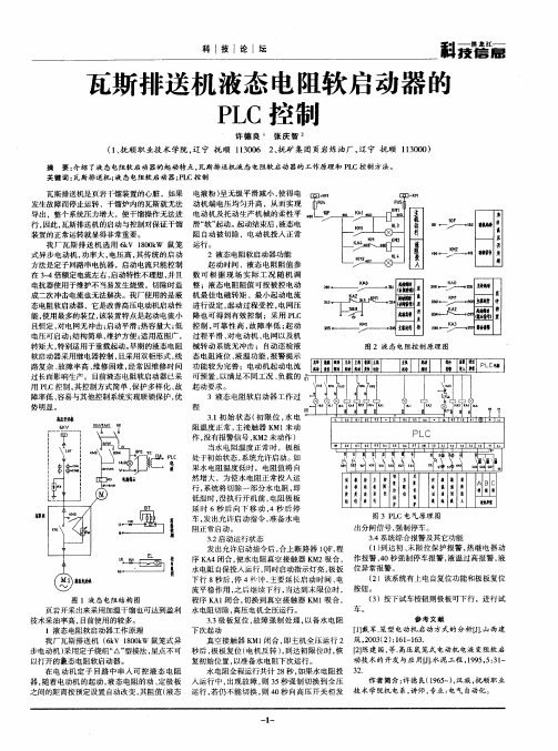
二,线路工作原理
2.1系统连接
参照电气原理图(以远控为例说明):接上远控按钮,合上隔离换相开关GHK,控制变压器KB1得电,控制与保护器QJ 及漏电闭锁组件K投入工作,若电源和负载都正常工作,即可开启启动器。
此时按下启动按钮,本安先导XD的固态继电器XJ1闭合,从而XJ2闭合,延时头继电器ZJ1和时间继电器SJ1\SJ2得电吸合,导线41与42通过ZJ1闭合而进入软启动状态,可控制按预先设定的模式结合现场条件,触发导通。
当软启动过程完毕后,切换触电闭合,中间继电器ZJ2 吸合,CJ吸合,旁路真空接触器投入运行,此时自保出点由ZJ1切换到CJ,整个启动过程完毕。
二、按键说明
三、菜单功能说明
七、指示灯说明
注:当A、V和%三个指示灯全灭时,当前显示内容为温度值。
软启动器出现故障时,RNU和STOP指示灯同时进行闪烁。
八、电气原件明细表。
GKY
液位控制西安祥天和电子商务有限公司专门从事液位控制的安装、维修服务二十多年,熟悉各类液位控制器的性能。
最早,我们使用传统的电极探头,价格很便宜,但用一段时间后,电极就会吸附很多杂质,寿命极短。
后来用UQK/GSK 干簧管,但水位波动,触点频繁吸合,使用寿命也短。
目前质量好一些的液位传感器可以用一年多,差的只能用几个月。
而现代微电子产品使用寿命可达十年以上,所以我们结合传统浮子和现代微电子技术研发了GKY 液位传感器,使用寿命长,三年内包换。
GKY 液位传感器也是目前唯一可以在污水中长期使用的传感器,欢迎登录本公司网站了解详情。
西安祥天和电子商务有限公司
(原名:西安祥和电子科技有限公司)
详情请咨询网站:。