Generator selection for offshore oscillating water column wave energy converters
- 格式:pdf
- 大小:483.69 KB
- 文档页数:8
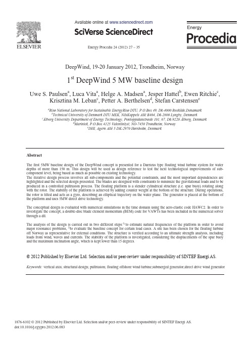
E nergy Procedia 24 ( 2012 )27 – 351876-6102 © 2012 Published by Elsevier Ltd. Selection and/or peer-review under responsibility of SINTEF Energi AS.doi: 10.1016/j.egypro.2012.06.083DeepWind, 19-20 January 2012, Trondheim, Norway1st DeepWind 5 MW baseline designUwe S. Paulsen a , Luca Vita a ,Helge A. Madsen a ,Jesper Hattel b ,Ewen Ritchie c ,Krisztina M. Leban c ,Petter A. Berthelsen d , Stefan Carstensen eaRisø National Laboratory for Sustainable EnergyRisø DTU,P.O.Box 49,Dk-4000 Roskilde,Denamarkb Technical University of Denmark DTU MEK,NilsKoppels AlléB404, Dk-2800 Lyngby, Denmarkc Ålborg University Department of Energy Technology, Pontoppidanstræde 101, 67, Dk-9220 Ålborg, Denmarkd Marintek, P.O.Box 4125 Valentinlyst, NO-7450 Trondheim, Norwaye DHI, Agern Allé 5 DK-2970 Hørsholm, Denmark AbstractThe first 5MW baseline design of the DeepWind concept is presented for a Darrieus type floating wind turbine system for water depths of more than 150 m. This design will be used as design reference to test the next technological improvements of sub-component level,being based as much as possible on existing technology.The iterative design process involves all sub-components and the potential constraints, and the most important dependencies are highlighted and the selected design presented. The blades are designed with constraints to minimize the gravitational loads and to be produced in a controlled pultrusion process. The floating platform is a slender cylindrical structure (i.e. spar buoy) rotating along with the rotor. The stability of the platform is achieved by adding counter weight at the bottom of the structure. During operations, the rotor is tilted and acts as a gyro, describing an elliptical trajectory on the water plane. The generator is placed at the bottom of the platform and uses 5MW direct drive technology.The conceptual design is evaluated with numerical simulations in the time domain using the aero-elastic code HAWC2. In order to investigate the concept, a double-disc blade element momentum (BEM) code for VAWTs has been included in the numerical solver through a dll.The analysis of the design is carried out in two different steps:1) to estimate natural frequencies of the platform in order to avoid major resonance problems,2)to evaluate the baseline concept for certain load cases. A site has been chosen for the floating turbine off Norway as representative for external conditions. The structure is verified according to an ultimate strength analysis, including loads from wind, waves and currents. The stability of the platform is investigated, considering the displacements of the spar buoy and the maximum inclination angle, which is kept lower than 15 degrees.©2011Published by Elsevier Ltd.Keywords: vertical axis; structural design; pultrusion; floating offshore wind turbine;submerged generator;direct drive wind generator Available online at © 2012 Published by Elsevier Ltd. Selection and/or peer-review under responsibility of SINTEF Energi AS.28U we S. Paulsen et al. / E nergy Procedia 24 ( 2012 )27 – 35 Figure 1:Constraints in developing baseline design[3]U we S. Paulsen et al. / E nergy Procedia 24 ( 2012 )27 – 35 29 1.2.Environmental loadsThe HAWC2 simulations take into account the important aero-elastic loads on the wind turbine andthe hydrodynamic loads due to the rotation of the platform in the water,i.e. Magnus effect, in-line forcesand friction torque. The estimation of these loads is based on results from literature [2, 5,6,7]. CFD calculations and physical model test with a rotating cylinder in combined waves and current are on-goingat DHI to verify the hydrodynamic loads and support their implementation in the HAWC2 model. Boththe numerical simulations and laboratory tests forecast a low friction loss, and a major Magnus force in combined waves and currents associated with the rotation.1.3.1st Design assumptionsThe post-stall as well as the effects by the wind turbulence are known to increase rotor loads in the dynamic stall region. The concept is described in 6-DOF:{(Pitch, Roll, Yaw), (Surge, Sway, Heave)}[1, 2]. The following assumptions are made in the first iteration design:x Atmospheric turbulence effects are not consideredx Dynamic stall is not includedx Evaluation of loads are conducted on a configuration with a limited DOF, i.e.Pitch, Roll,Yaw2.Rotor and blades design2.1.Site conditionsThe DeepWind design is site dependent [2, 3]. The H yWind test site has been selected as the representative site for the evaluation of DeepWind.The position is shown in Figure 2.For this site the environmental conditions are described by the NORSOK standard[8]as:Maximum 100 year tidal surface current in the order of 0.2m/s; wind induced (surface) current velocity of up to 0.5m/s;signify-Figure 2Approximate position of the DeepWind turbine evaluation site -here indicated with a red mark,from a map of the domainfor DHI’s North Sea wave hindcast model.30U we S. Paulsen et al. / E nergy Procedia 24 ( 2012 )27 – 35U we S. Paulsen et al. / E nergy Procedia 24 ( 2012 )27 – 35 31A number of changes are planned for the next iteration loop: a)a lower value of V improves the rotor stall characteristic and moves the rated conditions towards higher values of rotational speed and lower wind speed which results in a less costly generator, b)a thinner airfoil could improve the rotor stall characteristic. A VAWT reaches the power peak at a higher wind speed as compared to a HAWT and in order to provide a more reasonable comparison of the wind turbine concepts it is decided with DeepWindto obtain the same AEP of the 5 MW reference HAWT wind turbine,i.e.c)a rotor design with higher rated power is necessary. As in Figure 1 these changes affect the subcomponent level as well.2.2.Blade designThe use of pultrusion technology for VAWT blade manufacture is limited to constant chord over length; it provides a surplus in terms of low manufacturing cost but at the expense of increased material consumption to compensate for structural strength of relatively thin profiles. This has shown the necessityto design blades with structured ‘stiffeners’ which can avoid heavy blade design. The present blade design is not shape optimized to account for best rigidity at lowest blade weight in the first iteration of the process. Gravity and centrifugal load combinations are limiting design parameters and have impacts onthe rotor shape. A suitable alternative is to change the operating condition by changing the tip speed orrpm slightly-which changes the shape of the blade,and the loads as shown in Figure 4.The suggested design changes of the overall rotor will result in a lighter blade design. In particular it is structurally convenient to use thicker airfoils at positions which are nearer to the tower.Figure 4: Left: Two different blade shapes according to two different operational conditions. Right: Loads corresponding to the two different rotor shapes[3].The current blade span measures 189 m and weighs154 metric tons,which at this stage is too heavy with negative impacts on the systems design. Alternative blade designs such as using piecewise constant profiles, and thick profiles are explored at the moment.A compromise in the design includes a possible increase in the rated rotational speed,or a variation of the blade properties along the blade with lighterblade material density.32U we S. Paulsen et al. / E nergy Procedia 24 ( 2012 )27 – 353.Floating platformThe floating platform for the DeepWind concept is based on the spar technology. The spar concept has shown to be a promising solution for floating offshore wind turbines due to its favorable motion [9].The spar is a deep draught vertical cylinder with buoyancy chambers at the upper part and a heavier section at the lower end for stabilization. The upper part of the spar buoy is narrowed with a tapered section such that a small diameter is obtained in the wave zone, in order to limit wave loads and to connect the platform to the rotor tower. Vertical wave forces are minimized due to the deep draught of the spar buoy such that vertical motions are rather small. The low center of gravity provides large righting moment ensuring that the floater stays upright with low roll and pitch motion. The selection of the spar hull shape and size depends on functional requirements,and the following basic design requirements are considered:x Natural periods in heave and pitch/roll should be larger than the dominating wave periods(i.e. 5s-25 s)to avoid resonant motion responsex Sufficient buoyancy to carry specified payload and weight of the mooring systemx Sufficient vertical stiffness for variable vertical loadx Sufficient stiffness in roll and pitch to avoid excessive heeling of the platform due to environmental loadsx Acceleration should be limited to avoid damage to machinery componentsThe baseline design is summarized in Table 3.Table 3:Platform dimensionsGeometry of the platformTotal length (H P=H1+H2+H3)[m]108Depth of the slender part(H1)[m]5Radius of the slender part (R T)[m] 3.15Thickness of the slender part [m]0.02Length of the tapered part (H2)[m]10Length of the bottom part (H3)[m]93Maximum radius of the platform(R P)[m] 4.15Thickness of the bottom part[m]0.05The most relevant stiffness parameters of the platform were calculated in [3]to verify the design for fulfillment of the design requirements.Reduction of the top weight due to a re-design of the blades will alter the shape and size of the spar hull. A preliminary study indicates that reducing the blade mass and lowering the blades' mass centre allows for reducing the diameter and draught of the spar buoy. Further optimization of the spar design is therefore considered. In this context, optimization is the same as minimizing the material cost while satisfying the design requirements. The design iterations will also include finding a feasible mooring system that can withstand the large torque from the rotating wind turbine.U we S. Paulsen et al. / E nergy Procedia 24 ( 2012 )27 – 35 33 4.Subsea generator technology4.1.Generator State of the Art and Design IssuesA state of the art investigation was conducted to determine possible solutions for the generator. Typesof direct drive generators on the market were found and a comparison was made between the types of generator used in and proposed for wind power applications. Types of direct drive generators on the market are presented in Table 4:Table 4:Large Direct Drive Wind Turbines [10,11]Generator Type Power/Speed ManufacturerEESG 4.5 MW/ 13 rpm EnerconPMSG 3.5 MW/ 19 rpm ScanwindPMSG 2.5 MW/ 14.5(16) rpm VensysPMSG 2 MW/ 24 rpm MitsubishiPMSG 2 MW/ 18.5rpm STX WindpowerPMSG 2 MW/ 15.8 rpm EWT (Energya Wind Technologies)PMSG 2 MW/ 19 rpm JSW (Japan Steel Works)EESG 1.65 MW/ 20 rpm MT TorresPMSG 1.5 MW/ 23 rpm LeitwindPMSG 1.5MW/ 19 rpm GoldwindPMSG 1.5(2) MW/ 18(23) rpm ZephyrosPMSG0.75 MW/ 25 rpm Jeumont(not available)Siemens Wind Energy launched a 6MW direct drive SWT-6.0prototype in November 2010. The turbine is designed for the harsh offshore conditions. The first prototype was installed in May 2011 in Denmark. Offshore sites targeted for 2012-2013 include Denmark, UK, the Netherlands and Germany.Tests are still being carried out on the installed prototypes [12].Because of the special sub-sea ambient conditions, it is important to identify the best candidates for the DeepWind direct drive generator. This requires an assessment of the suitable candidates for the proposed application.During the project the following generator types were considered:1.SCIG-Squirrel Cage Induction Generator(Radial Flux RF)2.DFIG –Doubly Fed Induction Generator(Radial Flux RF)3.EESG -Electrically Excited Synchronous Generator(Radial Flux RF)4.PMSG -PM Synchronous Generator(Radial Flux RF)5.TFPM -Transverse Flux PM Generator6.AFPM –Axial Flux PM GeneratorA SWOT analysis was performed to narrow down the list of candidates.The main selection criteriawere related to the efficiency, torque/weight ratio, mass of active and inactive material, fault ride through capability, ease of manufacturing, existing turbines on the market. From this assessment and analysis itcan be concluded, that the candidates worth considering for the DeepWind direct drive applications are: Synchronous PM(PMSG)Synchronous Electrically Excited(EESG)Transverse Flux PM (TFPMG)34U we S. Paulsen et al. / E nergy Procedia 24 ( 2012 )27 – 35A design tool for each machine type tailored to direct drive specifications will be used to determinethe suitability of each generator type. The decision for proceeding with these machine types is related to the cost of permanent magnets and the particular optimization potential for each generator.4.2.DeepWind Generator Design approachThe analytic design algorithm for the machines was implemented in code language. Usual design rules used for power station generators were applied. It is anticipated that these will be adjusted to suit the subsea ambient conditions. The output of the analytic design will include the geometrical dimensions of the machine, mass of active and inactive materials and evaluation of losses. The geometrical dimensions obtained will be used as input for a finite element model to analyze and optimize the magnetic field distribution in the machine. For a given output, the diameter of the generator may be expected to be inversely proportional to the speed. As the direct drive turbine implies an extremely slow speed (see Table 4), the number of poles of the generator will increase. This means not only that the diameter of the machine will increase, but that the leakage field will also increase. This is not desired as it will reduce the efficiency of the generator. By observing the magnetic field in a particular machine design, suitable optimization measures can be taken in order to maximize the useful magnetic field and minimize the unwanted field effects.A thermal model of each candidate generator type will be constructed replicating the subsea ambient conditions and enabling the establishment of corresponding new appropriate design rules. This is because of the relatively unknown cooling conditions for the generator caused by the sub-sea environment and affected by the constructional details and enclosure. An optimization tool will be designed to improve the performance of the generator. By careful selection of the active materials and varying the geometry of the proposed design a new optimized machine design will be obtained. The output of the generator will be fed to a power electronic converter for conversion to voltage levels suitable for transmission to the local electricity utility grid. This will be a multi kilovolt connection, so a three level converter is anticipated. Control of the power flow will be by control of the shaft speed of the DeepWind turbine.4.3.First Iteration Dimensions of the 5 MW Direct Drive GeneratorThe first iteration of the 5 MW shaft input generator, based on the estimated rated speed of 5.26 rpm and the rated torque of 9.1MNm was for a 400 pole 17.53 Hz design with a pole pitch of around 7.85cm.This corresponds to an air-gap diameter of around 10 m outer diameter of around 10.5 m, with a core length of around 1.4 m. This will give a total mass of Copper, Iron and permanent magnet materials of around 90 metric tons. The dimensions fit very well with the estimated outer diameter of the platform which is 8.3 m, see Table 3, and will enable a reasonable construction.5.Design evaluationThe design was evaluated with the aero-elastic code HAWC2, in the configuration with 3DOF for the platform under conditions of the sea states[3]. The direction of the waves and the currents, with respect to the wind, was changed in order to evaluate the different loads from different combinations of wind, wave and current direction.Regarding the platform stability,the large inertia of the rotor affects the pitch and roll mode towards a large natural period. The simulations show a rotor inclination at the tower bottom less than 12ºwhen in combinations of wind and current relative to wind direction (waves -90ºand current co-parallel with wind directions, waves co-parallel and current -45º relative to wind directions)and an inclination less than6º in still water.The tower section at sea water level displaces for the most criticalU we S. Paulsen et al. / E nergy Procedia 24 ( 2012 )27 – 35 35 sea state with around 12 m along the wind direction and 12.5m to each side, compared to still water condition with 10.5m and 0.75m, respectively.The maximum loads were recorded at the point on the tower at the water level, and they occur at the most critical sea states (larger values of the wave height), while the mean values are strongly dependenton the currents direction[3].For the ultimate strength of the tower, a safety factor of 2 is used for maximum loads and 4 on mean loads.6.ConclusionsA 1st iteration conceptual 5 MW DeepWind baseline design for a Darrieus type floating wind turbine system with direct drive generator technology, for water depths of more than 150 m was carried out witha design evaluation of the concept. This design will be used as design reference to test the next technological improvements of sub-component level, being based as much as possible on existing technology. The results from the evaluation have shown that different issues in the design space are stillnot optimal and have to be iterated accordingly.AcknowledgementsThe work is a result of the contributions within the DeepWind project which is supported by the EuropeanCommission, Grant 256769 FP7 Energy 2010-Future emerging technologies, and by the DeepWind beneficiaries:DTU(DK), AAU(DK), TUDELFT(NL), TUTRENTO(I), D I(DK), SINTEF(N),MARINTEK(N), MARIN(NL), NREL(USA), STATOIL(N), VESTAS(DK) and NENUPHAR(F). References[1]Vita L, Paulsen US, Pedersen TF, Madsen HA, Rasmussen F A Novel Floating Offshore Windturbine Concept in Proceedingsof the European Wind Energy Conference (EWEC),Marseille, France,2009.[2]Vita L,Zhale F, Paulsen US Pedersen TF, Madsen HA, Rasmussen F. Novel Concept For Floating Offshore Wind Turbines:Concept Description And Investigation Of Lift, Drag And Friction Acting On The Rotating Foundation in Proceedings of the ASME 2010 29th International Conference on Ocean, Offshore and Arctic Engineering, June 6 Shanghai 2010 OMAE2010-20357.[3]Vita L Offshore floating vertical axis wind turbines with rotating platform Risø DTU, Roskilde, Denmark, PhD dissertationPhD 80, 2011.[4]Jonkman J, Butterfield S, Musial W, Scott G Definition of a 5-MW reference wind turbine for offshore system developmentNational Renewable Energy Laboratory, Golden, Colorado (US), Technical Report NREL/TP-500-38060, 2009.[5]Hoerner, SF,Borst HV Fluid-Dynamic Lift. Bricktown, NJ: Hoerner Fluid Dynamics, 1975.[6]Theodorse T, Kegier A Experiments on drag of revolving disks, cylinders, and streamline rods at high speeds, NationalAdvisory Committee for Aeronautics, Report no. 793.1945[7]Sumer BM, Fredsøe J Hydrodynamics around cylindrical structures, World Scientific, Advanced Series on Coastal Engineering–Volume 12. 1997[8]Norsok standard N-003 Ed.2 Actions And Action Effects2007.[9]H enderson AR,Witcher D, Floating Offshore Wind Energy -A Review of the Current Status and an Assessment of theProspects WIND ENGINEERING VOLUME 34, NO. 1, 2010 PP 01–16[10]Bang D, Polinder H, Shrestha G, Ferreira JA Review of Generator Systems for Direct-Drive Wind Turbines[11]Bang D Design of Transverse Flux PM M achines for Large Direct-Drive Wind Turbines.Busan,Korea:Master ofEngineering, Pukyong National University, 2010. ISBN 978-90-5335-336-3[12]/press/en/pressrelease/?press=/en/pressrelease/2011/wind-power/ewp201111014.htm.Site accessedDecember 18 2011.。

Safety Data Sheet Crafter’s Choice™ White Kaolin ClaySection 1: Identification of the Substance/Preparation and the Company Product Name : Crafter’s Choice™ White Kaolin Clay CAS Number: 1332-58-7 EC Number: 310-194-1 Applications Identified uses: Functional additive Details of the supplier of the safety data sheet: Crafter’s Choice Brands, LLC 7820 E. Pleasant Valley Road Independence, OH 44131 (800) 908-7028 Emergency telephone number: ChemTel (MIS3548100) (800) 255-3924 Domestic USA, Canada, Puerto Rico, USVI + (813) 248-0585 International Section 2: Hazards Identification Classification of the substance or mixture Classification according to Regulation (EC) 1272/2008 (EU 'CLP' regulation) Not classified as hazardous Classification according to Regulation (EC) No. 1272/2008[CLP] Not classified as hazardous. Classification according to Directive 67/5481EEC or 19991451EC Not classified as hazardous. Adverse physiochemical, human health and environmental effects Depending on the type of handling and use (e.g. grinding, drying), airborne respirable crystalline silica may be generated. Prolonged and/or massive Inhalation of respirable crystalline silica dust may cause lung fibrosis, commonly referred to as silicosis.Principal symptoms of silicosis are cough and breathlessness. Occupational exposure to respirable crystalline silica dust should be monitored and controlled. The product is not expected to be hazardous to the environment.Label elements Labelling according to Regulation (EC) 1272/2008 (EU 'CLP' regulation) Risk Phrases NC Not Classified Safety Phrases NC Not ClassifiedRevision Date: 09/25/2015Section 3: Composition and Information on IngredientsSubstancesSection 4: First-aid MeasuresDescription of first aid measuresGeneral advice No acute and delayed symptoms and effects are observed.Inhalation Move-into fresh air and keep at rest. Get medical attention if any discomfort continues.If swallowed Rinse mouth thoroughly. Get medical attention if any discomfort continues.Skin contact Wash skin with soap and water. Use suitable lotion to moisturize skin.Eye contact Do not rub eye. Rinse with large quantities of water. Get medical attention if irritation persists.Most important symptoms and effects, both acute and delayedGeneral informationIf adverse symptoms develop as described, transfer the casualty to a hospital as soon as possible.Indication of any immediate medical attention and special treatment neededNo specific first aid measures noted.Section 5: Fire-fighting MeasuresExtinguishing mediaThis product is non-combustible. No specific extinguishing media is needed.Special hazards arising from the substances or mixtureNon-combustible. No hazardous thermal decomposition.Advice for fire-fightersNo specific fire-fighting protection is required. Use an extinguishing agent suitable for the surrounding fire. Section 6: Accidental Release MeasuresPersonal precautions, protective equipment and emergency proceduresGeneral measuresAvoid airborne dust generation. Wear personal protective equipment incompliance with national legislation.Avoid dry sweeping and use water spraying or vacuum cleaning systems to prevent airborne dust generation. Wear personal protective equipment in compliance with national legislation.Reference to any other sectionsFor personal protection, see section 8. For waste disposal, see section 13.Section 7: Handling and StoragePrecautions for safe handlingAvoid airborne dust generation. Provide appropriate exhaust ventilation at places where airborne dust is generated. In case of insufficient ventilation, wear suitable respiratory protective equipment. Handle packaged products carefully to prevent accidental bursting. If you require advice on safe handling techniques, please contact your supplier or check the Good Practice Guide referred to in section 16. Do not to eat, drink and smoke in work areas; wash hands after use; remove contaminated clothing and protective equipment before entering eating areas.Conditions for safe storage, including any incompatibilitiesStore in a dry covered area. Minimize airborne dust generation and prevent wind dispersal during loading and unloading. Keep containers closed and store packaged products so as to prevent accidental bursting.Specific end use(s)Usage DescriptionIf you require advice on specific uses, please contact your supplier or check the Good Practice Guide referred to in section 16.Section 8: Exposure Controls/Personal ProtectionControl parametersExposure controlsEngineering measuresMinimize airborne dust generation. Use process enclosures, local exhaust ventilation or other engineering controls lo keep airborne levels below specified exposure limits. If user operations generate dust, fumes or mist, use ventilation to keep exposure lo airborne particles below the exposure limit. Apply organizational measures, e.g. by isolating personnel from dusty areas. Remove end wash soiled clothing.Respiratory equipmentIn case of prolonged exposure to airborne dust concentrations, wear a respiratory protective equipment that complies with the requirements of European or national legislation.Use eye protection. Goggles/face shield are recommended. Contact lenses should not be worn when working with this product.Hygiene measuresWhen using, do not eat, drink or smoke. Wash hands at the end of each work shift and before eating, smoking and using the toilet.Use appropriate skin cream to prevent drying of skin.Skin protectionNo specific requirement. Appropriate protection (e.g. protective clothing, barrier cream) is recommended for workers who suffer from dermatitis or sensitive skin.Section 9: Physical and Chemical PropertiesInformation on basic physical and chemical propertiesAppearance LumpColor White / Off-whiteOdor Almost odorlessSolubility Insoluble in waterRelative density 2.6 – 2.7Other InformationNo information requiredSection 10: Stability and ReactivityReactivityNo specific reactivity hazards associated with this product.Chemical stabilityStable under normal temperature conditions and recommended use.Possibility of hazardous reactionsNot applicable.Conditions to avoidNo particular incompatibilityIncompatible materialsNo specific, or groups of materials are likely to react to produce a hazardous situation.Hazardous decomposition productsNone under normal conditions.Section 11: Toxicological InformationInformation on toxicological effectsAcute toxicity This product has low toxicity. Only large volumes may haveadverse impact on human health.Skin corrosion / irritation Prolonged contact may cause dryness of skinSerious eye damage / eye irritation Particles in the eyes may cause inflammation and smarting Respiratory or skin sensitization Dust in high concentrations may irritate the respiratory system Germ cell mutagenicity Not classifiedCarcinogenicity Not classifiedReproductive toxicity Not classifiedSpecific target organ toxicity – single exposure Not classifiedSpecific target organ toxicity – repeated exposure Not classifiedAspiration hazard Not classifiedSection 12: Ecological InformationToxicityLC 50, 96 Hrs. Fish mg/l >1000EC 50, 48 Hrs. Daphnia, mg/l >1000IC 50, 72 Hrs. Algae, mg/l >1000Persistence and biodegradabilityThe product is not biodegradable.Bio-accumulative potentialThe product does not contain any substances expected to be bio-accumulating.Mobility in soilThe product is insoluble in water.Results of PBT and vPvB assessmentNot Classified as PBT/vPvB by current EU criteriaOther adverse effectsEcotoxicityThe product components are not classified as environmentally hazardous. However, this does not exclude the possibility that large or frequent spills can have a harmful or damaging effect on the environment.Section 13: Waste Disposal InformationGeneral InformationThis mineral can be disposed of as a nontoxic/inactive material in approved landfill sites in accordance with local regulations. Dust formation from residues in packaging should be avoided and suitable worker protection assured. Store used packaging in enclosed receptacles. Recycling and disposal of packaging should be carried out in compliance with local regulations. The re-use of packaging is not recommended. Recycling and disposal of packaging should be carried out by an authorized waste management company.Waste treatment methodsWhere possible, recycling is preferable to disposal. Can be disposed of in compliance with local regulations.Section 14: Transport InformationUN NumberNo information requiredTransport hazard class(es)No information required.Packaging groupNo information required.Environmental hazardsEnvironmentally Hazardous Substance / Marine Pollutant - No.Special precautions for userNot applicableTransport In bulk according to Annex U of MARPOL 73178 and IBC CodeNo Information required.Section 15: Regulatory InformationSafety, health and environmental regulations/legislation specific for the substance or mixtureUK Regulatory ReferencesHealth and Safety at Work Act 1974. The Control of Substances Hazardous to Health Regulations 2002 (S.I 2002 No. 2677) with amendments.Statutory InstrumentsThe Chemicals (Hazard Information and Packaging for Supply) Regulations 2009 (S.I 2009 No. 716).Approved Code of PracticeSafety Data Sheets for Substances and Preparations. Classification and Labelling of Substances and Preparations Dangerous for Supply.EU-RegulationsExempted in accordance with Annex V.7National regulationsWorkplace exposure Limits 2005 (EH40)Water hazard classificationNWGChemical safety assessmentNo chemical safety assessment has been carried out.Section 16: Additional InformationGeneral informationWorkers must be informed of the presence of crystalline silica and trained in the proper use and handling of this product as required under applicable regulations.A multi-sectoral social dialogue agreement on Workers Health Protection through the Good Handling and Use of Crystalline Silica and Products Containing It was signed on 25 April 2006. This autonomous agreement, which receives the European Commission’s financial support, is based on a Good Practices Guide. The requirements of the Agreement camehttp://www.nepsi.eu and provide useful Information and guidance for the handling of products containing respirable crystalline silica. Literature references are available on request from EUROSIL, the European Association of Industrial Silica Producers.Prolonged and/or massive exposure to respirable crystalline silica-containing dust may cause silicosis, a nodular pulmonary fibrosis caused by deposition in the lungs of fine respirable particles of crystalline silica.In 1997, IARC (the International Agency for Research on Cancer) concluded that crystalline silica inhaled from occupational sources can cause lung cancer in humans. However it pointed out that not all industrial circumstances, nor all crystalline silica types were to be incriminated. (IARC Monographs on the evaluation of the carcinogenic risks of chemicals to humans, Silica, silicates dust and organic fibers, 1997, Vol. 68, IARC, Lyon, France.)In June 2003, SCOEL (the EU Scientific Committee on Occupational Exposure Limits) concluded that the main effect in humans of the inhalation of respirable crystalline silica dust is silicosis. "There is sufficient information to conclude that the relative risk of lung cancer is increased in persons with silicosis (and, apparently, not in employees without silicosis exposed to silica dust in quarries and in the ceramic industry. Therefore preventing the onset of silicosis will also reduce the cancer risk…” (SCOEL SUM Doc 94 - final, June 2003).So there is a body of evidence supporting the fact that increased cancer risk would be limited to people already suffering from silicosis. Worker protection against silicosis should be assured by respecting the existing regulatory occupational exposure limits and Implementing additional risk management measures where required.Health & Safety Executive: Detailed reviews of the scientific evidence on the health effects or crystalline silica have been published by HSE (Health and Safety Executive, UK) in the Hazard Assessment Documents EH75/4 (2002) and EH75/5 (2003). The HSE points out on its website that Workers exposed to fine dust containing quartz are at risk of developing a chronic and possibly severely disabling lung disease known as "silicosis”. In addition to silicosis, there is now evidence that heavy and prolonged workplace exposure, to dust containing crystalline silica can lead to an increased risk of lung cancer. The evidence suggests that an increased risk of lung cancer is likely to occur only in those workers who have developed silicosis.Disclaimer: The Information in this Safety Advisory Document was obtained from sources which we believe are reliable, but no warranty or representation as to its accuracy or completeness is hereby given. Users should consider the information herein only as a supplement to other information gathered by them and must make independent determinations of suitability and completeness of information from all sources to assure proper use and disposal the safety and health of employees and customers and the protection of the environment.。

浙江大学学报(农业与生命科学版)48(4):483~492,2022Journal of Zhejiang University (Agric.&Life Sci.)http :///agr E -mail :zdxbnsb @沙棘果渣还田对水稻土性质、温室气体排放和微生物数量的影响万清1,杨小渔1,吴丹2,张奇春1*(1.浙江大学环境与资源学院,污染环境修复与生态健康教育部重点实验室,杭州310058;2.浙江大学生物系统工程与食品科学学院,杭州310058)摘要采用28d 的土壤培养试验,选用沙棘果渣(R )、生物质炭(B )和生物陶粒(T )3组材料,以自然培养组作为对照(CK ),探讨沙棘果渣对土壤理化性质、温室气体(CO 2、CH 4和N 2O )排放和微生物数量等方面的影响。
结果表明:沙棘果渣能够显著提升土壤中全碳、全氮、速效钾等养分的含量,平均提升率分别为16.31%、14.99%、46.15%;对土壤pH 也存在一定的提升效果,提升范围为0.25~0.69。
沙棘果渣还田后土壤微生物丰度显著升高,其中前14d 微生物数量较对照平均增长335.6%。
对不同材料还田后的温室气体排放和全球增温潜势分析表明,与生物质炭和生物陶粒相比,沙棘果渣还田的CO 2排放量和全球增温潜势显著较高,但其CH 4排放量较小且可以显著降低N 2O 的排放量。
总体来看,沙棘果渣具有较高的还田价值,但需要考虑对温室气体排放的风险,本研究可为沙棘果渣的农业还田利用提供一定参考。
关键词沙棘果渣;生物质炭;生物陶粒;微生物数量;温室气体;土壤理化性质中图分类号X 172文献标志码A引用格式万清,杨小渔,吴丹,等.沙棘果渣还田对水稻土性质、温室气体排放和微生物数量的影响[J].浙江大学学报(农业与生命科学版),2022,48(4):483-492.DOI:10.3785/j.issn.1008-9209.2021.06.291WAN Qing,YANG Xiaoyu,WU Dan,et al.Effects of returning seabuckthorn fruit residue into field on paddy soil properties,greenhouse gas emissions and microbial numbers[J].Journal of Zhejiang University (Agriculture &Life Sciences),2022,48(4):483-492.Effects of returning seabuckthorn fruit residue into field on paddy soilproperties,greenhouse gas emissions and microbial numbersWAN Qing 1,YANG Xiaoyu 1,WU Dan 2,ZHANG Qichun 1*(1.Ministry of Education Key Laboratory of Environmental Remediation and Ecological Health,College of Environmental and Resource Sciences,Zhejiang University,Hangzhou 310058,China;2.College of Biosystems Engineering and Food Science,Zhejiang University,Hangzhou 310058,China )AbstractTo explore the effects of seabuckthorn fruit residue on soil physicochemical properties,greenhousegas (CO 2,CH 4,N 2O)emissions,and the microbial numbers,a 28-day soil pot experiment was conducted.Three groups of materials were used,including seabuckthorn fruit residue (R),biochar (B),and biological ceramsite (T)in the experiment,and a natural culture was used as the control group (CK).The results showed that the seabuckthorn fruit residue significantly promoted the contents of soil nutrients such as total carbon,total nitrogen,and available potassium,and the average increase rates were 16.31%,14.99%,and 46.15%,respectively.Besides,the soil pHDOI :10.3785/j.issn.1008-9209.2021.06.291基金项目:国家重点研发计划课题(2021YFD1700803);浙江省重点研发计划项目(2021C04032)。

AMETEK880NSL硫比值分析仪在海南炼化硫磺回收装置应用总结摘要:本文简要的介绍了AMETEK880NSL型硫比值分析仪的工作原理和系统构成,结合其在海南炼化硫磺回收装置的运行经验,对其运行状况、常见故障及处理方法和使用过程发现的缺陷进行了总结。
关键词:硫比值分析仪运行状况常见故障应用总结装置简介:海南炼化硫磺回收装置设计负荷为生产硫磺8万吨/年,年开工时间为8400小时,操作弹性范围是30-110%,硫回收率99.8%,尾气净化度达到小于960mg/m3。
本装置由SEI总承包,山东三维石化工程股份有限公司负责基础设计和工程设计,中石化第二建设公司承建。
硫磺装置由Claus制硫系统、尾气处理系统、尾气焚烧系统、液硫脱气系统组成。
装置采用中石化自主开发SSR无在线炉硫回收工艺,采用二头一尾配置。
装置原料是溶剂再生装置来清洁酸性气和酸性水汽提装置来含氨酸性气。
本装置于2006年9月首次开车成功,最长运行周期为39个月。
制硫炉配风采用双回路控制系统,即大配风与酸性气流量采用比例控制,小配风与硫比值分析仪计算的需氧量串级控制。
一、概述在克劳斯硫磺回收工艺中,通常采用硫化氢/二氧化硫比值分析仪对制硫尾气中的H2S与SO2浓度进行分析,参与制硫炉酸性气/空气配比控制,精确控制制硫炉的配风量,提高制硫装置硫回收率,同时防止尾气部分发生SO2穿透,因此提高硫比值分析仪的精确度、缩短分析时间和降低故障率,对于硫磺回收及尾气处理装置的操作至关重要。
本装置采用了AMETEK880NSL型硫比值分析仪,为了提高比值仪分析的准确性,将比值仪安装在制硫装置尾气分液罐出口水平段管线上,此段位置介质具有压力稳定、流速均匀的特点,同时为了缩短比值仪采样时间,降低分析结果的滞后性,将比值仪整体设备直接安装在管道上,尽量降低采样管长度。
AMETEK880NSL型硫比值分析仪具有自动化程度高的特点,分析仪控制系统自动执行所有的正常运行步骤,包括启动样品流动、分析、在线校准、量程选择、错误检测、区域温度控制及出错自动反吹等步骤,维护人员可由设备自带显示屏得知设备的运行状态和错误信息。

Series OGZ Pneumatic Miniature Parallel Gripper• Available in 4 sizes• Integral linear guide for high rigidity and precision • Base dowel mounting for accurate locating • S tandard magnets on pistons for externally mounted switches • Drop-in replacement for other manufacturersThe Price AlternativeOGZ01(800) 624-85112(800) 624-8511/ogzOGZ01© Copyright 2019, by PHD, Inc. All Rights Reserved. Printed in the U.S.A.MODEL NO.OGZ D 1 5SWITCH BUNDLE DESIGN NO.5 = Metric-x SIZEMINIMUM TOTAL JAW TRAVEL SIZE 10162025D = DC ReedN = DC Solid State NPN - Sink P = DC Solid State PNP - SourceTYPED = DOUBLE ACTING, STANDARD STROKEJAW STYLE 1 = STANDARD TAPPED HOLENOTES:1) Switch bundle option includes 2 switches 2) Switch bundle available with actuator only 3) Switches available in quick connect only 4) Magnets standard for switch sensing 5) Only use PHD’s switches with actuator3(800) 624-8511/ogzOGZ01standard mountingpatterns and thread sizesintegral linear guide for high rigidity and precisionstandard magnet on piston for externally mounted switches• Available in 4 sizes• Integral linear guide for high rigidity and precision • Base dowel mounting for accurate locating• S tandard magnets on pistons for externally mounted switches • Drop-in replacement for other manufacturers4(800) 624-8511/ogzOGZ01Operating Pressure = 5 bar , Grip Length = 20 mmExternal GripInternal Grip5(800) 624-8511/ogzOGZ016(800) 624-8511/ogzOGZ01External GripInternal GripThe grip force F is shown in the graphs to the right and represents the force of one jaw with the workpiece in contact with both jaws and attachments. The total grip force is two times the grip force per jaw.4[0.9]8[1.8]12[2.7]16[3.6]20[0.8]40[1.6]60[2.4]20[0.8]40[1.6]60[2.4]20[0.8]40[1.6]60[2.4]20[0.8]40[1.6]60[2.4]Grip Length L (mm [in])G r i pF o r c e F (N [l b f ])010[2.2]20[4.5]30[6.7]40[9.0]50[11.2]Grip Length L (mm [in])OGZD15-16x6 External GripG r i p F o r c e F (N [l b f ])20[0.8]40[1.6]60[2.4]80[3.1]100[3.9]20[0.8]40[1.6]60[2.4]80[3.1]100[3.9]Grip Length L (mm [in])OGZD15-20x10 External GripG r i p F o r c e F (N [l b f ])20[0.8]40[1.6]60[2.4]80[3.1]100[3.9]120[4.7]20[0.8]40[1.6]60[2.4]80[3.1]100[3.9]120[4.7]Grip Length L (mm [in])OGZD15-25x14 External GripG r i p F o r c e F (N [l b f ])40[9.0]80[18.0]120[27.0]160[36.0]Grip Length L (mm [in])OGZD15-25x14 Internal GripG r i p F o r c e F (N [l b f ])020[4.5]40[9.0]60[13.5]80[18.0]100[22.5]020[4.5]40[9.0]60[13.5]80[18.0]100[22.5]Grip Length L (mm [in])OGZD15-20x10 Internal GripG r i p F o r c e F (N [l b f ])10[2.2]20[4.5]30[6.7]40[9.0]50[11.2]60[13.5]70[15.7]10[2.2]20[4.5]30[6.7]40[9.0]50[11.2]60[13.5]70[15.7]Grip Length L (mm [in])OGZD15-16x6 Internal GripG r i p F o r c e F (N [l b f ])05[1.1]10[2.2]15[3.4]20[4.5]25[5.6]30[6.7]Grip Length L (mm [in])G r i p F o r c e F (N [l b f ])at 7 bar [101.5 psi]at 6 bar [87.0 psi]at 5 bar [72.5 psi]at 4 bar [58.0 psi]at 3 bar [43.5 psi]at 2 bar [29.0 psi]7(800) 624-8511/ogzOGZ01The grip length L and grip offset H must stay within the range for the operating pressure as shown in the graphs to the right. If the grip point exceeds the range limits, the life of the gripper will be reduced.External GripInternal Grip10[0.4]20[0.8]30[1.2]40[1.6]50[2.0]60[2.4]010[0.4]20[0.8]30[1.2]40[1.6]50[2.0]60[2.4]010[0.4]20[0.8]30[1.2]40[1.6]50[2.0]60[2.4]20[0.8]10[0.4]30[1.2]50[2.0]40[1.6]60[2.4]20[0.8]10[0.4]30[1.2]50[2.0]40[1.6]60[2.4]20[0.8]10[0.4]30[1.2]50[2.0]40[1.6]60[2.4]Grip Length L (mm [in])G r i p O f f s e t H (m m [i n ])10[0.4]20[0.8]30[1.2]40[1.6]50[2.0]60[2.4]70[2.8]Grip Length L (mm [in])OGZD15-16x6 External GripG r i p O f f s e t H (m m [i n ])20[0.8]40[1.6]60[2.4]80[3.1]100[3.9]020[0.8]40[1.6]60[2.4]80[3.1]100[3.9]40[1.6]20[0.8]60[2.4]100[3.9]80[3.1]40[1.6]20[0.8]60[2.4]100[3.9]80[3.1]Grip Length L (mm [in])OGZD15-20x10 External GripG r i p O f f s e t H (m m [i n ])020[0.8]40[1.6]60[2.4]80[3.1]100[3.9]120[4.7]020[0.8]40[1.6]60[2.4]80[3.1]100[3.9]120[4.7]40[1.6]20[0.8]60[2.4]100[3.9]120[4.7]80[3.1]Grip Length L (mm [in])OGZD15-25x14 External GripG r i p O f f s e t H (m m [i n ])Grip Length L (mm [in])OGZD15-25x14 Internal GripG r i p O f f s e t H (m m [i n ])40[1.6]20[0.8]60[2.4]80[3.1]Grip Length L (mm [in])OGZD15-20x10 Internal GripG r i p O f f s e t H (m m [i n ])Grip Length L (mm [in])OGZD15-16x6 Internal GripG r i p O f f s e t H (m m [i n ])20[0.8]10[0.4]30[1.2]50[2.0]40[1.6]Grip Length L (mm [in])G r i p O f f s e t H (m m [i n ])at 6 bar [87.0 psi]at 7 bar [101.5 psi]at 6 & 7 bar at 5 bar [72.5 psi]at 4 bar [58.0 psi]at 3 bar [43.5 psi]at 2 bar [29.0 psi]8NOTES:1) Dimensions are in mm2) Designated centerline is centerline of unit 3) Unless otherwise dimensioned,mounting hole patterns are centered on designated centerline of unitALL DIMENSIONS ARE REFERENCE ONLY UNLESS SPECIFICALLY TOLERANCED.。

Breeze 2安装和配置指南715001951_ZH/修订版 B版权所有 © Waters Corporation 2008−2009保留所有权利ii版权声明© 2008−2009 WATERS CORPORATION 。
在美国和爱尔兰印刷。
保留所有权利。
未经出版商的书面允许,不得以任何形式转载本文档或其中的任何部分。
本文档中的信息如有更改,恕不另行通知,且这些信息并不作为 Waters Corporation 的承诺。
Waters Corporation 对本文档中可能出现的任何错误不负任何责任。
本文档在出版时被认为是完整和准确的。
任何情况下,对与使用本文档有关或因使用本文档而导致的偶发或继发的损害,Waters Corporation 不负任何责任。
商标Waters 是 Waters Corporation 的注册商标,Breeze 、busLAC/E 、busSAT/IN 和“THE SCIENCE OF WHAT'S POSSIBLE.”是 Waters Corporation 的商标。
Adobe 、Acrobat 和 Reader 是 Adobe Systems Incorporated 在美国和/或其他国家/地区的注册商标。
Intel 和 Pentium 是 Intel Corporation 的注册商标。
Microsoft 、Internet Explorer 、Windows 和 Windows Vista 是 Microsoft Corporation 在美国和/或其他国家/地区的注册商标。
Oracle 是 Oracle Corporation 和/或其附属公司的注册商标。
Rheodyne 是 Rheodyne, Inc. 的注册商标。
其它注册商标或商标均为其各自所有者的专有资产。
客户意见或建议Waters 的技术交流部门恳请您告诉我们您在该文档中所遇到的任何错误或向我们提出改进建议。
测井资料常用英文代码表Microlog 1 Microlog 2 Acousticlog Density Compensated Dual-Spacing Neutron Log Caliper Bit Size Gamma Ray-Natural Radioactivity Spontaneous Potential Deep Investigation Induction Log Midium Investigation Induction Log Laterolog 8 Micro-Sphericlly Focused Log Laterolog Deep Laterolog Shallow Resistivity 4True Formation ResistivityResistivity 2.5 中子伽马 中子伽马 泥质含量 孔隙度 渗透率 含水饱和度 含油饱和度 束缚水饱和度 残余油饱和度 深侧向电阻率 LLD 浅侧向电阻率 LLS 4米梯度电阻率RT 地层真电阻率RT 感应电导率2.5 米梯 度电 阻率 R2.5 微梯度ML1 微电位ML2 声波时差AC 密度DEN 中子孔隙度CNL 井径CAL 钻头大小BS 自然伽马GR 自然电位SP 深感应电阻率ILD 中感应电阻率ILM 八侧向电阻率LL8 COND Conductivity NGR Neutron Gamma RaySH ShalePOR PorosityPERM PermeabilitySW Water SaturationSO Oil Saturation ofSWI Initial Water SaturationSOR Residual Oil Saturation微 球 形 聚 焦 电 阻 率 MSFL NEU Neutron斯仑贝谢 ( Schlumberger ) 常用英文缩写数控测井系统CSU Cyber Service Units 或Computerized Logging Units 声波时差DT Delta T密度RHOB Rho Bulk中子孔隙度NPHI Neutron Phi感应电导率CILD IL-Deep Conductivity井径CALS Caliper Size自然伽马能谱NGS Natural Gamma Ray Spectrolog铀URAN Uranium钍THOR Thorium钾POTA Potassium高分辨率地层倾角仪HDT High Resolution Dipmeter Tool地层学高分辨率地层倾角仪SHDT Stratigraphy High Resolution Dipmeter Tool地层压力RFT Repeat Formation Tester波形WF Wave Form微电阻率成像FMI Fullbore Formation Micro Imager Tool 阵列感应成像AIT Array Induction Imager Tool方位侧向成像ARI Azimuthal Resistivity Imager Tool偶极声波成像DSI Dipole Shear Sonic Image Tool超声波成像USI Ultrasonic Imager Tool核磁共振CMR Combination Magnetic Resonance模块式地层动态测试仪MDT Modular Formation Dynamics Tester测井曲线名称汇总GRSL—能谱自然伽马POR 孔隙度NEWSANDPORW 含水孔隙度NEWSANDPORF 冲洗带含水孔隙度NEWSANDPORT 总孔隙度NEWSANDPORX 流体孔隙度NEWSANDPORH 油气重量NEWSANDBULK 出砂指数NEWSANDPERM 渗透率NEWSANDSW 含水饱和度NEWSANDSH 泥质含量NEWSANDCALO 井径差值NEWSANDCL 粘土含量NEWSANDDHY 残余烃密度NEWSANDSXO 冲洗带含水饱和度NEWSANDDA 第一判别向量的判别函数NEWSAND DB 第二判别向量的判别函数NEWSAND DAB 综合判别函数NEWSANDCI 煤层标志NEWSANDCARB 煤的含量NEWSANDTEMP 地层温度NEWSANDQ 评价泥质砂岩油气层产能的参数NEWSANDPI 评价泥质砂岩油气层产能的参数NEWSAND SH 泥质体积CLASSSW 总含水饱和度CLASSPOR 有效孔隙度CLASSPORG 气指数CLASSCHR 阳离子交换能力与含氢量的比值CLASS CL 粘土体积CLASSPORW 含水孔隙度CLASSPORF 冲洗带饱含泥浆孔隙度CLASSCALC 井径差值CLASSDHYC 烃密度CLASSPERM 绝对渗透率CLASSPIH 油气有效渗透率CLASSPIW 水的有效渗透率CLASSCLD 分散粘土体积CLASSCLL 层状粘土体积CLASSCLS 结构粘土体积CLASSEPOR 有效孔隙度CLASSESW 有效含水饱和度CLASSTPI 钍钾乘积指数CLASSPOTV 10 0%粘土中钾的体积CLASSCEC 阳离子交换能力CLASSQV 阳离子交换容量CLASSBW 粘土中的束缚水含量CLASSEPRW 含水有效孔隙度CLASSUPOR 总孔隙度,UPOR=EPOR+BW CLASS HI 干粘土骨架的含氢指数CLASSBWCL 粘土束缚水含量CLASSTMON 蒙脱石含量CLASSTILL 伊利石含量CLASSTCHK 绿泥石和高岭石含量CLASSVSH 泥质体积CLASSVSW 总含水饱和度CLASSVPOR 有效孔隙度CLASSVPOG 气指数CLASSVCHR 阳离子交换能力与含氢量的比值CLASS VCL 粘土体积CLASSVPOW 含水孔隙度CLASSVPOF 冲洗带饱含泥浆孔隙度CLASSVCAC 井径差值CLASSVDHY 烃密度CLASSVPEM 绝对渗透率CLASSVPIH 油气有效渗透率CLASSVPIW 水的有效渗透率CLASSVCLD 分散粘土体积CLASSVCLL 层状粘土体积CLASSVCLS 结构粘土体积CLASSVEPO 有效孔隙度CLASSVESW 有效含水饱和度CLASSVTPI 钍钾乘积指数CLASSVPOV 100%粘土中钾的体积CLASSVCEC 阳离子交换能力CLASSVQV 阳离子交换容量CLASSVBW 粘土中的束缚水含量CLASSVEPR 含水有效孔隙度CLASSVUPO 总孔隙度CLASSVHI 干粘土骨架的含氢指数CLASSVBWC 粘土束缚水含量CLASSVTMO 蒙脱石含量CLASSVTIL 伊利石含量CLASSVTCH 绿泥石和高岭石含量CLASSQW 井筒水流量PLIQT 井筒总流量PLISK 射孔井段PLIPQW 单层产水量PLIPQT 单层产液量PLIWEQ 相对吸水量ZRPM PEQ 相对吸水强度ZRPM POR 孔隙度PRCO PORW 含水孔隙度PRCO PORF 冲洗带含水孔隙度PRCO PORT 总孔隙度PRCO PORX 流体孔隙度PRCO PORH 油气重量PRCO BULK 出砂指数PRCO HF 累计烃米数PRCO PF 累计孔隙米数PRCO PERM 渗透率PRCO SW 含水饱和度PRCO SH 泥质含量PRCO CALO 井径差值PRCO CL 粘土含量PRCO DHY 残余烃密度PRCO SXO 冲洗带含水饱和度PRCO SWIR 束缚水饱和度PRCO PERW 水的有效渗透率PRCOPERO 油的有效渗透率PRCOKRW 水的相对渗透率PRCOKRO 油的相对渗透率PRCOFW 产水率PRCOSHSI 泥质与粉砂含量PRCOSXOF 199*SXO PRCOSWCO 含水饱和度PRCOWCI 产水率PRCOWOR 水油比PRCOCCCO经过PORT校正后的C/ O值PRCOCCSC经过PORT校正后的SI/CA值PRCOCCCS经过PORT校正后的CA/SI值PRCODCO油水层C/ O差值PRCOXIWA 水线视截距PRCOCOWA 视水线值PRCOCONM 视油线值PRCOCPRW 产水率(C/ O计算)PRCOCOAL 煤层CRAOTHR 重矿物的百分比含量CRASALT 盐岩的百分比含量CRASAND 砂岩的百分比含量CRALIME 石灰岩的百分比含量CRADOLM 白云岩的百分比含量CRAANHY 硬石膏的百分比含量CRA ANDE 安山岩的百分比含量CRA BASD 中性侵入岩百分比含量CRA DIAB 辉长岩的百分比含量CRA CONG 角砾岩的百分比含量CRA TUFF 凝灰岩的百分比含量CRA GRAV 中砾岩的百分比含量CRA BASA 玄武岩的百分比含量CRA常用测井曲线名称A1R1 T1R1 声波幅度A1R2 T1R2 声波幅度A2R1 T2R1 声波幅度A2R2 T2R2 声波幅度AAC 声波附加值AAVG 第一扇区平均值AC 声波时差AF10 阵列感应电阻率AF20 阵列感应电阻率AF30 阵列感应电阻率AF60 阵列感应电阻率AF90 阵列感应电阻率AFRT 阵列感应电阻率AFRX 阵列感应电阻率AIMP 声阻抗AIPD 密度孔隙度AIPN 中子孔隙度AMAV 声幅AMAX 最大声幅AMIN 最小声幅AMP1 第一扇区的声幅值AMP2 第二扇区的声幅值AMP3 第三扇区的声幅值AMP4 第四扇区的声幅值AMP5 第五扇区的声幅值AMP6 第六扇区的声幅值AMVG 平均声幅AO10 阵列感应电阻率AO20 阵列感应电阻率AO30 阵列感应电阻率AO60 阵列感应电阻率AO90 阵列感应电阻率AOFF 截止值AORT 阵列感应电阻率AORX 阵列感应电阻率APLC 补偿中子AR10 方位电阻率AR11 方位电阻率AR12 方位电阻率ARO1 方位电阻率ARO2 方位电阻率ARO3 方位电阻率ARO4 方位电阻率ARO5 方位电阻率ARO6 方位电阻率ARO7 方位电阻率ARO8 方位电阻率ARO9 方位电阻率AT10 阵列感应电阻率AT20 阵列感应电阻率AT30 阵列感应电阻率AT60 阵列感应电阻率AT90 阵列感应电阻率ATAV 平均衰减率ATC1 声波衰减率ATC2 声波衰减率ATC3 声波衰减率ATC4 声波衰减率ATC5 声波衰减率ATC6 声波衰减率ATMN 最小衰减率ATRT 阵列感应电阻率ATRX 阵列感应电阻率AZ 1 号极板方位AZ1 1 号极板方位AZI 1 号极板方位AZIM 井斜方位BGF 远探头背景计数率BGN 近探头背景计数率BHTA 声波传播时间数据BHTT 声波幅度数据BLKC 块数BS 钻头直径BTNS 极板原始数据C1 井径C2 井径C3 井径CAL 井径CAL1 井径CAL2 井径CALI 井径CALS 井径CASI 钙硅比CBL 声波幅度CCL 磁性定位CEMC 水泥图CGR 自然伽马CI 总能谱比CMFF 核磁共振自由流体体积CMRP 核磁共振有效孔隙度CN 补偿中子CNL 补偿中子CO 碳氧比CON1 感应电导率COND 感应电导率CORR 密度校正值D2EC 200 兆赫兹介电常数D4EC 47 兆赫兹介电常数DAZ 井斜方位DCNT 数据计数DEN 补偿密度DEN_1 岩性密度DEPTH 测量深度DEV 井斜DEVI 井斜DFL 数字聚焦电阻率DIA1 井径DIA2 井径DIA3 井径DIFF 核磁差谱DIP1 地层倾角微电导率曲线1 DIP1_1 极板倾角曲线DIP2 地层倾角微电导率曲线2 DIP2_1 极板倾角曲线DIP3 地层倾角微电导率曲线3 DIP3_1 极板倾角曲线DIP4 地层倾角微电导率曲线4DIP4_1 极板倾角曲线DIP5 极板倾角曲线DIP6 极板倾角曲线DRH 密度校正值DRHO 密度校正值DT 声波时差DT1 下偶极横波时差DT2 上偶极横波时差DT4P 纵横波方式单极纵波时差DT4S 纵横波方式单极横波时差DTL 声波时差DTST 斯通利波时差ECHO 回波串ECHOQM 回波串ETIMD 时间FAMP 泥浆幅度FAR 远探头地层计数率FCC 地层校正FDBI 泥浆探测器增益FDEN 流体密度FGAT 泥浆探测器门限FLOW 流量FPLC 补偿中子FTIM 泥浆传播时间GAZF Z 轴加速度数据GG01 屏蔽增益GG02 屏蔽增益GG03 屏蔽增益GG04 屏蔽增益GG05 屏蔽增益GG06 屏蔽增益GR 自然伽马GR2 同位素示踪伽马HAZI 井斜方位HDRS 深感应电阻率HFK 钾HMRS 中感应电阻率HSGR 无铀伽马HTHO 钍HUD 持水率HURA 铀IDPH 深感应电阻率IMPH 中感应电阻率K 钾KCMR 核磁共振渗透率KTH 无铀伽马LCAL 井径LDL 岩性密度LLD 深侧向电阻率LLD3 深三侧向电阻率LLD7 深七侧向电阻率LLHR 高分辨率侧向电阻率LLS 浅侧向电阻率LLS3 浅三侧向电阻率LLS7 浅七侧向电阻率M1R10 高分辨率阵列感应电阻率M1R120 高分辨率阵列感应电阻率M1R20 高分辨率阵列感应电阻率M1R30 高分辨率阵列感应电阻率M1R60 高分辨率阵列感应电阻率M1R90 高分辨率阵列感应电阻率M2R10 高分辨率阵列感应电阻率M2R120 高分辨率阵列感应电阻率M2R20 高分辨率阵列感应电阻率M2R30 高分辨率阵列感应电阻率M2R60 高分辨率阵列感应电阻率M2R90 高分辨率阵列感应电阻率M4R10 高分辨率阵列感应电阻率M4R120 高分辨率阵列感应电阻率M4R20 高分辨率阵列感应电阻率M4R30 高分辨率阵列感应电阻率M4R60 高分辨率阵列感应电阻率M4R90 高分辨率阵列感应电阻率MBVI 核磁共振束缚流体体积MBVM 核磁共振自由流体体积MCBW 核磁共振粘土束缚水ML1 微电位电阻率ML2 微梯度电阻率MPHE 核磁共振有效孔隙度MPHS 核磁共振总孔隙度MPRM 核磁共振渗透率MSFL 微球型聚焦电阻率NCNT 磁北极计数NEAR 近探头地层计数率NGR 中子伽马NPHI 补偿中子P01 第1 组分孔隙度P02 第2 组分孔隙度P03 第3 组分孔隙度P04 第4 组分孔隙度P05 第5 组分孔隙度P06 第6 组分孔隙度P07 第7 组分孔隙度P08 第8 组分孔隙度P09 第9 组分孔隙度P10 第10 组分孔隙度P11 第11 组分孔隙度P12 第12 组分孔隙度P1AZ 1 号极板方位P1AZ_1 2号极板方位P1BTN 极板原始数据P2BTN 极板原始数据P2HS 200 兆赫兹相位角P3BTN 极板原始数据P4BTN 极板原始数据P4HS 47 兆赫兹相位角P5BTN 极板原始数据P6BTN 极板原始数据PAD1 1 号极板电阻率曲线PAD2 2 号极板电阻率曲线PAD3 3 号极板电阻率曲线PAD4 4 号极板电阻率曲线PAD5 5 号极板电阻率曲线PAD6 6 号极板电阻率曲线PADG 极板增益PD6G 屏蔽电压PE 光电吸收截面指数PEF 光电吸收截面指数PEFL 光电吸收截面指数PERM-IND 核磁共振渗透率POTA 钾PPOR 核磁T2 谱PPORB 核磁T2 谱PPORC 核磁T2 谱PR 泊松比PRESSURE 压力QA 加速计质量QB 磁力计质量QRTT 反射波采集质量R04 0.4 米电位电阻率R045 0.45 米电位电阻率R05 0.5 米电位电阻率R1 1米底部梯度电阻率R25 2.5 米底部梯度电阻率R4 4米底部梯度电阻率R4AT 200 兆赫兹幅度比R4AT_1 47 兆赫兹幅度比R4SL 200 兆赫兹电阻率R4SL_1 47 兆赫兹电阻率R6 6米底部梯度电阻率R8 8米底部梯度电阻率RAD1 井径(极板半径)RAD2 井径(极板半径)RAD3 井径(极板半径)RAD4 井径(极板半径)RAD5 井径(极板半径)RAD6 井径(极板半径)RADS 井径(极板半径)RATI 地层比值RB 相对方位RB_1 相对方位角RBOF 相对方位RD 深侧向电阻率RFOC 八侧向电阻率RHOB 岩性密度RHOM 岩性密度RILD 深感应电阻率RILM 中感应电阻率RLML 微梯度电阻率RM 钻井液电阻率RMLL 微侧向电阻率RMSF 微球型聚焦电阻率RNML 微电位电阻率ROT 相对方位RPRX 邻近侧向电阻率RS 浅侧向电阻率SDBI 特征值增益SFL 球型聚焦电阻率SFLU 球型聚焦电阻率SGAT 采样时间SGR 无铀伽马SICA 硅钙比SIG 井周成像特征值SIGC 俘获截面SIGC2 示踪俘获截面SMOD 横波模量SNL 井壁中子SNUM 特征值数量SP 自然电位SPER 特征值周期T2 核磁T2 谱T2-BIN-A 核磁共振区间孔隙度T2-BIN-B 核磁共振区间孔隙度T2-BIN-PR 核磁共振区间孔隙度T2GM T2 分布对数平均值T2LM T2 分布对数平均值TEMP 井温TH 钍THOR 钍TKRA 钍钾比TPOR 核磁共振总孔隙度TRIG 模式标志TS 横波时差TT1 上发射上接受的传播时间TT2 上发射下接受的传播时间TT3 下发射上接受的传播时间TT4 下发射下接受的传播时间TURA 钍铀比U 铀UKRA 铀钾比URAN 铀VAMP 扇区水泥图VDL 声波变密度VMVM 核磁共振自由流体体积VPVS 纵横波速度比WAV1 第一扇区的波列WAV2 第二扇区的波列WAV3 第三扇区的波列WAV4 第四扇区的波列WAV5 第五扇区的波列WAV6 第六扇区的波列WAVE 变密度图WF 全波列波形ZCORR 密度校正值测井曲线代码一览表常用测井曲线名称测井符号英文名称中文名称Rt true formation resistivity. 地层真电阻率Rxo flushed zone formationresistivity 冲洗带地层电阻率lid deep in vestigate in duction log 深探测感应测井Ilm medium investigate induction log 中探测感应测井lls shallow investigate induction log 浅探测感应测井Rd deepinvestigate double lateral resistivity log深双侧向电阻率测井Rs shallow investigate double 浅双侧向电阻率测井lateral resistivity log RMLL micro lateral resistivity log 微侧向电阻率测井CON induction log 感应测井AC acoustic 声波时差DEN density 密度CN neutron 中子常用测井曲线名称测井符号 英文名称 中文名称Rt true formation resistivity. 地层真电阻率Rxo flushed zone formation resistivity 冲洗带地层电阻率Ild deep investigate induction log 深探测感应测井Ilm medium investigate induction log 中探测感应测井Ils shallow investigate induction log 浅探测感应测井Rd deep investigate double lateral resistivity log 深双侧向电阻率测井 Rs shallow investigate double lateral resistivity log 浅双侧向电阻率测井 RMLL micro lateral resistivity log 微侧向电阻率测井CON induction log 感应测井AC acoustic 声波时差DEN density 密度CN neutron 中子 SP spontaneous potential自然电位CALborehole diameter 井径K potassium 钾TH thorium钍Uuranium 铀 KTHgamma ray without uranium 无铀伽马NGR neutron gamma ray中子伽马 GR natural gamma ray自然伽马GR natural gamma ray 自然伽马SP spontan eous pote ntial 自然电位CAL borehole diameter 井径K potassium 钾TH thorium 钍U uranium 铀KTH gamma ray without uranium 无铀伽马NGR neutron gamma ray 中子伽马5700 系列的测井项目及曲线名称Star Imager 微电阻率扫描成像CBIL 井周声波成像多极阵列声波成像MACMRIL 核磁共振成像TBRT 薄层电阻率DAC 阵列声波DVRT 数字垂直测井HDIP 六臂倾角MPHI 核磁共振有效孔隙度MBVM 可动流体体积MBVI 束缚流体体积MPERM 核磁共振渗透率Echoes 标准回波数据T2 Dist T2 分布数据TPOR 总孔隙度BHTA 声波幅度BHTT 声波返回时间Image DIP 图像的倾角COMP AMP 纵波幅度Shear AMP 横波幅度COMP ATTN 纵波衰减Shear ATTN 横波衰减RADOUTR 井眼的椭圆度Dev 井斜。
Error MessagesF9001 Error internal function call.F9002 Error internal RTOS function callF9003 WatchdogF9004 Hardware trapF8000 Fatal hardware errorF8010 Autom. commutation: Max. motion range when moving back F8011 Commutation offset could not be determinedF8012 Autom. commutation: Max. motion rangeF8013 Automatic commutation: Current too lowF8014 Automatic commutation: OvercurrentF8015 Automatic commutation: TimeoutF8016 Automatic commutation: Iteration without resultF8017 Automatic commutation: Incorrect commutation adjustment F8018 Device overtemperature shutdownF8022 Enc. 1: Enc. signals incorr. (can be cleared in ph. 2) F8023 Error mechanical link of encoder or motor connectionF8025 Overvoltage in power sectionF8027 Safe torque off while drive enabledF8028 Overcurrent in power sectionF8030 Safe stop 1 while drive enabledF8042 Encoder 2 error: Signal amplitude incorrectF8057 Device overload shutdownF8060 Overcurrent in power sectionF8064 Interruption of motor phaseF8067 Synchronization PWM-Timer wrongF8069 +/-15Volt DC errorF8070 +24Volt DC errorF8076 Error in error angle loopF8078 Speed loop error.F8079 Velocity limit value exceededF8091 Power section defectiveF8100 Error when initializing the parameter handlingF8102 Error when initializing power sectionF8118 Invalid power section/firmware combinationF8120 Invalid control section/firmware combinationF8122 Control section defectiveF8129 Incorrect optional module firmwareF8130 Firmware of option 2 of safety technology defectiveF8133 Error when checking interrupting circuitsF8134 SBS: Fatal errorF8135 SMD: Velocity exceededF8140 Fatal CCD error.F8201 Safety command for basic initialization incorrectF8203 Safety technology configuration parameter invalidF8813 Connection error mains chokeF8830 Power section errorF8838 Overcurrent external braking resistorF7010 Safely-limited increment exceededF7011 Safely-monitored position, exceeded in pos. DirectionF7012 Safely-monitored position, exceeded in neg. DirectionF7013 Safely-limited speed exceededF7020 Safe maximum speed exceededF7021 Safely-limited position exceededF7030 Position window Safe stop 2 exceededF7031 Incorrect direction of motionF7040 Validation error parameterized - effective thresholdF7041 Actual position value validation errorF7042 Validation error of safe operation modeF7043 Error of output stage interlockF7050 Time for stopping process exceeded8.3.15 F7051 Safely-monitored deceleration exceeded (159)8.4 Travel Range Errors (F6xxx) (161)8.4.1 Behavior in the Case of Travel Range Errors (161)8.4.2 F6010 PLC Runtime Error (162)8.4.3 F6024 Maximum braking time exceeded (163)8.4.4 F6028 Position limit value exceeded (overflow) (164)8.4.5 F6029 Positive position limit exceeded (164)8.4.6 F6030 Negative position limit exceeded (165)8.4.7 F6034 Emergency-Stop (166)8.4.8 F6042 Both travel range limit switches activated (167)8.4.9 F6043 Positive travel range limit switch activated (167)8.4.10 F6044 Negative travel range limit switch activated (168)8.4.11 F6140 CCD slave error (emergency halt) (169)8.5 Interface Errors (F4xxx) (169)8.5.1 Behavior in the Case of Interface Errors (169)8.5.2 F4001 Sync telegram failure (170)8.5.3 F4002 RTD telegram failure (171)8.5.4 F4003 Invalid communication phase shutdown (172)8.5.5 F4004 Error during phase progression (172)8.5.6 F4005 Error during phase regression (173)8.5.7 F4006 Phase switching without ready signal (173)8.5.8 F4009 Bus failure (173)8.5.9 F4012 Incorrect I/O length (175)8.5.10 F4016 PLC double real-time channel failure (176)8.5.11 F4017 S-III: Incorrect sequence during phase switch (176)8.5.12 F4034 Emergency-Stop (177)8.5.13 F4140 CCD communication error (178)8.6 Non-Fatal Safety Technology Errors (F3xxx) (178)8.6.1 Behavior in the Case of Non-Fatal Safety Technology Errors (178)8.6.2 F3111 Refer. missing when selecting safety related end pos (179)8.6.3 F3112 Safe reference missing (179)8.6.4 F3115 Brake check time interval exceeded (181)Troubleshooting Guide | Rexroth IndraDrive Electric Drivesand ControlsI Bosch Rexroth AG VII/XXIITable of ContentsPage8.6.5 F3116 Nominal load torque of holding system exceeded (182)8.6.6 F3117 Actual position values validation error (182)8.6.7 F3122 SBS: System error (183)8.6.8 F3123 SBS: Brake check missing (184)8.6.9 F3130 Error when checking input signals (185)8.6.10 F3131 Error when checking acknowledgment signal (185)8.6.11 F3132 Error when checking diagnostic output signal (186)8.6.12 F3133 Error when checking interrupting circuits (187)8.6.13 F3134 Dynamization time interval incorrect (188)8.6.14 F3135 Dynamization pulse width incorrect (189)8.6.15 F3140 Safety parameters validation error (192)8.6.16 F3141 Selection validation error (192)8.6.17 F3142 Activation time of enabling control exceeded (193)8.6.18 F3143 Safety command for clearing errors incorrect (194)8.6.19 F3144 Incorrect safety configuration (195)8.6.20 F3145 Error when unlocking the safety door (196)8.6.21 F3146 System error channel 2 (197)8.6.22 F3147 System error channel 1 (198)8.6.23 F3150 Safety command for system start incorrect (199)8.6.24 F3151 Safety command for system halt incorrect (200)8.6.25 F3152 Incorrect backup of safety technology data (201)8.6.26 F3160 Communication error of safe communication (202)8.7 Non-Fatal Errors (F2xxx) (202)8.7.1 Behavior in the Case of Non-Fatal Errors (202)8.7.2 F2002 Encoder assignment not allowed for synchronization (203)8.7.3 F2003 Motion step skipped (203)8.7.4 F2004 Error in MotionProfile (204)8.7.5 F2005 Cam table invalid (205)8.7.6 F2006 MMC was removed (206)8.7.7 F2007 Switching to non-initialized operation mode (206)8.7.8 F2008 RL The motor type has changed (207)8.7.9 F2009 PL Load parameter default values (208)8.7.10 F2010 Error when initializing digital I/O (-> S-0-0423) (209)8.7.11 F2011 PLC - Error no. 1 (210)8.7.12 F2012 PLC - Error no. 2 (210)8.7.13 F2013 PLC - Error no. 3 (211)8.7.14 F2014 PLC - Error no. 4 (211)8.7.15 F2018 Device overtemperature shutdown (211)8.7.16 F2019 Motor overtemperature shutdown (212)8.7.17 F2021 Motor temperature monitor defective (213)8.7.18 F2022 Device temperature monitor defective (214)8.7.19 F2025 Drive not ready for control (214)8.7.20 F2026 Undervoltage in power section (215)8.7.21 F2027 Excessive oscillation in DC bus (216)8.7.22 F2028 Excessive deviation (216)8.7.23 F2031 Encoder 1 error: Signal amplitude incorrect (217)VIII/XXII Bosch Rexroth AG | Electric Drivesand ControlsRexroth IndraDrive | Troubleshooting GuideTable of ContentsPage8.7.24 F2032 Validation error during commutation fine adjustment (217)8.7.25 F2033 External power supply X10 error (218)8.7.26 F2036 Excessive position feedback difference (219)8.7.27 F2037 Excessive position command difference (220)8.7.28 F2039 Maximum acceleration exceeded (220)8.7.29 F2040 Device overtemperature 2 shutdown (221)8.7.30 F2042 Encoder 2: Encoder signals incorrect (222)8.7.31 F2043 Measuring encoder: Encoder signals incorrect (222)8.7.32 F2044 External power supply X15 error (223)8.7.33 F2048 Low battery voltage (224)8.7.34 F2050 Overflow of target position preset memory (225)8.7.35 F2051 No sequential block in target position preset memory (225)8.7.36 F2053 Incr. encoder emulator: Pulse frequency too high (226)8.7.37 F2054 Incr. encoder emulator: Hardware error (226)8.7.38 F2055 External power supply dig. I/O error (227)8.7.39 F2057 Target position out of travel range (227)8.7.40 F2058 Internal overflow by positioning input (228)8.7.41 F2059 Incorrect command value direction when positioning (229)8.7.42 F2063 Internal overflow master axis generator (230)8.7.43 F2064 Incorrect cmd value direction master axis generator (230)8.7.44 F2067 Synchronization to master communication incorrect (231)8.7.45 F2068 Brake error (231)8.7.46 F2069 Error when releasing the motor holding brake (232)8.7.47 F2074 Actual pos. value 1 outside absolute encoder window (232)8.7.48 F2075 Actual pos. value 2 outside absolute encoder window (233)8.7.49 F2076 Actual pos. value 3 outside absolute encoder window (234)8.7.50 F2077 Current measurement trim wrong (235)8.7.51 F2086 Error supply module (236)8.7.52 F2087 Module group communication error (236)8.7.53 F2100 Incorrect access to command value memory (237)8.7.54 F2101 It was impossible to address MMC (237)8.7.55 F2102 It was impossible to address I2C memory (238)8.7.56 F2103 It was impossible to address EnDat memory (238)8.7.57 F2104 Commutation offset invalid (239)8.7.58 F2105 It was impossible to address Hiperface memory (239)8.7.59 F2110 Error in non-cyclical data communic. of power section (240)8.7.60 F2120 MMC: Defective or missing, replace (240)8.7.61 F2121 MMC: Incorrect data or file, create correctly (241)8.7.62 F2122 MMC: Incorrect IBF file, correct it (241)8.7.63 F2123 Retain data backup impossible (242)8.7.64 F2124 MMC: Saving too slowly, replace (243)8.7.65 F2130 Error comfort control panel (243)8.7.66 F2140 CCD slave error (243)8.7.67 F2150 MLD motion function block error (244)8.7.68 F2174 Loss of motor encoder reference (244)8.7.69 F2175 Loss of optional encoder reference (245)Troubleshooting Guide | Rexroth IndraDrive Electric Drivesand Controls| Bosch Rexroth AG IX/XXIITable of ContentsPage8.7.70 F2176 Loss of measuring encoder reference (246)8.7.71 F2177 Modulo limitation error of motor encoder (246)8.7.72 F2178 Modulo limitation error of optional encoder (247)8.7.73 F2179 Modulo limitation error of measuring encoder (247)8.7.74 F2190 Incorrect Ethernet configuration (248)8.7.75 F2260 Command current limit shutoff (249)8.7.76 F2270 Analog input 1 or 2, wire break (249)8.7.77 F2802 PLL is not synchronized (250)8.7.78 F2814 Undervoltage in mains (250)8.7.79 F2815 Overvoltage in mains (251)8.7.80 F2816 Softstart fault power supply unit (251)8.7.81 F2817 Overvoltage in power section (251)8.7.82 F2818 Phase failure (252)8.7.83 F2819 Mains failure (253)8.7.84 F2820 Braking resistor overload (253)8.7.85 F2821 Error in control of braking resistor (254)8.7.86 F2825 Switch-on threshold braking resistor too low (255)8.7.87 F2833 Ground fault in motor line (255)8.7.88 F2834 Contactor control error (256)8.7.89 F2835 Mains contactor wiring error (256)8.7.90 F2836 DC bus balancing monitor error (257)8.7.91 F2837 Contactor monitoring error (257)8.7.92 F2840 Error supply shutdown (257)8.7.93 F2860 Overcurrent in mains-side power section (258)8.7.94 F2890 Invalid device code (259)8.7.95 F2891 Incorrect interrupt timing (259)8.7.96 F2892 Hardware variant not supported (259)8.8 SERCOS Error Codes / Error Messages of Serial Communication (259)9 Warnings (Exxxx) (263)9.1 Fatal Warnings (E8xxx) (263)9.1.1 Behavior in the Case of Fatal Warnings (263)9.1.2 E8025 Overvoltage in power section (263)9.1.3 E8026 Undervoltage in power section (264)9.1.4 E8027 Safe torque off while drive enabled (265)9.1.5 E8028 Overcurrent in power section (265)9.1.6 E8029 Positive position limit exceeded (266)9.1.7 E8030 Negative position limit exceeded (267)9.1.8 E8034 Emergency-Stop (268)9.1.9 E8040 Torque/force actual value limit active (268)9.1.10 E8041 Current limit active (269)9.1.11 E8042 Both travel range limit switches activated (269)9.1.12 E8043 Positive travel range limit switch activated (270)9.1.13 E8044 Negative travel range limit switch activated (271)9.1.14 E8055 Motor overload, current limit active (271)9.1.15 E8057 Device overload, current limit active (272)X/XXII Bosch Rexroth AG | Electric Drivesand ControlsRexroth IndraDrive | Troubleshooting GuideTable of ContentsPage9.1.16 E8058 Drive system not ready for operation (273)9.1.17 E8260 Torque/force command value limit active (273)9.1.18 E8802 PLL is not synchronized (274)9.1.19 E8814 Undervoltage in mains (275)9.1.20 E8815 Overvoltage in mains (275)9.1.21 E8818 Phase failure (276)9.1.22 E8819 Mains failure (276)9.2 Warnings of Category E4xxx (277)9.2.1 E4001 Double MST failure shutdown (277)9.2.2 E4002 Double MDT failure shutdown (278)9.2.3 E4005 No command value input via master communication (279)9.2.4 E4007 SERCOS III: Consumer connection failed (280)9.2.5 E4008 Invalid addressing command value data container A (280)9.2.6 E4009 Invalid addressing actual value data container A (281)9.2.7 E4010 Slave not scanned or address 0 (281)9.2.8 E4012 Maximum number of CCD slaves exceeded (282)9.2.9 E4013 Incorrect CCD addressing (282)9.2.10 E4014 Incorrect phase switch of CCD slaves (283)9.3 Possible Warnings When Operating Safety Technology (E3xxx) (283)9.3.1 Behavior in Case a Safety Technology Warning Occurs (283)9.3.2 E3100 Error when checking input signals (284)9.3.3 E3101 Error when checking acknowledgment signal (284)9.3.4 E3102 Actual position values validation error (285)9.3.5 E3103 Dynamization failed (285)9.3.6 E3104 Safety parameters validation error (286)9.3.7 E3105 Validation error of safe operation mode (286)9.3.8 E3106 System error safety technology (287)9.3.9 E3107 Safe reference missing (287)9.3.10 E3108 Safely-monitored deceleration exceeded (288)9.3.11 E3110 Time interval of forced dynamization exceeded (289)9.3.12 E3115 Prewarning, end of brake check time interval (289)9.3.13 E3116 Nominal load torque of holding system reached (290)9.4 Non-Fatal Warnings (E2xxx) (290)9.4.1 Behavior in Case a Non-Fatal Warning Occurs (290)9.4.2 E2010 Position control with encoder 2 not possible (291)9.4.3 E2011 PLC - Warning no. 1 (291)9.4.4 E2012 PLC - Warning no. 2 (291)9.4.5 E2013 PLC - Warning no. 3 (292)9.4.6 E2014 PLC - Warning no. 4 (292)9.4.7 E2021 Motor temperature outside of measuring range (292)9.4.8 E2026 Undervoltage in power section (293)9.4.9 E2040 Device overtemperature 2 prewarning (294)9.4.10 E2047 Interpolation velocity = 0 (294)9.4.11 E2048 Interpolation acceleration = 0 (295)9.4.12 E2049 Positioning velocity >= limit value (296)9.4.13 E2050 Device overtemp. Prewarning (297)Troubleshooting Guide | Rexroth IndraDrive Electric Drivesand Controls| Bosch Rexroth AG XI/XXIITable of ContentsPage9.4.14 E2051 Motor overtemp. prewarning (298)9.4.15 E2053 Target position out of travel range (298)9.4.16 E2054 Not homed (300)9.4.17 E2055 Feedrate override S-0-0108 = 0 (300)9.4.18 E2056 Torque limit = 0 (301)9.4.19 E2058 Selected positioning block has not been programmed (302)9.4.20 E2059 Velocity command value limit active (302)9.4.21 E2061 Device overload prewarning (303)9.4.22 E2063 Velocity command value > limit value (304)9.4.23 E2064 Target position out of num. range (304)9.4.24 E2069 Holding brake torque too low (305)9.4.25 E2070 Acceleration limit active (306)9.4.26 E2074 Encoder 1: Encoder signals disturbed (306)9.4.27 E2075 Encoder 2: Encoder signals disturbed (307)9.4.28 E2076 Measuring encoder: Encoder signals disturbed (308)9.4.29 E2077 Absolute encoder monitoring, motor encoder (encoder alarm) (308)9.4.30 E2078 Absolute encoder monitoring, opt. encoder (encoder alarm) (309)9.4.31 E2079 Absolute enc. monitoring, measuring encoder (encoder alarm) (309)9.4.32 E2086 Prewarning supply module overload (310)9.4.33 E2092 Internal synchronization defective (310)9.4.34 E2100 Positioning velocity of master axis generator too high (311)9.4.35 E2101 Acceleration of master axis generator is zero (312)9.4.36 E2140 CCD error at node (312)9.4.37 E2270 Analog input 1 or 2, wire break (312)9.4.38 E2802 HW control of braking resistor (313)9.4.39 E2810 Drive system not ready for operation (314)9.4.40 E2814 Undervoltage in mains (314)9.4.41 E2816 Undervoltage in power section (314)9.4.42 E2818 Phase failure (315)9.4.43 E2819 Mains failure (315)9.4.44 E2820 Braking resistor overload prewarning (316)9.4.45 E2829 Not ready for power on (316)。
p r o d u c t i o n t e c h n o l o g yAircrete Europe, 7575 ED Oldenzaal, The NetherlandsNew automatic unloading line for AAC blocks for Bauroc in LatviaBauroc, the largest producer of AAC in Northern Europe with three AAC factories, has finalized the investmentproject in 2022 for increasing the production capacity in Ogre, Latvia. In order to move away from manual palletizing, th e factory in Latvia h as been equipped with a brand-new unloading and packaging line for AAC blocks, increasing both safety and capacity of the plant. For this important project, Bauroc engaged Aircrete Europe (Aircrete) as its technology partner. With five weeks factory downtime, resulting from care-ful planning between the project teams of Bauroc and Aircrete, the project was implemented within budget and efficiently sch eduled during th e annual winter factory sh utdown. Moreover, th e new design of th e unloading line is fully customized to the needs of the local production team and to fit within the dimensions of the production hall.The market for AAC products is continuously grow-ing. Being one of the largest producers in Northern Europe, Bauroc is increasing capacity while keeping the production reliability at a very high level, which is key for the company to maintain its leading position as a reliable supplier of high-quality AAC products.Project backgroundBauroc has one production site in Ogre, Latvia, which is an existing tilt-and-tilt-back plant with German technology and with flat autoclaving (of three stacks each). The factory has a daily capacity of 700 m 3/day of AAC blocks. In order to improve the reliability and safety of the existing forklift-operated palle- tizing and semi-automated packaging at the Ogrefactory, Bauroc initiated an upgrade project of thisarea to design and install a new, custom-made AAC block unloading and packaging line. In parallel with the new unloading line, Bauroc decided to add one extra autoclave to increase the overall capacity of the factory. Throughout 2020, the technical teams of Bauroc and Aircrete discussed the specific project requirements, based on the desired product quality and line output and within the envisaged investment budget expectations (Fig. 1). The purpose of the in-vestment was to (i) increase the throughput of the unloading line (thus overall plant capacity) and (ii) introduce automated unloading, separation, sorting and re-configuration of the products (within the cake) and palletizing of the autoclaved AAC blocks withinthe existing factory hall.Fig. 1: Unloading area “before” during a site inspection in 2020.Technical description and advantagesof the Aircrete solutionAs a customized and integrated technology partner, Aircrete took on this project. Although brownfield projects in factories supplied by another equipment supplier are, by definition, more challenging, Aircrete has built up a strong track record of upgrading ex-isting factories based on older technology to ensure they comply with the latest standards and can meet existing and future market demand. The recent larg-est upgrade of the old tilt-cake factory to a mod-ern Aircrete Flat-Cake technology-based factory for AERCON in the USA is a great example of this. For the full report of this project please refer to the page 52 in the previous edition of AAC Worldwide.For the Bauroc project in Latvia, similar challenges were faced, the existing parameters (like size of the cake) and layout-related items (like crane positions and the white separator, an element not required in a standard Aircrete design because of no sticking is-sues) had to be incorporated into the new design, in order to remain within the budget requirements. Nevertheless, Aircrete managed to design a solution that, besides being safer and more reliable, also pro-vides Bauroc with a high level of flexibility regarding unloading and packing variations. The new solution can handle a product portfolio of AAC blocks of 600-625 mm in length, 200-600 mm in height and 50- 500 mm thickness. In addition, there is a separate in-feed line for special products, such as U-blocks, posi-tioned before the stretch-hood foiling machine. The pallets used in the solution are 1,200 x 800 mm (most popular), 1,200 x 1,000 mm and 1,200 x 1,200 mm, which come stacked and nested in each other to the factory site. Further considerations had to be made for the reinforced AAC panels that Bauroc intends to make in the future, meaning the line needed to be universally suited to cater for both products for a certain part of the unloading. In addition, future plant capacity extension has already been incorpo-rated in the new design.Finally, because of the sticking issues, resulting from the tilt-cake cutting technology, even with flat/ horizontal autoclaving, a separator was required. As Bauroc was concerned about damage to the green cake due to additional handling by a so-called green separator, Aircrete supplied a white separation unit. All in all, especially due to the restricted space and the flexibility required, the new unloading line from Aircrete had to be compact, multifunctional and ef-ficient (Fig. 2). All of these requirements were met, resembling the strength of the Aircrete organization when it comes to customized, complex engineering, equipment delivery and installation projects.With the new Aircrete solution, the overall unload-ing process has an average cycle time of 5 minutes per cake and starts with new tilting table receiving the cake on a curing frame, placed by the existing crane. The cake is then tilted 90 degrees onto the circulating platform, while the curing frame is heldback to be removed by the existing crane into thebuffer. The cake on the platform then undergoeswhite separation, layer by layer, and moves for-ward to the sorting station, where a separate sorting manipulator can remove full layers of blocks andreplace them with new ones in case of damage.A fully “clean” cake then goes to the unloading buff-er area where a dedicated unloading manipulatorcan put the full cake on one of the buffer stationsfor adding extra layers or directly onto the outfeed.A palletizing crane continues to take the whole verti-cal layer of blocks and, in two moves, places them onthe required wooden pallet. Pallet logistics is fully automated from de-nesting, feeding and outfeeding.The existing stretch-hood foiling unit was utilizedfor foiling the ready products as Bauroc was used toalready.Fig. 2: Unloading manipulator “during” testingin the Netherlands in 2021.Fig. 3 and 4: New unloading line in operation in 2022 – 3D model and photo.Project preparation and implementationA solid track-record of designing complex moderni-zation projects which need to be implemented with minimized factory downtime, Aircrete was engaged as the technology partner for this important project, of which the engineering started in the spring of 2021. Clear scope divisions and responsibilities were defined, and a detailed installation preparation plan was worked out by the teams. The installation was realized in the winter factory shutdown of 2021/2022 (Fig. 3 and 4).The known challenges of the pandemic, including price and logistics disruptions, lockdowns, travel re-strictions and quarantine requirements did impose an additional challenge on the project, however, de-spite these challenges, through the excellent coop-eration and support from the Bauroc team, the result was achieved within the time frame.Attractive Project FinanceFor this project, Aircrete Europe was also able to arrange an attractive project finance for Bauroc. Through different initiatives, the Dutch state offers feasible export finance solutions on the back of the contract with Aircrete. This allows customers of Air-crete to benefit from interesting finance at appealing commercial terms. Aircrete holds very good relation-ships with the stakeholders involved in these pro-cesses (like Invest International (formerly known as FMO) and Atradius), which have also already been involved in several projects from Aircrete in the past (e.g. Argentina in 2016 and Uzbekistan in 2021). The finance solutions can be arranged through a buyer’s credit or a seller’s credit. Under a buyer’s credit, the loan can be structured either directly with the cli-ent, or a bank-to-bank loan with a client’s (local) bank. Due to the “green” and sustainable nature of AAC plants, these types of projects have received anFig. 5: Seller’s credit scheme.Aircrete Europe Munsterstraat 107575 ED Oldenzaal Netherlands T +31 541 571020*****************Bauroc SIAKarjera iela 5, Ogre, Ogres pilseta 5001, Latvia T +371 67478412****************www.bauroc.lvincreased level of attention from Dutch state funding providers as AAC factories produce a green building material and are thereby contributing to the sustain-able building culture of the future.For Bauroc project in Latvia, Atradius was involved as the financing partner. The project finance was structured as a seller’s credit, which means that in principle Aircrete is providing 85% of the financing to Bauroc at an attractive interest rate and with a long-term finance structure (Fig. 5). Through Bill of Exchanges (BoE), Bauroc and Aircrete agreed on the future interest payments and loan repayments, which would only start taking place for the first time six months after completion of the project. After the successful commissioning, all BoE were acquired from Aircrete by Atradius and Aircrete received the future payments linked to the BoE. Atradius in return will collect the payments from Bauroc directly in the future. This structure allowed Bauroc to execute this project while maintaining a high level of liquidity (otherwise used for the project) which is beneficial to support Bauroc’s abundant growth opportunities in the near future.About BaurocBauroc (until early 2017 AER OC) is the largest pro- ducer of AAC products in Northern Europe. The family- owned group was established in 2001 and has yearly turnover of about 65 million Euros and employs 240 people in four countries. Bauroc operates three modern AAC factories in Baltics and calcium silicate factory in Lithuania. The company sells its products in all Baltic and Nordic countries but also in Iceland, Poland, Germany and Switzerland under the “bauroc” and “roclite” brand names. Calcium silicate is sold un-der “silroc” brand. Under these brands, Bauroc offers a large and diversified product portfolio, including a wide range of block products, reinforced lintels, large roof and wall elements, instruments, dry mixes and accessories for installing the products. In addi-tion, under the JAMER A brand, Bauroc offers a full building solution with the delivery and assembly of house packages. Based on AAC products, JAMER A is functional, and energy efficient house concept built for the Nordic climate and providing exceptionally healthy indoor environment. ●p r o d u c t i o n t e c h n o l o g y。
第52卷第9期电力系统保护与控制Vol.52 No.9 2024年5月1日Power System Protection and Control May 1, 2024 DOI: 10.19783/ki.pspc.231361海上风电场经柔直送出系统的虚拟导纳中频振荡抑制策略聂永辉1,张瑞东1,周勤勇2,高 磊2(1.东北电力大学,吉林 吉林 132012;2.中国电力科学研究院有限公司,北京 100192)摘要:随着柔性直流输电技术在远海风电的广泛应用,海上换流站接入远海风电场时出现了中频振荡现象,严重危害系统安全稳定运行。
为此,提出了一种基于虚拟导纳的中频振荡抑制策略。
首先,采用模块化状态空间法建立了海上风电场经柔直送出系统的小信号模型。
然后,采用参与因子分析方法揭示了影响中频振荡的关键因素,并分析了各关键因素对中频振荡的影响特性。
在此基础上,提出在柔直控制系统中添加虚拟导纳的阻尼控制策略,并基于阻尼控制器对中频、LCL振荡的差异影响划分了控制器参数的稳定域。
最后,在Matlab/Simulink中搭建时域仿真模型。
结果表明,所提策略在系统不同运行工况下均可有效抑制中频振荡,提高了系统稳定性。
关键词:海上风电场;柔性直流;中频振荡;模块化状态空间法;虚拟导纳Virtual admittance control strategy for medium-frequency oscillation in an offshore windfarm when connected to a VSC-HVDCNIE Yonghui1, ZHANG Ruidong1, ZHOU Qinyong2, GAO Lei2(1. Northeast Electric Power University, Jilin 132012, China; 2. China Electric Power Research Institute, Beijing 100192, China)Abstract: With the widespread application of flexible DC transmission technology (VSC-HVDC) in offshore wind power engineering, medium-frequency oscillation (MFO) may occur when offshore converter stations are connected to offshore wind farms, seriously endangering the safe and stable operation of the system. Therefore, a virtual admittance-based MFO suppression strategy is proposed.First, a modular state space method is used to establish a small signal model of offshore wind farm when connected to a VSC-HVDC. Then, the participation factor analysis method is used to reveal the key factors affecting the MFO, and the impact characteristics of each key factor on the MFO are analyzed. Based on this, a damping control strategy is proposed to add virtual admittance to the VSC-HVDC control system. The stable range of the controller parameters is divided based on the differential influence of the damping controller on MFO and LCL oscillations.Finally, a time-domain simulation model is built in Matlab/Simulink. The simulation results show that the proposed strategy can effectively suppress MFO and improve system stability in different system operating conditions.This work is supported by the Science and Technology Project of State Grid Corporation of China (No.5100- 202355407A-3-2-ZN).Key words: offshore wind farms; VSC-HVDC; MFO; modular state space method; virtual admittance0 引言随着近海风电资源开发趋于饱和,海上风电正在向远海发展。