派克汉尼汾 parker 叶片泵 4DP03-06T
- 格式:pdf
- 大小:1.51 MB
- 文档页数:18

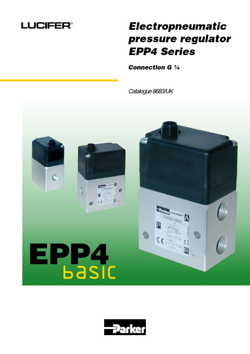
Catalogue 8683/UKElectropneumatic pressure regulator EPP4 SeriesConnection G ¼TheECONOMIC solution which meets the market requirementsCompact design and lightweight for ease of installationand low inertia on moving robots. High responsiveness and low Hysteresis (0.5%)for accurate and fast adjustment of the controlled pressure.Low power consumption (2.2W), energy savingscompatible with environment protection.The productAn electropneumatic pressure regulators G 1/4 which, by means of an integrated electronic control system and pulse width modulated solenoid valves, controls the output pressure proportionally to an analogue electrical signal. A high precision is achieved by means of an internal feedback through an integrated pressure sensor.ApplicationsPressure control independent of flow in electropneumatic control systems, in particular in the following industries: - Robotics: welding, painting lines - Paper and printing: tension regulations, speed-and brake control for rolls - Machine tools: plastic moulding, laser welding, presses, polishing - Trucks and Trains: control of adaptive suspensions.Benefits-Simplification of control systems by reducing the number of components andpermitting more flexibility of the controls with non negligible increase of the productivity (performances, quality, reliability) - Very fast response times- Excellent linearity and hysteresis - No air consumption in rest position-Direct interface to programmable controllers.Catalogue 8683/UKEPP4 Pressure RegulatorParker Lucifer SAFluid Control Division Europe 1227 Carouge/Geneva Switzerland2Printing machineWelding robotTECHNICAL DATAFluid: Lubricated or non lubricated air and neutral gases.Recommended filtration: 50 μm Temperature range: Ambient: 0 to +50 °C.Fluid: 0 to +50 °C.Inlet pressure range: 1 to 12 bar (the inlet pressure must always be at least 1 bar above theregulated pressure) Outlet pressure range: 0.05 to 10 barHysteresis:50 mbar (factory set up).Air consumption at constantcontrol signal: 0 Supply voltage: 24 V DC ± 15 % (Max. ripple 1 V)Power consumption: Max. 2.2 W with 24 V DC and constant changes of the control signal < 0.5 W without change of control signal Control signal: Analog 0 - 10 VAnalog 4 - 20 mAIndicative reponse time: With a volume of 330 cm³ at the outlet of the regulator. Filling: 2 to 4 bar - 2 to 8 bar Step response: ∼ 50 ms - ∼ 100 ms Emptying: 4 to 2 bar - 8 to 2 bar Step response: ∼ 70 ms - ∼ 130 ms Safety position:In case of control signal failure or if it is less than 50mV, the regulatedpressure drops automatically to 0 bar (atmospheric pressure). In case of v oltage suply failure, the regulated pressure will be kept constant Electrical connection: M12 – 4 pin ; 4x 0.34mm 2Life expentancy: > 50 Mio changes of control signal steps.Mounting position: Indifferent (recommended position: upright; electronic part on top). Resistance to vibrations: 30 g in all directions. Outlet signal: No outlet signal. Degree of protection: IP 65. Assembly:Silicone freeElectromagnetic compatibility: In accordance with EN 61000-6-1:2001EN 61000-6-2:2001 EN 61000-6-3:2001 EN 61000-6-4:2001 Installation and setting instructions: See our 12 pages “Bulletin 408014” and appendix supplied with the product.Note: Parker Lucifer reserves the right to change specifications without notification.Catalogue 8683/UKEPP4 Pressure RegulatorParker Lucifer SAFluid Control Division Europe 1227 Carouge/Geneva Switzerland3Description of operationThe EPP4 Series is a family of electrically remote-controlled pneumatic pressure regulators with closed loop integrated electronic control. I t allows regulating the outlet pressure proportionally to an electrical control signal. The EPP4 regulator comprises a traditional servo-operated pneumatic pressure regulator, where the pilot chamber is fed y one or the other of two pulse width modulated 2-way solenoid valves.The pressure sensor measures the outlet pressure of the regulator and provides a feedback signal to the controller. Any difference between the control signal and the feedback signal is converted to a digital signal to energise the coil of one or the other 2-way valves to correct the position of the regulator.The control signal can be a voltage (0-10 V) or a current (4-20 mA). The inlet of the "filling valve" is connected directly to the main inlet P of the regulator; when energised this valve will fill the servo-chamber for increasing the pressure at the outlet A of the regulator.When the other "exhaust valve" is energised (reduction of pressure at the outlet A of the regulator), the pressure of the servo-chamber will be exhausted through a discharge orifice located between the cover and the body and directly fed to the atmosphere without silencer.An option exists to collect the exhaust via the quick exhaust R (Upon request). The exhaust of the main regulated pressure will be made through the quick exhaust R. The use of a conventional silencer is recommended.Both solenoid valves assure the filling or emptying of the servo-chamber in order to increase or decrease the pressure at the outlet of the regulator. n rest position of the valves all ports are blocked.Catalogue 8683/UKEPP4 Pressure RegulatorParker Lucifer SAFluid Control Division Europe 1227 Carouge/Geneva Switzerland4Stand by positionFilling position Emptying positionBlock diagramThe controller receives both the control signal (set pressure) and the feedback signal from the sensor (outlet pressure).Any difference between the two amplifier inputs results in a corresponding output which drives the appropriate 2-way pulse width modulated solenoid valve so that the pilot piston moves to correct the pressure.Hysteresis CurveFlow CurveOutlet pressure in function of flow at constant control signal (P1 = 10 bar)Catalogue 8683/UK EPP4 Pressure RegulatorParker Lucifer SAFluid Control Division Europe 1227 Carouge/Geneva Switzerland5DimensionsThe male connector adopted on the EPP4 is a standard 4 pole-M12, without the pin number 4:The female connector to mount is the 4 pole M12 connector (IEC 61076-2-101 model LF) where the pin number 4 is not connected.AccessoriesMounting bracket (automatically supplied with each EPP4)2x M4 x 10Catalogue 8683/UK EPP4 Pressure RegulatorParker Lucifer SAFluid Control Division Europe 1227 Carouge/Geneva Switzerland6How to order:Reference Control signalOutlet pressureP4BG2001A002 0 – 10 V 0 – 10 bar P4BG2001A003 4 – 20 mA 0 – 10 bar P4BG2001A004 0 – 10 V 0 – 6 bar P4BG2001A005 4 – 20 mA 0 – 6 bar P4BG2001A006 0 – 10 V 0 – 5 bar P4BG2001A007 4 – 20 mA 0 – 5 bar P4BG2001A008 0 – 10 V 0 – 7 bar P4BG2001A009 4 – 20 mA0 – 7 barAsk your agent for any specific calibration. Ask your agent for the NPT version. Cable + connector not included.Catalogue 8683/UKEPP4 Pressure RegulatorParker Lucifer SAFluid Control Division Europe 1227 Carouge/Geneva Switzerland7Parker Lucifer SAFluid Control Division Europe16, ch. du Faubourg de Cruseilles1227 Carouge/Geneva – SwitzerlandTel. +41 22 307 71 11 – Fax +41 22 307 71 10 /fcde 8683/UK June 08。


油研YUKENPV2R系列叶片泵PV2R Series Vane PumbPV2R系列叶片泵是专为低噪声工作而开发的高压高性能叶片泵…其主要特点:1、内部采用圆弧叶片,以提高定子和叶片的寿命;定子采用高次方无冲击过渡曲线,使压力和流量脉动最小,噪声更低。
本公司这一系列的叶片泵产品,具有结构合理,脉动小,噪声低,可靠性高的特点。
2、可以替代国外进口和引进的同类产品,广泛用于机床,塑机,压铸机,冶金机械,工程机械等产品上。
型号有PV2R系列叶片泵:PV2R1-6-F-RAA-4222 PV2R1-10-F-RAA-4222PV2R1-12-F-RAA-41 PV2R1-14-F-RAA-41PV2R1-17-F-RAA-41 PV2R1-19-F-RAA-41PV2R1-23-F-RAA-41 PV2R1-25-F-RAA-41PV2R1-28-F-RAA-41 PV2R1-31-F-RAA-41PV2R2-26-F-RAA-41 PV2R2-33-F-RAA-41PV2R2-41-F-RAA-41 PV2R2-47-F-RAA-41PV2R2-53-F-RAA-41 PV2R2-59-F-RAA-41PV2R2-65-F-RAA-41 PV2R3-52-F-RAA-31PV2R3-60-F-RAA-31 PV2R3-66-F-RAA-31PV2R3-76-F-RAA-31 PV2R3-94-F-RAA-31PV2R3-116-F-RAA-31 PV2R4-136-F-RAA-30PV2R4-153-F-RAA-30 PV2R4-184-F-RAA-30PV2R4-200-F-RAA-30 PV2R4-237-F-RAA-30PV2R双联泵PV2R12。
PV2R13。
PV2R14。
PV2R23。
PV2R24。
PV2R34。
AR系列柱塞泵AR16、AR22;AR16-FR01C-20 AR22-FR01C-20 AR16-FR01B-20 AR22-FR01B-20A系列变量柱塞泵A10、A16、A22、A37、A56、A70、A90、A145YUKEN:A系列变量柱塞泵A10-F-R-01-C-K-10YUKEN:A系列变量柱塞泵A10-F-R-01-B-K-10YUKEN:A系列变量柱塞泵A10-F-R-01-H-K-10YUKEN:A系列变量柱塞泵A10-L-R-01-C-K-10YUKEN:A系列变量柱塞泵A10-L-R-01-B-K-10YUKEN:A系列变量柱塞泵A10-L-R-01-H-K-10YUKEN:A系列变量柱塞泵A16-F-R-01-C-K-32YUKEN:A系列变量柱塞泵A16-F-R-01-B-K-32YUKEN:A系列变量柱塞泵A16-F-R-01-H-K-32YUKEN:A系列变量柱塞泵A16-L-R-01-C-K-32YUKEN:A系列变量柱塞泵A16-L-R-01-B-K-32YUKEN:A系列变量柱塞泵A16-L-R-01-H-K-32YUKEN:A系列变量柱塞泵A16-F-R-01-C-S-K-32YUKEN:A系列变量柱塞泵A16-F-R-01-B-S-K-32YUKEN:A系列变量柱塞泵A16-F-R-01-H-S-K-32YUKEN:A系列变量柱塞泵A16-L-R-01-C-S-K-32YUKEN:A系列变量柱塞泵A16-L-R-01-B-S-K-32YUKEN:A系列变量柱塞泵A16-L-R-01-H-S-K-32YUKEN:A系列变量柱塞泵A22-F-R-01-C-K-32YUKEN:A系列变量柱塞泵A22-F-R-01-H-K-32 YUKEN:A系列变量柱塞泵A22-L-R-01-C-K-32 YUKEN:A系列变量柱塞泵A22-L-R-01-B-K-32 YUKEN:A系列变量柱塞泵A22-F-R-01-C-S-K-32 YUKEN:A系列变量柱塞泵A22-F-R-01-B-S-K-32 YUKEN:A系列变量柱塞泵A22-L-R-01-C-S-K-32 YUKEN:A系列变量柱塞泵A22-L-R-01-B-S-K-32 YUKEN:A系列变量柱塞泵A37-F-R-04-H-K-A-32366 YUKEN:A系列变量柱塞泵A37-F-R-01-B-K-32 YUKEN:A系列变量柱塞泵A37-F-R-01-H-K-32 YUKEN:A系列变量柱塞泵A37-L-R-01-C-K-32 YUKEN:A系列变量柱塞泵A37-L-R-01-B-K-32 YUKEN:A系列变量柱塞泵A37-L-R-01-H-K-32 YUKEN:A系列变量柱塞泵A37-F-R-01-C-S-K-32 YUKEN:A系列变量柱塞泵A37-F-R-01-B-S-K-32 YUKEN:A系列变量柱塞泵A37-F-R-01-H-S-K-32 YUKEN:A系列变量柱塞泵A37-L-R-01-C-S-K-32 YUKEN:A系列变量柱塞泵A37-L-R-01-B-S-K-32 YUKEN:A系列变量柱塞泵A37-L-R-01-H-S-K-32 YUKEN:A系列变量柱塞泵A37-F-R-01-C-K-32 YUKEN:A系列变量柱塞泵A37-F-R-01-B-K-32 YUKEN:A系列变量柱塞泵A37-F-R-01-H-K-32 YUKEN:A系列变量柱塞泵A37-L-R-01-C-K-32 YUKEN:A系列变量柱塞泵A37-L-R-01-B-K-32YUKEN:A系列变量柱塞泵A37-F-R-01-C-S-K-32 YUKEN:A系列变量柱塞泵A37-F-R-01-B-S-K-32 YUKEN:A系列变量柱塞泵A37-F-R-01-H-S-K-32 YUKEN:A系列变量柱塞泵A37-L-R-01-C-S-K-32 YUKEN:A系列变量柱塞泵A37-L-R-01-B-S-K-32 YUKEN:A系列变量柱塞泵A37-L-R-01-H-S-K-32 YUKEN:A系列变量柱塞泵A56-F-R-01-C-K-32 YUKEN:A系列变量柱塞泵A56-F-R-01-B-K-32 YUKEN:A系列变量柱塞泵A56-F-R-01-H-K-32 YUKEN:A系列变量柱塞泵A56-L-R-01-C-K-32 YUKEN:A系列变量柱塞泵A56-L-R-01-B-K-32 YUKEN:A系列变量柱塞泵A56-L-R-01-H-K-32 YUKEN:A系列变量柱塞泵A56-F-R-01-C-S-K-32 YUKEN:A系列变量柱塞泵A56-F-R-01-B-S-K-32 YUKEN:A系列变量柱塞泵A56-F-R-01-H-S-K-32 YUKEN:A系列变量柱塞泵A56-L-R-01-C-S-K-32 YUKEN:A系列变量柱塞泵A56-L-R-01-B-S-K-32 YUKEN:A系列变量柱塞泵A56-L-R-01-H-S-K-32 YUKEN:A系列变量柱塞泵A70-F-R-01-C-S-60 YUKEN:A系列变量柱塞泵A70-F-R-01-B-S-60 YUKEN:A系列变量柱塞泵A70-F-R-01-H-S-60 YUKEN:A系列变量柱塞泵A70-L-R-01-K-S-60 YUKEN:A系列变量柱塞泵A70-L-R-01-C-S-60 YUKEN:A系列变量柱塞泵A70-L-R-01-B-S-60YUKEN:A系列变量柱塞泵A70-L-R-01-K-S-60 YUKEN:A系列变量柱塞泵A90-F-R-01-C-S-60 YUKEN:A系列变量柱塞泵A90-F-R-01-B-S-60 YUKEN:A系列变量柱塞泵A90-F-R-01-H-S-60 YUKEN:A系列变量柱塞泵A90-L-R-01-K-S-60 YUKEN:A系列变量柱塞泵A90-L-R-01-C-S-60 YUKEN:A系列变量柱塞泵A90-L-R-01-B-S-60 YUKEN:A系列变量柱塞泵A90-L-R-01-H-S-60 YUKEN:A系列变量柱塞泵A90-L-R-01-K-S-60 YUKEN:A系列变量柱塞泵A145-F-R-01-C-S-60 YUKEN:A系列变量柱塞泵A145-F-R-01-B-S-60 YUKEN:A系列变量柱塞泵A145-F-R-01-H-S-60 YUKEN:A系列变量柱塞泵A145-L-R-01-K-S-60 YUKEN:A系列变量柱塞泵A145-L-R-01-C-S-60 YUKEN:A系列变量柱塞泵A145-L-R-01-B-S-60 YUKEN:A系列变量柱塞泵A145-L-R-01-H-S-60 YUKEN:A系列变量柱塞泵A145-L-R-01-K-S-60。
丹尼逊液压技术4DP03/06-T 系 列 CETOP 07/08 规 格 A 型 设 计带阀芯位置反馈控制的电液比例方向控制阀样本号:4-SH 3610-BJan.2002Web: E-mail: sales@Back to Index概 述实现液压系统的无级调速控制,优化系统的工作品质; 在小信号范围内,也能有效地对流量作精确的控制; 具有 50%流道比的大阀芯结构型式,可实现对面积比为 2:1 的差动液压缸的控制; 结构简单,抗污染能力强,工作可靠; 与 DENISON 的配套放大器配合使用,可获得良好的动态特性和高控制精度; 电气连接插座符合 ISO 4400 标准; 螺纹连接型的反馈信号电气连接件符合 EMC 及 DIN / VDE 0660-208 A6 标准; 阀安装连接尺寸符合 ISO 4401 标准; 所有产品出厂前均通过严格的出厂试验; 全球范围的丹尼逊技术服务。
特点简介带位置反馈的电液比例方向控制阀主要用于要求滞环小、重复精度高及动态特性好 的液压控制系统。
输入的指令电信号(设定值)通过比例放大器处理后送入先导阀,控制主级阀输出 相应的液压流量(实际值) 。
先导控制阀主级阀由一上置的开环控制比例方向先导阀控制,该先导阀的安装面符合 ISO 4401 标准。
如果预期系统压力存在较大的波动,建议选用主级与先导级之间装有叠加式先导减 压阀的型式(带 R1 选项) 。
主级阀芯带有节流槽口,并连接有反馈位移传感器(LVDT) ,节流槽口的形状可在 两侧为 5 bar 的规定压差下,建立起与输入信号成正比的确定流量(见第 6 页图表) 。
对于 2:1 差动液压缸,可采用“Q/2”型的阀芯,通过“型号代码”中的“阀芯型式” 代号“A”或“B”可予以选择。
机械磨擦力、液动·力或压力波动引起的设定值与实际值之间的偏差,将通过反馈 位移传感器和优化的专用 DENISON 比例放大器之间的相互作用予以纠正。
先导回路减压阀主级阀比例放大器与本系列阀配套开发的比例放大器的回路框图、接线图以及附件等,将在此样本的 后面部分作详细介绍。
此样本中所列的本型比例阀的技术参数,尤其是动态性能, 均是在采用该专用放大器下得到的。
图形符号双电磁铁 4D03 3T 型电液比例方向阀剖视图Back to Index1技术参数双电磁铁 4D06 3T 型电液比例方向阀剖视图综合及液压参数♦ 结构型式 ♦ 遮盖量 ♦ 有效遮盖量 / 指令信号 ♦ 安装姿态 ♦ 安装方式 ♦ 最高工作压力 - 内泄式 - 外泄式 ♦ 先导控制压力(X 口) ♦ 流量 ♦ 公称流量 - 4DP03 规格 - 4DP06 规格 ♦ 推荐最大流量 - 4DP03 规格 - 4DP06 规格 ♦ 油液温度范围 ♦ 环境温度范围 ♦ 油液粘度范围 ♦ 滞环 ♦ 重复精度 ♦ 响应时间滑阀型,比例控制,带位置反馈 ≈15% 10%(采用 701-00632-8 比例放大器) 任意,但建议水平安装 板式,安装面尺寸符合 ISO 4401 P, A, B 350 bar 350 bar T 210 bar 350 bar Y 210 bar 210 bar最高:350 bar 注:R1 选项先导减压阀出厂设定压力为:50 bar 见“特性曲线” (每控制边压差△P = 5 bar 时) 100 / 130 / 200 l/min 200 / 250 / 400 l/min (倍流量工况下) 500 l/min 700 l/min -18 ~ +80° C -10 ~ +50° C 10 ~ 650 cSt,最佳 30 cSt ≦1% ≦0.5% (先导控制压力 50 bar,每控制边压差△P=5 bar,电 磁铁电压 12V 时: ) 4DP03-T 4DP06-T 见第 5 页图线 见第 6 页图线 见第 5 页图线 见第 6 页图线 石油基抗磨液压油(符合 DENISON HF-0 及 HF-2 规 范) ,如:符合 DIN 51524/25 标准的矿物油。
样本规 定的最高额定参数, 均在以此类油液作为工作介质的 基础上给出的。
良好的油液清洁度能有效地延长元件的使用寿命。
不-阶跃信号 0 ~ 100% -阶跃信号 100% ~ 0 ♦ 工作油液2Back to Index技术参数同的应用工况, 污染物的侵入和产生会有不同, 因此, 应对各种应用工况的污染情况作出具体的分析, 从而 确定相应的过滤方法以满足保持油液清洁度的要求。
电气参数♦ 电源电压 ♦ 线圈电阻 - 冷态 20° C - 热态 50° C ♦ 公称电流 ♦ 最大电流 ♦ 线圈最高工作温度 ♦ 防护等级 ♦ 相对工作周期12 V DC 3.7Ω 4.51Ω 2.2 A 2.5 A +155° C(工作温度级别 F) IP 65(DIN 40050) 100% 24 V DC ±20% <0.04 mA pp ≦40 mA 4 ~ 20 mA 1.6 A/mm ±9% ±5 mm ≦±0.01%行程 /° C位移传感器参数♦ 电源电压 Us ♦ 容许输出流量波动 Iout pp ♦ 耗损电流 Is ♦ 输出信号 Iout ♦ 灵敏度 ♦ 检测行程 ♦ 温度漂移Back to Index3型号代码 型号代码 4DP • • 1 1系列代号03 = Cetop 07 规格比例方向控制阀 06 = Cetop 08 规格比例方向控制阀3 2T 3• • • • • • 03 4 5 6A 7• 8G12 • • 9 10•• 11•• 12•• 132 3 4阀体型式3 = 标准型控制方式T = 电液控制,带阀芯位置反馈阀芯型式5流量 P-A; B-T 或 P-B; A-T4DP03 4DP06 F100 = 100 l/min F200 = 200 l/min F130 = 130 l/min F250 = 250 l/min F200 = 200 l/min F400 = 400 l/min (每控制边压差△P = 5 bar 时) A2, A3, B2 及 B3 型阀芯不适用6 7 8阀芯位置03 = 3 位(a, o, b)弹簧对中在“o”位设计号 密封件等级1 = 丁晴橡胶 NBR, 标准型 5 = 氟橡胶 FPM(Viton®)9 10电磁铁电压G12 = 12 V DC电气连接无代号 = 不带电插头 C1 = PG11(电磁铁)及 PG9(位移传感器)插头11先导回路连接无代号 = 外控外泄 X = 内控外泄 Y = 外控内泄 XY = 内控内泄12液压辅件无代号 = 不带先导回路减压阀 R1= 带先导回路减压阀13修改代号N0 = 不带手动监控操作4Back to Index特 性 曲 线 (4DP03-T)阶跃响应时间 (4DP03-T) 流量 / 指令特性曲线 (4DP03-T) 每控制边压差△p = 5 bar 时 阀芯型式 02 / P-A;P-B先导控制压力 10 bar 时行程 %流量 Q(l/min)指令信号(%)阀芯型式 02 / A-T;B-T时间 ms 先导控制压力 50 bar 时 流量 Q(l/min)指令信号(%) 行程 %阀芯型式 43时间 ms 先导控制压力 100 bar 时流量 Q(l/min)指令信号(%)其它 Q 特性举例虚线所示为相对于放大器因子设定 为 10%指令信号时的特性曲线时间 ms流量 Q(l/min)行程 %指令信号(%)注:所有实线表示的曲线均在放大器的设置 l min = 0 的条件下测得。
公称流量 不同压差下的流量可由下列公式进行计算:Q X=Q N∆p X 5 QN–压差 5 bar 下的公称流量; QX–压差△pX 下的流量。
Back to Index5特 性 曲 线 (4DP06-T)阶跃响应时间 (4DP06-T) 流量 / 指令特性曲线 (4DP06-T) 每控制边压差△p = 5 bar 时 阀芯型式 02 / P-A;P-B先导控制压力 10 bar 时行程 %流量 Q(l/min)指令信号(%)阀芯型式 02 / A-T;B-T时间 ms 流量 Q(l/min)先导控制压力 50 bar 时行程 %指令信号(%)阀芯型式 43时间 ms先导控制压力 100 bar 时流量 Q(l/min)指令信号(%)其它 Q 特性举例虚线所示为相对于放大器因子设定 为 10%指令信号时的特性曲线流量 Q(l/min)行程 %时间 ms指令信号(%)注:所有实线表示的曲线均在放大器的设置 l min = 0 的条件下测得。
公称流量 不同压差下的流量可由下列公式进行计算:Q X=Q N∆p X 5 QN–压差 5 bar 下的公称流量; QX–压差△pX 下的流量。
6Back to Index外 形 尺 寸 (4DP03-T)重量:11.0 kg电气插头 PG11 符合 ISO 4400手动监控操作柱销先导减压阀,选项代号 R1 重量:1.6 kg图形符号(详图) 带先导回路减压阀(R1 选项)先导阀 4D01 3E02F10 03B1 G12图形符号(简图)电气接头 电磁铁接放大器接放大器过渡位置机能接放大器 X-外控口 Y-外泄口1) 供货时,按订货要求的先导回路连接方式安装螺堵。
Back to Index7外 形 尺 寸 (4DP06-T)重量:18.6 kg电气插头 PG11 符合 ISO 4400手动监控操作柱销 先导减压阀,选项代号 R1 重量:1.6 kg图形符号(详图) 带先导回路减压阀(R1 选项)先导阀 4D01 3E02F10 03B1 G12图形符号(简图)电气接头 电磁铁接放大器接放大器过渡位置机能接放大器 X-外控口 Y-外泄口1) 供货时,按订货要求的先导回路连接方式安装螺堵。
8Back to Index安装面尺寸 安装面尺寸,符合 ISO 4401 标准4DP03 系列比例方向阀安装面(SETOP 07 规格)安装面加工要求 平面度 0.01 / 100 mm 粗糙度油口功能 P A, B T X Y = = = = = 压力油口 工作油口 回油口 外控或外泄油口 外泄或外控油口密封圈(丁腈橡胶 NBR) A, B, T 21.89 x 2.62 691-00118-0 P X, Y 23.47 x 2.62 691-00119-0 10.82 x 1.78 691-00013-04DP06 系列比例方向阀安装面(SETOP 08 规格)安装面加工要求 平面度 0.01 / 100 mm 粗糙度油口功能 P A, B T X Y = = = = = 压力油口 工作油口 回油口 外控或外泄油口 外泄或外控油口密封圈(丁腈橡胶 NBR) A, B, T 28.17 x 3.53 691-00216-0 P X, Y 31.34 x 3.53 691-00218-0 20.29 x 2.62 691-00117-0Back to Index9安装底板阀安装面尺寸符合ISO 4401标准4DP03(SETOP 07规格)系列比例方向阀用安装底板 重量:≈ 8.3 kg数量 安装螺钉订货号4 M10 x 65, DIN 912; 10.9级 700-71449-82M6 x 60, DIN 912; 10.9级 700-70806-8注:安装螺钉包括在安装底板的订货中;比例方向阀订货时若不带订安装底板,则需单独订购安装螺钉。