ST LinkIII接口定义
- 格式:doc
- 大小:80.00 KB
- 文档页数:2


主板常用接口介绍及定义刚接触电脑的朋友面对着计算机后背那密密麻麻的各种接口和一大把连接线往往会不知所措;接触电脑久的朋友有的时候想搞一些小点子,但常常会找不到各种接口的针脚定义;如果你有以上的经历,那么这一篇文章想必会给您带来一点帮助,那就是外部接口大集合。
首先是ATX 20-Pin电源接口电源接口,根据下图你可方便判断和分辨。
现在为提高CPU的供电,从P4主板开始,都有个4P接口,单独为CPU供电,在此也已经标出。
鼠标和键盘绝大多数采用PS/2接口,鼠标和键盘的PS/2接口的物理外观完全相同,初学者往往容易插错,以至于业界不得不在PC'99规范中用两种不同的颜色来将其区别开,而事实上它们在工作原理上是完全相同的,从下面的PS/2接口针脚定义我们就可以看出来。
上图的分别为AT键盘(既常说的大口键盘),和PS2键盘(即小口键盘),如今市场上PS2键盘的数量越来越多了,而AT键盘已经要沦为昨日黄花了。
因为键盘的定义相似,所以两者有共同的地方,各针脚定义如下:1、DATA 数据信号2、空3、GND 地端4、+5V5、CLOCK 时钟6 空(仅限PS2键盘)USB(Universal Serial Bus,通用串行总线)接口是由Compaq、IBM、Microsoft 等多家公司于1994年底联合提出的接口标准,其目的是用于取代逐渐不适应外设需求的传统串、并口。
1996年业界正式通过了USB1.0标准,但由于未获当时主流的Win95支持(直到Win95 OSR2才通过外挂模块提供对USB1.0的支持)而未得到普及,直到1998年USB1.1标准确立和Win98内核正式提供对USB接口的直接支持之后,USB才真正开始普及,到今天已经发展到USB2.0标准。
USB接口的连接线有两种形式,通常我们将其与电脑接口连接的一端称为“A”连接头,而将连接外设的接头称为“B”连接头(通常的外设都是内建USB数据线而仅仅包含与电脑相连的“A”连接头)。

PS2、USB、DB-9、网卡、串口、并口、VGA针脚定义及接口定义图以下为仅为主板各接口的针脚定义,外接出来的设备接口则应与主板对应接口针脚定义相反,如鼠标的主板接口定义为6——数据,4——VCC,3——GND,1——时钟,鼠标线的接口定义则与之相反为5——数据,3——VCC,4——GND,2——时钟;其他外接设备与此相同。
首先是ATX20-Pin电源接口电源接口,根据下图你可方便判断和分辨。
现在为提高CPU的供电,从P4主板开始,都有个4P接口,单独为CPU供电,在此也已经标出。
鼠标和键盘绝大多数采用PS/2接口,鼠标和键盘的PS/2接口的物理外观完全相同,初学者往往容易插错,以至于业界不得不在PC'99规范中用两种不同的颜色来将其区别开,而事实上它们在工作原理上是完全相同的,从下面的PS/2接口针脚定义我们就可以看出来。
上图的分别为AT键盘(既常说的大口键盘),和PS2键盘(即小口键盘),如今市场上PS2键盘的数量越来越多了,而AT键盘已经要沦为昨日黄花了。
因为键盘的定义相似,所以两者有共同的地方,各针脚定义如下:1、DATA 数据信号2、空3、GND 地端4、+5V5、CLOCK 时钟6 空(仅限PS2键盘)USB(Universal Serial Bus,通用串行总线)接口是由Compaq、IBM、Microsoft等多家公司于1994年底联合提出的接口标准,其目的是用于取代逐渐不适应外设需求的传统串、并口。
1996年业界正式通过了USB1.0标准,但由于未获当时主流的Win95支持(直到Win95 OSR2才通过外挂模块提供对USB1.0的支持)而未得到普及,直到1998年USB1.1标准确立和Win98内核正式提供对USB接口的直接支持之后,USB才真正开始普及,到今天已经发展到USB2.0标准。
USB接口的连接线有两种形式,通常我们将其与电脑接口连接的一端称为“A”连接头,而将连接外设的接头称为“B”连接头(通常的外设都是内建USB数据线而仅仅包含与电脑相连的“A”连接头)。

西门康、英飞凌三电平驱动方案2AB30A17K‐3L‐I/S是基于青铜剑自主开发的2QD30A17K‐I驱动核的驱动底座,为英飞凌和西门康三电平IGBT而设计。
2AB30A17K‐3L‐I/S可以驱动西门康SKiM601TMLI12E4B 和英飞凌F3L400R12PT4_B26三电平IGBT模块。
外置两组驱动接口使得它可以支持2单元SKiM601TMLI12E4B和F3L400R12PT4_B26的并联。
图 1 2AB30A17K‐3L实物图目 录驱动方案概述 (3)基本电气特性 (驱动核2QD30A17K‐I) (4)底座板和门极板尺寸图 (5)底座板和门极板引脚接口定义 (8)2AB30A17K‐3L 原边牛角引脚定义 (8)2AB30A17K‐3L次边接口定义 (8)MA20A12K‐3L‐S接口定义 (9)MA20A12K‐3L‐I接口定义 (9)底座板门极板电路原理图 (10)2AB30A17K‐3L 电路原理图 (10)MA20A12K‐3L‐S电路原理图 (13)MA20A12K‐3L‐I电路原理图 (15)2AB30A17K‐3L‐I/S牛角接口电路描述 (17)概述 (17)VCC端口 (17)VDC端口 (17)MOD端口(模式选择端) (17)直接模式 (17)半桥模式 (18)INA、INB(PWM信号输入) (18)SO1、SO2(故障输出) (18)底座板与门极板连接描述 (19)概述 (19)2AB30A17K‐3L与MA20A12K‐3L‐S连接示意图 (19)2AB30A17K‐3L与MA20A12K‐3L‐I连接示意图 (19)联系我们 (20)驱动方案概述2AB30A17K‐3L‐I/S采用了青铜剑公司自主开发的驱动核(2QD30A17K‐I)+适配底座(2AB30A17K‐3L)+SKiM601TMLI12E4B或F3L400R12PT4_B26 IGBT门极适配板(MA20A12K‐3L‐S或MA20A12K‐3L‐I)设计而成,是一款使用方便、成本低的IGBT驱动方案。

1 Smart Link配置 .................................................................................................................................... 1-11.1 Smart Link简介................................................................................................................................. 1-11.1.1 Smart Link概念介绍............................................................................................................... 1-11.1.2 Smart Link运行机制............................................................................................................... 1-21.2 配置Smart Link设备........................................................................................................................ 1-31.2.1 配置准备 ................................................................................................................................ 1-31.2.2 配置Smart Link设备 ............................................................................................................. 1-31.2.3 Smart Link设备配置举例........................................................................................................ 1-41.3 配置相关设备.................................................................................................................................... 1-51.3.1 配置相关设备 ......................................................................................................................... 1-51.3.2 相关设备配置举例.................................................................................................................. 1-51.4 Smart Link显示和维护...................................................................................................................... 1-61.5 Smart Link典型配置举例 .................................................................................................................. 1-61.5.1 单Smart Link组配置举例...................................................................................................... 1-61.5.2 多Smart Link组负载分担配置举例........................................................................................ 1-81 Smart Link 配置1.1 Smart Link 简介如图1-1所示,双上行组网是目前常用组网之一。

三层交换机原理解析1.硬件结构:三层交换机通常由交换芯片、路由芯片和控制芯片组成。
交换芯片负责局部网络内的数据包转发,路由芯片负责不同网络之间的路由选择和转发,控制芯片实现管理和控制功能。
2.数据包的转发:当三层交换机收到一个数据包时,会首先进行数据包解析,提取出源地址和目的地址等信息。
然后,交换芯片会根据目的地址查询自己的转发表,并将数据包转发给相应的端口。
如果目的地址不在转发表中,交换芯片会将数据包转发给路由芯片进行进一步转发。
3.转发表的更新:为了实现数据包的快速转发,交换芯片会维护一个转发表。
该转发表记录了不同设备的MAC地址和相应的端口信息。
通常,转发表会通过链路层的协议(如ARP)来获得和更新设备的MAC地址。
当网络中的设备进行通信时,交换芯片会根据转发表来决定转发路径。
4.路由选择:当数据包需要跨越不同网络时,交换芯片会将数据包转发给路由芯片进行路由选择。
路由芯片通过学习网络拓扑和掌握网络的路由信息,来选择最佳的路由路径,并且将数据包转发到合适的出口端口。
5.VLAN划分:三层交换机支持虚拟局域网(VLAN)的划分。
VLAN的划分可以将一个物理网络划分成多个逻辑上的子网,不同的子网可以根据需要进行独立的管理和配置。
VLAN的划分可以提高网络的安全性和性能。
6.数据包过滤:三层交换机可以通过过滤规则对数据包进行过滤。
过滤规则可以根据源地址、目的地址、协议类型等条件进行设置,从而实现对网络中的数据包进行控制和管理。
7.流量控制:三层交换机支持流量控制功能,可以根据网络的负载情况和带宽情况来控制端口的传输速率。
通过流量控制,可以防止网络拥塞和丢包现象的发生,从而提高网络的性能和稳定性。
总结起来,三层交换机通过硬件实现了路由和交换功能,并且支持VLAN划分、数据包过滤和流量控制等功能。
它可以在局部网络中快速转发数据包,并且能够跨越不同网络进行路由选择和转发,从而提高了网络的性能和可靠性。
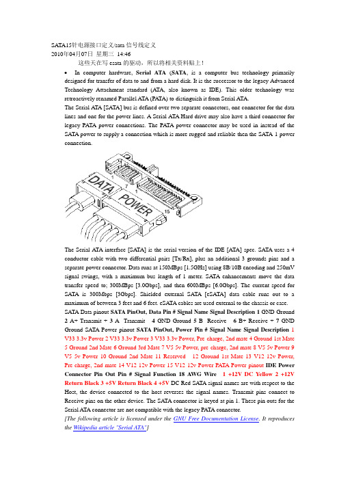
SATA15针电源接口定义/sata信号线定义2010年04月07日星期三14:46这些天在写esata的驱动,所以将相关资料贴上!•In computer hardware, Serial ATA(SATA, is a computer bus technology primarily designed for transfer of data to and from a hard disk. It is the successor to the legacy Advanced Technology Attachment standard (ATA, also known as IDE). This older technology was retroactively renamed Parallel ATA (PA TA) to distinguish it from Serial ATA.The Serial ATA [SATA] bus is defined over two separate connectors, one connector for the data lines and one for the power lines. A Serial ATA Hard drive may also have a third connector for legacy PATA power connections. The PATA power connector may be used in instead of the SATA power to supply a connection which is more rugged and reliable then the SATA-1 power connection.The Serial ATA interface [SATA] is the serial version of the IDE [ATA] spec. SATA uses a 4 conductor cable with two differential pairs [Tx/Rx], plus an additional 3 grounds pins and a separate power connector. Data runs at 150MBps [1.5GHz] using 8B/10B encoding and 250mV signal swings, with a maximum bus length of 1 meter. SATA enhancements move the data transfer speed to; 300MBps [3.0Gbps], and then 600MBps [6.0Gbps]. The current speed for SATA is 300Mbps [3Gbps]. Shielded external SATA [eSATA] data cable runs out to a maximum of between 3 feet and 6 feet. eSATA cables are used external to the chassis or case.SATA Data pinout SATA PinOut, Data Pin #Signal Name Signal Description1 GND Ground 2A+ Transmit + 3A- Transmit - 4GND Ground 5B- Receive - 6B+ Receive + 7GND Ground SATA Power pinout SATA PinOut, Power Pin #Signal Name Signal Description1 V33 3.3v Power 2 V33 3.3v Power 3 V33 3.3v Power, Pre-charge, 2nd mate 4 Ground 1st Mate5 Ground 2nd Mate6 Ground 3rd Mate7 V5 5v Power, pre-charge, 2nd mate8 V5 5v Power 9V5 5v Power 10 Ground 2nd Mate 11 Reserved - 12 Ground 1st Mate 13 V12 12v Power, Pre-charge, 2nd mate 14 V12 12v Power 15 V12 12v Power PATA Power pinout IDE Power Connector Pin Out Pin #Signal Function18 A WG Wire 1 +12V DC Yellow 2 +12V Return Black 3 +5V Return Black 4 +5V DC Red SATA signal names are with respect to the Host, the device connected to the host reverses the signal names. Transmit pins connect to Receive pins on the other device. The SATA connector is keyed at pin 1. These pin outs for the Serial ATA connector are not compatible with the legacy PATA connector.[The following article is licensed under the GNU Free Documentation License. It reproduces the Wikipedia article "Serial ATA"]SATA 1.5 Gb/sFirst-generation Serial ATA interfaces, also known as SATA/150, run at 1.5 Gigahertz (GHz). Serial A TA uses 8B/10B encoding at the physical layer. This encoding scheme has an efficiency of 80%, resulting in an actual data transfer rate of 1.2 Gigabits per second (Gb/s), or 150 megabytes per second (MB/s). The relative simplicity of a serial link and the use of LVDS allow both the use of longer drive cables and an easier transition path to higher speeds.SATA 3.0 Gb/sSoon after SATA's introduction, enhancements were made to the standard. A 3Gb/s signalling rate was added to the PHY layer, offering up to twice the data throughput. To ensure seamless backward compatibility between older SATA and the newer faster SATA/3Gbs devices, the latter devices are required to support the original 1.5Gb/s rate. In practice, some older SATA systems that do not support SATA speed negotiation require the peripheral drive's speed be manually hardlimited to 150Â MB/s with the use of a jumper for a 300Â MB/s drive.Like SATA 1.5Gb/s, SATA 3Gb/s uses 8B/10B encoding resulting in an actual data transfer rate of 2.4 Gb/s, or 300 MB/s.The 3.0Â Gb/s specification has been very widely referred to as “Serial ATA II” (“SATA II”), contrary to the wishes of the Serial ATA standards organization that authored it. The official website notes that SATA II was in fact that organization's name at the time, the SATA 3Gb/s specification being only one of many that the former SATA II defined, and suggests that “SA TA 3Gb/s” be used instead. (The Serial A TA standards organization has since changed names, and is now “The Serial ATA International Organization”, abbreviated SA TA-IO.) SATA-IO plans to further increase the maximum throughput of Serial ATA to 600Â MB/s around the year 2007.SATA 3Gb/s is sometimes also referred to as SATA/300 or SATA II, continuing the line of PATA/100, PATA/133 and SATA/150.SATA 6.0 Gb/sSATA-IO plans to make a 6.0 Gb/s standard. Although the theoretical thoroughput would be doubled, conventional hard disks can't approach saturating this speed. Serial ATA innovationsSATA drops the master/slave shared bus of PATA, giving each device a dedicated cable and dedicated bandwidth. While this requires twice the number of host controllers to support the same number of SATA devices, at the time of SATA's introduction this was no longer a significant drawback. Another controller could be added into a controller ASIC at little cost beyond the addition of the extra seven signal lines and printed circuit board (PCB) space for the cable header.Features allowed for by SATA but not by PA TA include hot-swapping and native command queueing.To ease their transition to SATA, many manufacturers have produced drives which use controllers largely identical to those on their PATA drives and include a bridge chip on the logic board. Bridged drives have a SATA connector, may include either or both kinds of power connectors, and generally perform identically to native drives. They may, however, lack support for some SATA-specific features. As of 2004, all major hard drive manufacturers produce either bridged or native SA TA drives.SATA drives may be plugged into Serial Attached SCSI (SAS) controllers and communicate on the same physical cable as native SAS disks. SAS disks, however, may not be plugged into aSATA controller.Cables and ConnectorsPhysically, the SATA power and data cables are the most noticeable change from Parallel A TA. The SATA standard defines a data cable using seven conductors and 8Â mm wide wafer connectors on each end. SATA cables can be up to 1 m (39 in) long.PATA ribbon cables, in comparison, carry either 40- or 80-conductor wires and are limited to 46 cm (18 in) in length. The reduction in conductors makes SATA connectors and cables much narrower than those of PATA, thus making them more convenient to route within tight spaces and reducing obstructions to air cooling. Unlike early PATA connectors, SATA connectors are keyed — it is not possible to install cable connectors upside down without considerable force.The SATA standard also specifies a power connector sharply differing from the four-pin Molex connector used by PATA drives and many other computer components. Like the data cable, it is wafer-based, but its wider 15-pin shape should prevent confusion between the two. The seemingly large number of pins are used to supply three different voltages if necessary —3.3Â V, 5Â V, and 12Â V. Each voltage is supplied by three pins gangedtogether (and 5 pins for ground). This is because the small pins cannot supply sufficient current for some devices, so they are combined. One pin from each of the three voltages is also used for hotplugging. The same physical connections are used on 3.5-in (90mm) and 2.5-in (70mm) (notebook) hard disks. Some SATA drives include in PA TA style four-pin Molex connector for use with power supplies that lack the SATA power connector. Also, adaptors are available to convert a PATA style power connector to SATA power connector.External SATAeSATA was standardized in mid-2004, with specifically defined cables, connectors, and signal requirements for external SATA drives. eSATA is characterized by:Full SATA speed for external disks (115MB/s have been measured with external RAID enclosures)•No protocol conversion from IDE/SATA to USB/Firewire, all disk features are available to the host•Cable length is restricted to 2m, USB and Firewire span longer distances.•Minimum and maximum transmit voltage decreased to 400mV - 500mV•Minimum and maximum receive voltage decreased to 240mV - 500mVUSB and Firewire require conversion of all communication with the external disk, so external USB/Firewire enclosures include an IDE or SATA bridge chip that translates from the ATA protocol to USB or Firewire. Drive features like S.M.A.R.T. cannot be exploited that way and the achiveable transfer speed with USB/Firewire is only about half of the entire bus data rate of about 50MB/s. This limited effective data transfer rate becomes very visible when using an external RAID array and also with fast single disks which may yield well over 70MB/s during real use.Currently, most PC motherboards do not have an eSA TA connector. eSATA may be enabled through the addition of an eSATA host bus adapter (HBA) or bracket connector for desktop systems or with a Cardbus or ExpressCard for notebooks.Note:Prior to the final specification for eSATA, there were a number of products designed for external connections of SATA drives. Some of these use the internal SATA connector or even connectors designed for other interface specifications, such as IEEE 1394. These products are not eSA TA compliant.eSATA does not provide power, which means that external 2.5" disks which would otherwise be powered over the USB or Firewire cable need a separate power cable when connected over eSATA.eSATA compared to other buseseSA TA PATA Fire Wire 1394b USB 2.0 Actual Speed 2.4 >Gib/s 1064 Mib/s 786 Mib/s ~375 Mib/sMax. cable length 2 meters 46 centimetres4.5 meters 16 cables canbedaisy chained up to 72meters5 metersPower cablerequired?Yes Yes No NoDevices per Channel 1 (5 withmultiplier)3 (3rd deviceread only)63 127Backward compatibilityThe backward compatibility of SATA hard discs is virtually non-existent in the sense that SATA drives will not work with the same connectors that IDE, SCSI, or any other format of hard drive connect to. It is, however, possible to purchase convertors that attach to the rear of the SATA hard disc and will allow it to function as an IDE drive. This can prove useful in situations where one wishes to use their SATA drive on older motherboards that may not have SATA connections, etc.SATA vs SCSISCSI currently offers transfer rates higher than SATA, but is a more complex bus usually resulting in higher costs to the user. Some drive manufacturers offer longer warranties for SCSI devices, however, indicating a possibly higher manufacturing quality control of SCSI devices compared to PATA/SA TA devices.conn_sata.gif(10.79 KB)3030299030-SATA-15P-RA-core-power-connector-dwg.gif(14.14 KB)类别:电脑技术| | 添加到搜藏| 分享到i贴吧| 浏览(1386) | 评论(0)。

ST推出了STLINK-V3下一代STM8和STM32微控制器代码烧写及调试
探针
意法半导体推出了STLINK-V3下一代STM8 和STM32微控制器代码烧写及调试探针,进一步改进代码烧写及调试灵活性,提高效率。
STLINK-V3支持大容量存储,具有虚拟COM端口和多路桥接功能,烧写性能是上一代探针的三倍,产品价格具市场竞争力,节省应用开发时间,简化设备现场重新编程流程。
除提供典型的JTAG /串行线调试(SWD)和单线接口模块(SWIM)连接外,STLINK-V3的虚拟COM端口(VCP)和多路桥接器还可以通过UART、I2C、SPI或CAN接口或GPIO 引脚与微控制器通信,方便开发人员使用自定义控制命令自动执行测试,并在PC主机上观察运行时数据,或者使用STLINK-V3配合引导加载程序向设备烧写代码,简化产品维护任务。
现有主要开发工具已支持STLINK-V3,允许用户利用STM32Cube编程器等方便的图形环境和Keil®MDK-ARM、IAR™EWARM和基于GCC的IDE等集成开发环境(IDE)的强大功能。
意法半导体还允许免费访问STLINK-V3底层API,以便与自定义或自动化测试平台集成。
作为一套完整的工具,STLINK-V3SET套件包含探针、调试连接器、电缆和支持SWIM 特定功能的适配板,并可以取用多路桥接信号。
用户可以增加一块附加电路板,例如,电压转换器模块,以较低的成本进一步扩展探针的功能。
STLINK-V3SET现在可从st或通过分销商购买。

ST - III Series POWER SUPPLIESUSER MANUALIntroductionThese instructions detail the installation and operation requirements for the ST20-III & ST35-III power supplies. These have been designed for operation in RV’s providing a DC power system, with optional battery back up.The units operate from 240Vac and provide an isolated 13.65Vdc output at 20A and 35A respectively for powering the load and charging of batteries. All the necessary protection and operating features for the load and batteries are provided. An optional DC input is also provided to enable charging of batteries and powering of the load from an external +13.8V DC power source. The units are fully enclosed ready for direct wall mounting. All connections are at the rear of unit providing convenient wiring and installation. User access to all load and battery fusing has been provided from the front of the unit.OperationSafety: Refer to the installation section before operating. Correct installation is the most critical factor in ensuring the safe use of the power supply. If every consideration of these instructions has been satisfied the power supply will be safe to operate.If the AC supply cord is damaged it must be replaced by the manufacturer, its service agent or similarly qualified persons in order to avoid hazard.The unit is rated to charge a single 12V (up to 6 cells) lead acid battery at 100Ahr Capacity. Functional Diagram:AC/DC Power Supply: This provides an isolated 13.65Vdc output for powering of the load and float charging of the battery. Battery current is sensed and monitored by the power supply to ensure that the maximum charging current is not exceeded.Battery Features: The power supply provides full battery management as per the following.The power supply is a four stage battery charger with Boost (VBoost = 14.05V), Float (VFloat = 13.65V), Store (VStore = 13.25V) and Trickle charge modes to ensure long battery life.Battery Charging current is limited to a maximum of 10A (ST20-II) and 15A (ST35-II). This provides optimum life for the batteries.To charge at the maximum battery charge current above, ensure the load current plus battery current is equal or less than the maximum output current. The charging current will be reduced in situations where the difference between the rated output current and the load current (the available charging current), is less than the maximum charging current.Also note that the battery current sense is provided in the “Batt +ve” battery output. For this feature to work, the load “+ve” and battery “Batt +ve” should not be cross connected. (Appliances should not be connected to both the “Batt +ve” and “+ve” terminals of the power supply. Appliances should be connected to the “+ve” and “-ve” load terminals).Low Voltage Disconnection of the batteries is provided to prevent deep discharge of the battery. Automatic reconnection occurs when battery voltage recovers.Battery Current Drain is less than 2mA.Trickle Charge to the battery is always present. When the battery voltage is below the LVD (Low voltage disconnect) re-connect voltage (<10V and the mains power or auxiliary power is available, the battery will be charging at 0.8A. When the battery voltage is sufficient (>10.5V for first power up, 11.5V and 11.7V for subsequent reconnection with and without mains respectively) the LVD will connect the battery and allow float charging at 10A/15A (ST20-II/ST35-II). The Trickle Charge feature is provided to allow “very” flat batteries to be charged at a rate, which will extend their life.Remote Battery Isolate Switch: The ST-III series power supplies allow for connection to a remotely positioned switch that provides a manual disconnection of the battery from the loads and the main charger. When the switch contacts are closed, the battery will be isolated from the loads. NOTE: When the battery is isolated from the loads using the battery isolate switch it will NOT charge at the 10/15 A rate even if the mains is connected to the power supply. In this condition it will ONLY charge at the Trickle charge rate.Front Panel Indicators: The ST-III series power supplies have 3 indicators visible on the front fascia.Mains(GREEN) – is illuminated when mains power is present.Battery(ORANGE) – is illuminated when the battery is connected to the loads.Fault(RED) – is illuminated when there is a fault with the power supply.Battery fuse Blown1Battery connected reverse polarity2Shut down condition (UV and OT)3Main PCB micro controller malfunction4Notes1.Flashing 1s ON, 1s OFF.2.Solid ON.3.Flashing 1s ON, 1s OFF, with no battery connected the power supply may be in hiccupmode which will cause the indication to flash with random duty cycle and frequency.4.Fault Led= Solid On, All other leds = OFF, irrespective of actual mains or LVD status. Auxiliary Power Input: The power supply terminal “Aux In +VE” provides an alternative option for powering of the load and float charging of the batteries when mains voltages are not present. This input is to be powered by a suitable +12V system. (i.e. CAR). The voltage of the auxiliary power source should not exceed 14.8 volts.When operating via the external input, current and voltage control for the battery must be provided from the external source. The ST20-II/35-II does not provide battery current limit or voltage control when operating in this configuration. Trickle Charge is still functional when powered through “Aux In +VE” terminal of power supply.Suitable fuse protection must be provided for this input. A fuse rating not exceeding 20 Amps for ST20-II and 30 Amps for ST35-II must be used.Solar power should be connected directly across the battery terminals with a voltage regulator in series. A solar panel voltage regulator with maximum output voltage not exceeding 14.8 volts must be used at all times. Failure to use a voltage regulator may result in power supply damage. Generator 12 volt outputs should not be connected across battery terminal whilst battery is connected to power supply or connected to the “Aux In +VE” terminal of power supply. Serious power supply damage or internal explosion may occur. If a flat 12 volt battery has to be charged using the generators 12 volt output, it should first be disconnected from the power supply. Once battery has being charged it can then be reconnected to power supply.Power supply unit should only be powered from either 240VAC mains or Auxiliary Power (Auxiliary Power also includes solar power) but not both. Failure to do so may result in damage to power supply.Protection: the power supply provides automatic protection for overload including short circuit, over-voltage, over-temperature and reverse connected battery. In such instances the Fault indicator will illuminate and the power supply will shut down. It will attempt to automatically restart every 5 seconds until such case that the fault is removed.Fusing: Each load circuit and the battery have been fused to provide fault protection and discrimination. Refer to servicing section for maximum fuse ratings.InstallationHost Equipment: The host equipment must ensure that access to the unit (other than the front panel) by the user is prevented.Personnel: Installation is to be carried out only by suitably qualified personnel.Ventilation: Provide a minimum of 80mm clearance above, below and behind the unit. The final enclosure must also provide adequate ventilation to the outside world (or larger internal cavity) to prevent the build up of hot air. Failure to provide adequate ventilation will mean the unit may prematurely trip thermal shut-down. A minimum ventilation of 20,000mm2 to the outside world must be provided.Mechanical and Mounting:After mounting unit, clip on the front fascia (ensure that all locking clips have engaged) and secure with screw located inside the fuse panel door.Orientation: The unit is to be installed with the front fascia in a vertical plane. Failure to do this will cause premature temperature shut-down.Wiring UpMains: This is pre cabled and fitted with AS/NZ mains plug ready for connection to internal GPO. Ensure that the connection to the mains supply is in accordance with the national wiring rules, and that the earth connection is installed.Load, Battery and External DC Input Connections: Connectors are 0.8 x 6.3mm QC tabs. Use mating QC connector suitable for cable size. Connector pin-out is shown below.Cabling sizes: DC cables must be sized to carry the maximum full load current and not exceed the system volt drop requirements. The following cable sizes are recommended.Where cables pass through any part of a metal panel or cover, ensure that a cable gland or bush is fitted to the hole.Battery Connection Procedures:Battery should be connected as per the following steps.Turn power supply off and all 12 volt equipment connected to power supply.Connect positive battery terminal to “Batt +VE” power supply terminal.Connect negative battery terminal to “Batt -VE” power supply terminal or negative chassis ground.If battery is connected to chassis, ensure a connection exist from chassis to “Batt –VE”terminal of power supply.Battery Disconnection Procedures:Battery should be disconnected as per the following steps.Turn power supply off and all 12 volt equipment connected to power supply.Disconnect negative battery terminal connection to “Batt –VE” power supply terminal or negative chassis ground.1.Disconnect positive battery terminal to “Batt +VE” power supply terminal.BatteriesWhen using batteries with this product always consult with the battery manufacturer for a detailed description of the installation, use and maintenance of the battery.Ensure battery has been charged for several days before a major camping trip (Leave the power supply on for at least 2 – 5 days with battery connected).This product is suitable for charging 12V-Sealed Lead-Acid (SLA) batteries including Valve-Regulated Lead-Acid (VRLA) batteries both Absorbed Glass Mat (AGM) and Gel batteries. One or two batteries with max.100Ah capacity each can be charged. Charging current is limited to 10A (ST20-II) and 15A(ST35-II).ServicingPersonnel: This product contains hazardous voltages and energy hazards, which can result in death or injury. Only properly qualified service personnel may service it.There are no internal user serviceable parts. Only the fuses located in the “fuse panel” located on the front panel are serviceable.Isolate mains power, Vext and battery before servicing.Replacement of Fuses: Only the DC output Load and Battery fuses may be replaced.Fuse ratings: Load fuses 20A max, Battery Fuse 35A max.Fuse types: 32V Automotive Bussmann ATC series or Littelfuse 257 series or equivalentSpecificationInput Voltage:ST20-II & ST35-II: 230 – 240Vac nominal, ±10%, 50/60Hz.The power supply will withstand a 5 minute, +15% surge on themaximum nominal voltageInput Surge:< 40A (cold start)Hold-up Time:> 10mS at full load current and over nominal input voltage operatingrangeOutput Current:ST20-II: 20A Continuous (load + battery current)ST35-II: 35A Continuous (load + battery current)Factory Set Voltage 13.65V +/- 0.1V (Vfloat)Load Regulation:< 2%Output RippleVoltage:< 150mVOver VoltageProtection:< 17VOver Current Protection ST20-II: 20A to 25A (load + battery current) ST35-II: 35A to 38A (load + battery current)Battery Current Limit10A ± 1A (ST20-II)15A ± 1A (ST35-II)BatteryConnect/Disconnect Connect: 10.50 ± 0.2V (Input Mains not present) and first power up Connect: 11.70 ± 0.2V (Input Mains not present and not first power up) Connect: 11.50 ± 0.2V (Input Mains present)Disconnect: 10.0 ± 0.2VBattery TrickleCharge0.8A Battery Drain< 2mA. Efficiency:> 84%Cooling Fan Operation ST35-II Only.Cooling fan on temperature of Transformer: 95C + 3 degrees. Cooling fan off temperature of Transformer: 75C + 3 degrees.Ambient0O C – 50O CWeight:< 2kgStandards Safety: AS/NZS 60335-1, AS/NZS 60335-2-29 & AS/NZS 61558EMC CISPR 22 class ACompliance:ERAC+ACMA (RCM)Battery ManagementTo maintain the battery in a good state of health an intelligently controlled charging algorithm is used. The purpose is to ensure that the correct voltages are applied to the battery terminals at the appropriate times throughout it’s usage cycle.To prevent corrosion on the battery positive plate due to continuous float charging current (VFloat = 13.65V), the unit utilises a storage mode voltage (VStore = 13.25V) when no activity on the battery is detected. This extends the battery life. During store mode, the unit exits to boost mode (VBoost = 14.05V) for 15 minutes every 24hrs to maintain charge in the battery. If battery activity is detected during store mode it exits automatically into float mode.For any decision making involving the “loss of mains” detection there is a 2 minute mains debounce period where there must be no mains signal present on the mains detect input for the “no mains” signal to be valid.A detailed description of the operational requirements for the charging algorithm is describedbelow:N/A Microcontroller first powerup.Initial application of powerto the microcontrollereither from 240VAC mainsinput or connection of abattery to the battery input (Includes Auxiliary power).VfloatVfloat (No Mains Input)Mains input detected afterloss of mains for less than1 hour.Float charging mode withmains input voltagedetected (set 24 hourtimer).VfloatVboost Mains input voltage wasdetected for more than 15minutes.Float charging mode withmains input voltagedetected (set 24 hourtimer).VfloatVfloat No mains input voltage isdetected.Float charging mode withno mains input voltagedetected (set 1 hour timer).Vfloat (Nomains input)Vstore No mains input voltage isdetected.Float charging mode withno mains input voltagedetected (set 1 hour timer).Vfloat (Nomains input)Periodic_Vboost No mains input voltage isdetected.Float charging mode withno mains input voltagedetected (set 1 hour timer).Vfloat (Nomains input)Vfloat (No Mains Input)Mains input voltage wasdetected after being absentfor more than 1 hour.Loss of mains, boostcharging mode, active afterresumption of mains inputsupply (set 15 minute boosttimer).VboostVboost (No Mains Input)Mains input voltage wasdetected (this conditionmust also reset the 15minute boost period).Loss of mains boostcharging mode, active afterresumption of mains inputsupply (set 15 minute boosttimer).VboostVboost No mains input voltage isdetected.Boost charging mode whileno mains is detected.Vboost (NoMains Input)Vfloat Mains input voltage waspresent for more than 24hours.Battery storage mode (set24 hour timer).VstorePeriodic_Vboost Periodic boost voltagetimer has timed out.Battery storage mode (set24 hour timer).VstoreVstore Battery storage mode timerhas timed out.Periodic boost mode (set15 minute timer).Periodic_VboostBattery Charging Voltage Over TimeTimeST–III Series Power Supplies USER INSTRUCTIONSElectromagnetic compatibility (EMC)Electromagnetic compatibility (EMC) is defined as “the ability of a device, equipment or system to function satisfactorily in its electromagnetic environment without introducing intolerable electromagnetic disturbance to anything in that environment”.Switch-mode power supplies are good generators of EMI and as such care needs to taken during their designs to limit their emissions. Requirements of the local regulator (ACA) limit the emissions to protect the frequency spectrum. Limits are set down in standards such as EN55022 for radiated and conducted emissions. However, these limits are not satisfactory for devices in close proximity (<3m) and as such do not guarantee that the power supply will not cause interference with devices such as TV’s or radios.The ST20-III/35-III have been designed with equipment interoperability in mind. The emissions are in the order of 10 – 100 times below the regulator requirements (this is expressed in dB (µV)) and greatly reduce the likelihood of causing interference with Radios and TV’s located in close proximity.However, care still needs to be taken with the routing of cables and placement of the unit with respect to appliances. Small emissions can still cause interference. If interference is present, then locate cables from the power supply away from appliance so far as possible and also locate the power supply away as far as practical.Page 11 of 11Issue D。

力维3接口说明书Copyright © 2010 All Rights Reserved目录1概述 (1)1.1功能介绍 (1)1.2文件介绍 (1)1.3接口函数简介 (1)2函数的调用流程 (3)3函数详细描述 (6)3.1LV3_InitializeSystem (6)3.2LV3_SetAuthCode (6)3.3LV3_ReadCardID (8)3.4LV3_IssueChiefCard (8)3.5LV3_IssueBlankCard (9)3.6LV3_IssueGuestCard (9)3.7LV3_SetGuestCardExtData (12)3.8LV3_ReadRoomStructure (14)3.9LV3_GuestCardByName (14)3.10LV3_SetGuestCardExtByName (15)3.11LV3_ReadCardInfo (15)3.12LV3_ReadCard (17)3.13LV3_WriteData (17)3.14LV3_ReadData (18)3.15LV3_WriteKey (18)3.16LV3_CheckIssuer (19)3.17LV3_CompareRegCode (19)3.18LV3_FreeRoomStructure (19)3.19LV3_FreeSystem (19)4公共返回集 (20)5常见问题 (24)5.1关于开门 (24)5.2关于编程 (24)5.3关于报错 (25)1概述1.1 功能介绍调用本动态库中给出的各个函数,可以发出总卡和宾客卡两种开门卡,而发出来的这两种卡在各参数设置正确时能够开力维3软件所安装的门锁。
1.2 文件介绍压缩包文件包括:五个*.dll文件:LevelLock.dll、lv3.dll、EMUSB.dll、RCUSB.dll、RFUSB.dll(都包动态库使用说明书,即此文档;动态库使用DEMO(文件夹名以“Source”结尾的是各种开发环境下使用本动态库一个“RoomStructure.lvr”文件和一个“RoomStructure.lvr中的示例数据.txt”文件(在LV3_ReadRoomStructure节);1.3 接口函数简介各接口函数如下表1-1所示,各参数及返回值数据类型以Delphi2007为准。

光纤接口类型ST、SC、FC、LC(图文介绍)ST、SC、FC光纤接头是早期不同企业开发形成的标准,使用效果一样,各有优缺点。
ST、SC连接器接头常用于一般网络。
ST头插入后旋转半周有一卡口固定,缺点是容易折断;SC连接头直接插拔,使用很方便,缺点是容易掉出来;FC连接头一般电信网络采用,有一螺帽拧到适配器上,优点是牢靠、防灰尘,缺点是安装时间稍长。
MTRJ 型光纤跳线由两个高精度塑胶成型的连接器和光缆组成。
连接器外部件为精密塑胶件,包含推拉式插拔卡紧机构。
适用于在电信和数据网络系统中的室内应用。
光纤连接器,也就是接入光模块的光纤接头,也有好多种,且相互之间不可以互用。
不是经常接触光纤的人可能会误以为GBIC和SFP模块的光纤连接器是同一种,其实不是的。
SFP 模块接LC光纤连接器,而GBIC接的是SC光纤光纤连接器。
下面对网络工程中几种常用的光纤连接器进行详细的说明:① FC型光纤连接器:外部加强方式是采用金属套,紧固方式为螺丝扣。
一般在ODF侧采用(配线架上用的最多)② SC型光纤连接器:连接GBIC光模块的连接器,它的外壳呈矩形,紧固方式是采用插拔销闩式,不须旋转。
(路由器交换机上用的最多)③ ST型光纤连接器:常用于光纤配线架,外壳呈圆形,紧固方式为螺丝扣。
(对于10Base-F 连接来说,连接器通常是ST类型。
常用于光纤配线架)④ LC型光纤连接器:连接SFP模块的连接器,它采用操作方便的模块化插孔(RJ)闩锁机理制成。
(路由器常用)⑤ MT-RJ:收发一体的方形光纤连接器,一头双纤收发一体常见的几种光纤线光纤接口大全各种光纤接口类型介绍光纤接头FC 圆型带螺纹(配线架上用的最多)ST 卡接式圆型SC 卡接式方型(路由器交换机上用的最多)PC 微球面研磨抛光APC 呈8度角并做微球面研磨抛光MT-RJ 方型,一头双纤收发一体( 华为8850上有用)光纤模块:一般都支持热插拔,GBIC Giga Bitrate Interface Converter, 使用的光纤接口多为SC或ST型SFP 小型封装GBIC,使用的光纤为LC型使用的光纤:单模: L ,波长1310 单模长距LH 波长1310,1550多模:SM 波长850SX/LH表示可以使用单模或多模光纤在表示尾纤接头的标注中,我们常能见到“FC/PC”,“SC/PC”等,其含义如下“/”前面部分表示尾纤的连接器型号“SC”接头是标准方型接头,采用工程塑料,具有耐高温,不容易氧化优点。

采集系统数据发布接口规范日期:2011-08-15目录1概述 (4)1.1目的 (4)1.2参考文献 (4)2接口介绍 (5)2.1平台结构图............................................................................................ 错误!未定义书签。
2.2接口功能介绍 (6)2.3数据需求 (6)3接口定义 (6)3.1流程描述 (6)3.2格式约定 (9)3.3示例 (9)3.3.1客户端访问请求 (9)3.3.2客户端数据请求 (9)3.3.3客户端文件下载请求 (10)3.3.4返回文件名情况 (10)3.3.5返回数据嵌套情况 (11)3.4接口定义 (11)3.4.1查询用户档案:type=01 (11)3.4.2查询终端资产档案:type=02 (12)3.4.3查询表计档案:type=03 (13)3.4.4查询电网结构:type=04 (13)3.4.5查询用户联系人信息:type=05 (14)3.4.6查询电量数据:type=06,08,10 (14)3.4.7查询负荷数据:type=07,09 (15)3.4.8查询实时负荷数据:ywlx=11,ywlx=12 (16)3.4.9查询月最大负荷数据:ywlx=13,ywlx=14 (17)3.5访问限制 (18)3.5.1.不得越单位查询数据 (18)3.5.2.不能频繁访问 (18)3.5.3.平台自动选择数据返回方式 (18)3.5.4.文件下载需要等待30秒 (18)3.5.5.文件1个小时内下载 (19)4附录 (19)附录a 行业代码对照表 (19)附录b 用电属性 (26)附录c 接线方式 (27)附录d 终端规约类型 (27)1概述1.1目的随着全省全覆盖方案的实施,设备数量以及用户数量越来越多,数据需求也越来越多,原有接口方案压力变得很大,为了解决这些问题我们需要建设一套更优的数据发布接口,为各厂商提供统一的访问接口,实现系统数据共享。

使用说明书USER MANUAL安全注意事项注意∶为防电击,请勿打开机盖(或后盖)。
本机内部无使用者可以维修的部件。
请委托有资格的技术人员进行维修。
注意∶为了完全切断本机的电源,请从墙上插座中拔出插头。
电源插头用于 完全中断机器的电源供应。
本说明书内容如有更新,恕不另行通知.若您使用的产品功能与说明书不一致时,请以产品为准!特点每个细节都是High-End级的设计。
4片美国BB公司传奇的R-2R芯片PCM1704U-J, 每通道2片,全平衡设计, 最大程度发挥芯片性能!顶级数字滤波芯片SM5847。
USB使用XMOS第二代16核处理器XU216, 支持到原生DSD512和32位768kHz!时钟系统使用2颗美国ACCUSILICON超低相噪晶振。
使用AL TERA的高速CPLD对时钟进行处理,降低JITTER。
支持LVDS电平的I2S传输(使用HDMI接口),可以最低JITTER地传输数字音频!内置低时钟抖动VCXO和PLL, 支持接入外部时钟!使用彩色液晶显示屏和新开发的用户界面,全功能遥控。
使用7颗美国TI的OPA1612顶级运放。
大量使用发烧级元器件,高精度、低温漂和电阻和电容。
专门开发的低噪声分立元件电源稳压电路。
由英国Noratel制造的定制低噪声灌封环形变压器。
全铝合金CNC外壳, 电源和主板分仓设计, 有效隔绝电源干扰。
目录安全注意事项 (1)特点 (2)目录 (3)技术参数 (5)关于遥控器 (6)部件介绍......................................................................................7~8主机前面. (7)主机背面 (8)显示界面和操作介绍................................................................9-12恢复出厂设置/保修条款. (13)Table of contentSafety notes (14)Features (15)Specification (16)Remote Control (17)Functions..................................................................................................................................18~19 Main unit front (18)Main unit back (19)Operation Instructions.................................................................................................20-23 Factory Reset/Warranty Terms. (24)技术参数输入方式 B /光纤/同轴/I2S/ AES(EBU) 输出方式 ......................................................................................................单端线路/平衡线路 THD+N ............................................................................................................................0.001% 动态范围 ...........................................................................................................................112dB 信噪比 ..............................................................................................................................112dB USB传输方式 ............................................................................................................... 异步传输 USB兼容性 ...............................................................Windows 7 / 8 / 8.1 / 10, Mac OSX, Linux 位深 B / I2S 1bit,16~32bit 光纤/同轴/AES(EBU) 1bit,16~24bit 采样率 B / I2S PCM 44.1~768kHzDSD 2.8224~22.5792MHz 光纤/同轴/AES(EBU) PCM 44.1~192kHz 消耗功率 ..............................................................................................................................10W 待机功耗 ...........................................................................................................................<0.8W 体积 ...................................................................................................280X240X51mm(WxHxD)重量 ..................................................................................................................................3.96kg如果遥控器距离本机很近时操作仍无效,请用新电池更换。

常用LCD液晶屏接口定义时间2021.03.10 创作:欧阳治从屏的接口样式简单区分屏接口类型的方法(1)TTL屏接口样式:D6T(单6位TTL):31扣针,41扣针。
对应屏的尺寸主要为笔记本液晶屏(8寸,10寸,11寸,12寸),还有部分台式机屏15寸为41扣针接口。
S6T(双6位TTL):30+45针软排线,60扣针,70扣针,80扣针。
主要为台式机的14寸,15寸液晶屏。
D8T(单8位TTL):很少见S8T(双8位TTL):有,很少见80扣针(14寸,15寸)(2)LVDS屏接口样式:D6L(单6位LVDS):14插针,20插针,14片插,30片插(屏显基板100欧姆电阻的数量为4个)主要为笔记本液晶屏(12寸,13寸,14寸,15寸)D8L(单8位LVDS):20插针(5个100欧姆)(15寸)S6L(双6位LVDS):20插针,30插针,30片插(8个100欧姆)(14寸,15寸,17寸)S8L(双8位LVDS):30插针,30片插(10个100欧姆电阻)(17寸,18寸,19寸,20寸,21寸)(3)RSDS屏接口样式:50排线,双40排线,30+50排线。
主要为台式机(15寸,17寸)液晶屏。
常用液晶屏接口定义20PIN单6定义:1:电源2:电源3:地4:地5:R0- 6:R0+ 7:地8:R1- 9:R1+ 10:地11:R2- 12:R2+ 13:地14:CLK- 15:CLK+ 16空17空18空19 空20空每组信号线之间电阻为(数字表100欧左右)指针表20 -100欧左右(4组相同阻值)20PIN双6定义:1:电源2:电源3:地4:地5:R0- 6:R0+ 7:R1- 8:R1+ 9:R2- 10:R2+ 11:CLK- 12:CLK+ 13:RO1- 14:RO1+ 15:RO2- 16:RO2+ 17:RO3- 18:RO3+19:CLK1- 20:CLK1+每组信号线之间电阻为(数字表100欧左右)指针表20 -100欧左右(8组相同阻值)20PIN单8定义:1:电源2:电源3:地4:地5:R0- 6:R0+ 7:地8:R1- 9:R1+ 10:地11:R2- 12:R2+ 13:地14:CLK- 15:CLK+ 16:R3- 17:R3+每组信号线之间电阻为(数字表100欧左右)指针表20 -100欧左右(5组相同阻值)30PIN单6定义:1:空2:电源3:电源4:空5:空6:空7:空8:R0- 9:R0+ 10:地11:R1- 12:R1+ 13:地14:R2- 15:R2+ 16:地17:CLK- 18:CLK+ 19:地20:空- 21:空22:空23:空24:空25:空26:空27:空28空29空30空每组信号线之间电阻为(数字表100欧左右)指针表20 -100欧左右(4组相同阻值)30PIN单8定义:1:空2:电源3:电源4:空5:空6:空7:空8:R0- 9:R0+ 10:地11:R1- 12:R1+ 13:地14:R2- 15:R2+ 16:地17:CLK- 18:CLK+ 19:地20:R3- 21:R3+ 22:地23:空24:空25:空26:空27:空28空29空30空每组信号线之间电阻为(数字表100欧左右)指针表20 -100欧左右(5组相同阻值)30PIN双6定义:1:电源2:电源3:地4:地5:R0- 6:R0+7:地8:R1- 9:R1+ 10:地11:R2- 12:R2+ 13:地14:CLK- 15:CLK+ 16:地17:RS0- 18:RS0+ 19:地20:RS1- 21:RS1+ 22:地23:RS2- 24:RS2+ 25:地26:CLK2- 27:CLK2+30PIN双8定义:1:电源2:电源3:电源4:空5:空6:空7:地8:R0- 9:R0+ 10:R1- 11:R1+ 12:R2- 13:R2+ 14:地15:CLK- 16:CLK+ 17:地18:R3- 19:R3+ 20:RB0- 21:RB0+ 22:RB1- 23:RB1+ 24:地25:RB2- 26:RB2+ 27:CLK2-28:CLK2+ 29:RB3- 30:RB3+每组信号线之间电阻为(数字表100欧左右)指针表20 -100欧左右(10组相同阻值)一般14PIN、20PIN、30PIN为LVDS接口,25、31、40、41、60、70、75、80、100PIN接口为TTL接口,其中41PIN以下为单6位,60PIN以上为双六位屏50、80(50+30)PIN接口的为RSDS接口。

MSTP技术1 技术产生背景随着不断增长的IP数据、话音、图像等多种业务传送需求使得用户接入及驻地网的宽带化技术迅速普及起来,同时也促进了传输骨干网的大规模建设。
由于业务的传送环境发生了巨大变化,原先以承载话音为主要目的的城域网在容量以及接口能力上都已经无法满足业务传输与汇聚的要求。
于是,MSTP(多业务传送平台)技术应运而生。
2 基本概念和特点2.1 MSTP的概念MSTP是指基于SDH平台,同时实现TDM、ATM、以太网等多种业务的接入、处理和传送,提供统一网管的多业务节点。
城域网MSTP建设方案是介于传统的“SDH+ATM”方案与未来全光智能网络之间的一种目前现实可行的城域网建设方案。
MSTP明显地优于SDH,主要表现在多端口种类,灵活的服务提供,支持WDM的升级扩容,最大效用的光纤带宽利用,较小粒度的带宽管理等方面。
由于它是基于现有SDH传输网络的,可以很好地兼容现有技术,保证现有投资。
由于MSTP可以集成WDM技术,能够保证网络的平滑升级,从某种程度上也是Metro-WDM的低成本解决方案之一。
MSTP系列设备为城域网节点设备,是数据网和语音网融合的桥接区。
MSTP 可以应用在城域网各层,对于骨干层:主要进行中心节点之间大容量高速SDH、IP、ATM业务的承载、调度并提供保护;对于汇聚层:主要完成接入层到骨干层的SDH、IP、ATM多业务汇聚;对于接入层:MSTP则完成用户需求业务的接入。
由于MSTP是基于SDH技术的,所以MSTP对于传统的TDM业务可以很好的支持;技术的难点是如何利用SDH来支持IP业务,也就是如何将IP数据映射到SDH帧中去。
早期的MSTP利用PPP(RFC1661、RFC1662、RFC2615)来完成对IP数据的映射;它通过“IP包->PPP分组->HDLC封装->SDH相应VC”过程来实现IP overSDH(或Packet over SONET-POS),这种方法技术成熟,适于多协议环境,但由于它不是专为SDH设计的,在帧定位时开销较大,且传输效率与传输的内容有关,因此效率较低。