磁粉离合器外文
- 格式:doc
- 大小:53.50 KB
- 文档页数:10
磁粉离合器简介磁粉离合器的工作原理:磁粉离合器是一种性能优越的自动控制元件。
它以磁粉为工作介质,借助磁粉间的结合力和磁粉与工作面间的摩檫力来传递转矩。
图22.9—21为磁粉离合器的原理图,与主动轴1联接的主动件3为一圆柱形的壳体,从动轴8与转子6联接,转子上嵌有激磁线圈4,在转子与壳体之间的同心环形间隙中,填充着磁粉。
当电流经滑环9通入线圈时,产生垂直于间隙的磁通,于是磁粉被磁化聚集形成磁粉链,产生磁联接力,使磁粉粘度增大,导致转子和壳体间的刚性联接。
这样,动力就由磁粉层间的磁力和摩檫力从主动轴传至从动轴。
线圈断电后,磁粉去磁恢复为松散状态,并在离心力作用下,将磁粉甩向壳体内壁,在转子与磁粉间形成一定的间隙。
此时磁粉就失去了传递转矩的作用,离合器脱开。
磁粉离合器的类型:1.按线圈的运动状态分:滑环式和无滑环式两类。
2. 按工作表面的形状分:圆柱形圆筒形圆盘形如图22.9-22所示。
圆柱形的结构尺寸和转动惯量比较大,但强度高,磁粉分布均匀,性能稳定,可用于传递转矩大的传动轴系。
圆筒形结构从动部分的转动惯量和外形尺寸都较小,但磁粉在两层工作间隙间的分布受到离心力影响,均匀性和分散性都较差,适合于要求动作灵敏度较高的传动系统。
圆盘形结构加工方便,可用在转矩较小的场合,以及接合频率高的传动系统,可延长其使用寿命。
磁粉离合器的结构和特点:磁粉离合器的结构图22.9-23所示为带滑环圆柱形单间隙结构的磁粉离合器,具有较大惯性的转子5用键与从动轴1联接,转子外缘的环槽中安装着线圈7并用隔磁环6封闭,壳体4和端盖2、10联接组成的主动件,可在滚动轴承上转动。
磁粉填充在壳体和转子之间的间隙中。
为防止磁粉漏出,在转子两端面固定着很薄的挡环9,同时还用橡胶油封3挡住漏出的磁粉防止进入滚动轴承。
磁粉离合器的特点1、转矩随激磁电流成线性变化,转矩控制范围广,控制精度高,输出转矩与转速无关,可在主从动轴转速同步或有转速差下工作。
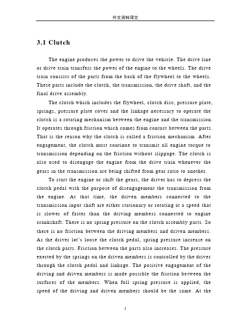
3.1 ClutchThe engine produces the power to drive the vehicle. The drive line or drive train transfers the power of the engine to the wheels. The drive train consists of the parts from the back of the fl ywheel to the wheels. These parts include the clutch, the transmission, the drive shaft, and the final drive assembly.The clutch which includes the flywheel, clutch disc, pressure plate, springs, pressure plate cover and the linkage necessary to operate the clutch is a rotating mechanism between the engine and the transmission. It operates through friction which comes from contact between the parts. That is the reason why the clutch is called a friction mechanism. After engagement, the clutch must continue to transmit all engine torque to transmission depending on the friction without slippage. The clutch is also used to disengage the engine from the drive train whenever the gears in the transmission are being shifted from gear ratio to another.To start the engine or shift the gears, the driver has to depr ess the clutch pedal with the purpose of disengagement the transmission from the engine. At that time, the driven members connected to the transmission input shaft are either stationary or rotating at a speed that is slower of faster than the driving membe rs connected to engine crankshaft. There is no spring pressure on the clutch assembly parts. So there is no friction between the driving members and driven members. As the driver let’s loose the clutch pedal, spring pressure increase on the clutch parts. Friction between the parts also increases. The pressure exerted by the springs on the driven members is controlled by the driver through the clutch pedal and linkage. The positive engagement of the driving and driven members is made possible the friction be tween the surfaces of the members. When full spring pressure is applied, the speed of the driving and driven members should be the same. At themoment, the clutch must act as a coupling device and transmit all engine power to the transmission, without slipping.However, the transmission should be engaged to the engine graduall y in order to operate the car smoothly and minimize tensional shock on the drive train because an engine at idle just develop little power. Otherwise, the driving members are connecte d with the driven members too quickly and the engine would be stalled.The fl ywheel is a major part of the clutch. The flywheel mounts to the engine’s crankshaft and transmits engine torque to the clutch assembly. The flywheel, when coupled with the clutc h disc and pressure plate makes and breaks the flow of power the engine to the transmission.The flywheel provides a mounting location for the clutch assembly as well. When the clutch is applied, the fl ywheel transfers engine torque to the clutch disc. Because of its weight, the fl ywheel helps to smooth engine operation. The flywheel also has a large ring gear at its outer edge, which engages with a pinion gear on the starter motor during engine cranking.The clutch disc fits between the fl ywheel and the pressure plate. The clutch disc has a splinted hub that fits over splints on the transmission input shaft. A splinted hub has grooves that match splints on the shaft. These splints fit in the grooves. Thus, the two parts held together. However, back – and – forth movement of the disc on the shaft is possible. Attached to the input shaft, the disc turns at the speed of the shaft.The clutch pressure plate is generall y made of cast iron. It is round and about the same diameter as the clutch disc. One side of the pressure plate is machined smooth. This side will press the clutch disc facing are against the flywheel. The outer side has shapes to facilitate attachment of spring and release mechanism. The two primary t ypes of pressure plate assemblies are coil sp ring assembly and diaphragm spring.In a coil spring clutch the pressure plate is backed by a number of coil springs and housed with them in a pressed –steed cover bolted to the flywheel. The spring pushes against the cover. Neither the driven plate nor the pressure plate is connected rigidl y to the flywheel and both can move either towards it o away. When the clutch pedal is depressed a thrust pad riding on a carbon or ball thrust bearing is forced towards the flywheel. Levers pivoted so that they engage with the thrust pad at one end and the pressure plate tat the other end pull the pressure plate back against its springs. This releases pressure on the driven plate disconnecting the gearbox from the engine.Diaphragm spring pressure plate assemblies are widely used in most modern cars. The diaphragm spring is a single thin sheet of metal which yields when pressure is applied to it. When pressure is removed the metal spring back to its original shape. The center portion of the diaphragm spring is slit int o numerous fingers that act as release levers. When the clutch assembly rotates with the engine these weights are flung outwards by centrifugal plate and cause the levers to press against the pressure plate. During disengagement of the clutch the fingers are moved forward by the release bearing. The spring pivots over the fulcrum ring and its outer rim moves away from the flywheel. The retracting spring pulls the pressure plate away from the clutch plate thus disengaging the clutch.When engaged the release bearing and the fingers of the diaphragm spring move towards the transmission. As the diaphragm pivots over the pivot ring its outer rim forces the pressure plate against the clutch disc so that the clutch plate is engaged to flywheel.The advantages of a diaphragm t ype pressure plate assembl y are its compactness, lower weight, fewer moving parts, less effort to engage, reduces rotational imbalance by providing a balanced force around the pressure plate and less chances of clutch slippage.The clutch pedal is connected to the disengagement mechanismeither by a cable or, more commonly, by a hydraulic s ystem. Either way, pushing the pedal down operates the disengagement mechanism which puts pressure on the fingers of the clutch diaphragm via a release bearing and causes the diaphragm to release the clutch plate. With a hydraulic mechanism, the clutch pedal arm operates a piston in the clutch master cylinder. This forces hydraulic fluid through a pipe to the cutch release cylinder where another operates the c lutch disengagement mechanism by a cable.The other parts including the clutch fork, release bearing, bell –housing, bell housing cover, and pilot bushing are needed to couple and uncouple the transmission. The clutch fork, which connects to the linkage, actually operates the clutch. The release bearing fits between the clutch fork and the pressure plate assembly. The bell housing covers the clutch assembly. The bell housing cover fastens to the bottom of the bell housing. This removable cover allows a me chanic to inspect the clutch without removing the transmission and bell housing. A pilot bushing fits into the back of the crankshaft and holds the transmission input shaft.3.2 Brake SystemThe breaking system is the most important system in cars. If the brakes fail, the result can be disastrous. Brakes are actually energy conversion devices, which convert the kinetic energy (momentum) of the vehicle into thermal (heat). When stepping on the brakes, the driver commands a stopping force ten times as powerfu l as the force that puts the car in motion. The braking system can exert thousands of pounds of pressure on each of the four brakes.The brake s ystem is composed of the following basic components: the “master cylinder” which is located under the hood, and is directl yconnected to the brake pedal, converts driver foot’s mechanical pressure into hydraulic pressure. Steel “brake lines” and flexible “brake hoses” connect the master cylinder to the “slave cylinders” located at each wheel. Brake fluid, speciall y designed to work in extreme condition, fills the system. “Shoes” and “Pads” are pushed by the salve cylinders to contact the “drum” and “rotors” thus causing drag, which (hopefull y) slows the car.The typical brake system consists of disk brakes in front and either disk or drum brakes in the rear connected by a system of tubes and hoses that link the brake at each wheel to the master cylinder.Stepping on the brake pedal, a plunger is actually been pushing against in the master cylinder which forces hydr aulic oil (brake fluid) through a series of tubes and hoses to the braking unit at each wheel. Since hydraulic fluid (or any fluid for that matter) cannot be compressed, pushing fluid through a pipe is just like pushing a steel bar through pipe. Unlike a s teel bar, however, fluid can be directed through many twists and turns on its way to its destination, arriving with the exact same motion and pressure that it started with. It is very important that the fluid is pure liquid and that there is no air bubbles in it. Air can compress which causes sponginess to the pedal and severely reduced braking efficiency. If air is suspected, then the system must be bled to remove the air. There are “bleeder screws” at each wheel and caliper for this purpose.On disk brakes, the fluid from the master cylinder is forced into a caliper where it pressure against a piston. The piton, in-turn, squeezes two brake pads against the disk (rotor) which is attached to the wheel, forcing it to slow down or stop. This process is simila r to the wheel, causing the wheel to stop. In either case, the friction surface of the pads on a disk brake system, on the shoes on a drum brake convert the forward motion of the vehicle into heat. Heat is what causes the friction surfaces (lining) of the pads and shoes to eventually wear out andrequire replacement.Brake fluid is special oil that has specifics properties. It is designed to withstand cold temperatures without thickening as well as very high temperatures without boiling. (If the brake flui d should boil, it will cause you to have a spongy pedal and the car will be hard to stop).The brake fluid reservoir is on top of the master cylinder. Most cars today have a transparent reservoir so that you can see the level without opening the cover. Th e brake fluid lever will drop slightl y as the brake pads wear. This is a normal condition and no cause for concern. If the lever drops noticeabl y over a short period of time or goes down to about two thirds full, have your brakes checked as soon as possible. Keep the reservoir covered expect for the amount of time you need to fill it and never leave a can of brake fluid uncovered. Brake fluid must maintain a very high boiling point. Exposure to air will cause the fluid to absorb moisture which will lower th at boiling point.The brake fluid travels from the master cylinder to the wheels through a series of steel tubes and reinforced rubber hoses. Rubber hoses are onl y used in places that require flexibility, such as at the front wheels, which move up and dow n as well as steer. The rest of the system uses non-corrosive seamless steel tubing with special fittings at attachment points. If a steel line requires a repair, the best procedure is to replace the complete line. If this is nit practical, a line can be repaired using special splice fittings that are made for brake system repair. You must never use brass “compression” fittings or copper tubing repair a brake system. They are dangerous and illegal.3.2.1 Other Components in the Hydraulic System Proportioning Valve or Equalizer ValveThese valves are mounted between the master cylinder and the rear wheels. They are designed to adjust the pressure between the front and the rear brakes depending on how hard you are stopping. The shorter you stop, the mor e of the vehicle’s weight is transferred to the front wheels, in some cases, causing the rear to lift and the front to dive. These valves are designed to direct more pressure to the front and less pressure to the harder you stop. This minimizes the chance of premature lockup at the rear wheels.Pressure Differential ValveThis valve is usually mounted just below the master and is responsible for turning the brake warning light on when it detects a malfunction. It measures the pressure from the two sections of the master cylinder and compares them. Since it is mounted ahead of the proportioning or equalizer valve, the two pressures it detects should be equal. If it detects a difference, it means that there is probably a brake fluid leak somewhere in the syst em.3.1 离合器发动机产生动力来驱动汽车,它通过传动系把动力传递到车轮上,传动系包含从飞轮到车轮的所有零件。
天机传动天机传动
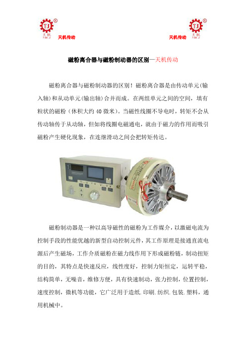
磁粉离合器与磁粉制动器的区别—天机传动
磁粉离合器与磁粉制动器的区别!磁粉离合器是由传动单元(输入轴)和从动单元(输出轴)合并而成。
在两组单元之间的空间,填有粒状的磁粉(休积大约40微米)。
当磁性线圈不导电时,转矩不会从传动轴传于从动轴,但如将线圈电磁通电,就由于磁力的作用而吸引磁粉产生硬化现象,在连继滑动之间会把转矩传达。
磁粉制动器是一种以高导磁性的磁粉为工作媒介,以激磁电流为控制手段的性能优越的新型自动控制元件,其工作原理是接通直流电源后产生磁场,工作介质磁粉在磁力线作用下形成磁粉链,制动扭矩的目的,其特点是快速反应,线性度好,控制力矩恒定,运转平稳,结构简单,无噪音,维修方便,具有快速制动,张力控制,位置控制,速度控制,微机等功能,它广泛用于造纸.印刷.纺织.包装.塑料,通用机械中。
天机传动天机传动
磁粉离合器与磁粉制动器的区别!磁粉离合器和磁粉制动器都是以磁粉为工作介质,以激磁电流为控制手段,达到控制制动或传递转矩的目的。
其输出转矩与激磁粉电流呈良好的线性关系而与转速或滑差无关,并具有响应速度快,结构简单的优点。
所以磁粉制动器的选型一般以所需传达最大转矩为依据来选定,并同时注意保证实际滑差功率小于磁粉离合器、制动器的允许滑差功率。
由天机传动提供。
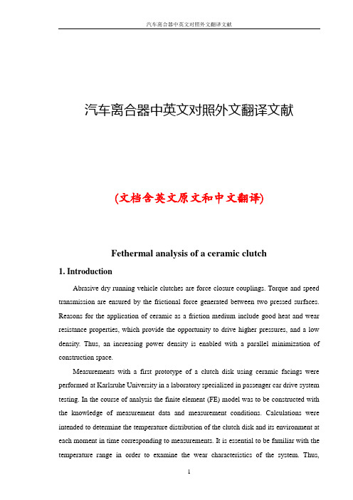
汽车离合器中英文对照外文翻译文献(文档含英文原文和中文翻译)Fethermal analysis of a ceramic clutch1. IntroductionAbrasive dry running vehicle clutches are force closure couplings. Torque and speed transmission are ensured by the frictional force generated between two pressed surfaces. Reasons for the application of ceramic as a friction medium include good heat and wear resistance properties, which provide the opportunity to drive higher pressures, and a low density. Thus, an increasing power density is enabled with a parallel minimization of construction space.Measurements with a first prototype of a clutch disk using ceramic facings were performed at Karlsruhe University in a laboratory specialized in passenger car drive system testing. In the course of analysis the finite element (FE) model was to be constructed with the knowledge of measurement data and measurement conditions. Calculations were intended to determine the temperature distribution of the clutch disk and its environment at each moment in time corresponding to measurements. It is essential to be familiar with the temperature range in order to examine the wear characteristics of the system. Thus,important information is derived from measurement data. In critical load cases, the highest expected temperatures must be forecast in space and time in order to protect measuring instruments close to the location of heat generation.The goal of this study is to analyze and modify the clutch system to provide better operating conditions by improving the heat conduction and convection of the system or to increase the amount of the energy converted into frictional heat. Furthermore, it is desired to find better design solutions for more efficient clutch systems.Calculations were performed by the Cosmos Design Star software. During model development, great care had to be taken for proper simplification of geometry, the selection of element sizes, and the correct adjustment of time steps due to the substantial hardware requirements for transient calculations. Changes in thermal parameters such as the surface heat convection coefficient and thermal load had to be taken into consideration on an on-going basis in terms of time and location. The two sides of the analyzed test clutch system can only be managed by two independent models linked by heat partition, according to the hypothesis that the contact temperature must be identical on both sides while there is proper contact between them and its value must be adjusted by iteration. Calculations revealed that the heat partition changed by cycle and it differed along the inner and outer contact rings. As a result of the different cooling characteristics between the ceramic and steel side, a heat flow is launched from the ceramic side to the steel side. This heat flow was also determined by iteration, its value also changes by cycle and differs along the inner and outer contact rings.2. First prototype of a clutch using engineering ceramics as friction materialThe examined clutch disk was developed according to the “specific ceramic” product development process established at the Institute for Product Development (IPEK) at the University of Karlsruhe. This development process already has the possibility for connection to a real transmission shaft; further, it has a cushion spring device for the facings allowing good start behaviour. Abrasive clutches must comply with the following basic requirements:●high torque transmission according to high friction coefficients,●high comfort (no vibrations through self-induced chattering),●homogeneous temperature distribution,●low wear characteristic.A critical element of the switch is the abrasive disk.With regard to the design utmost care must be taken to select the right material. A high and constant friction coefficient,,wear resistance and thermal resistance are desired characteristics. The clutch disk has instead of the generally applied ring-shaped abrasive inlet two rows of SSIC (as sintered) ceramic pellets. These pellets are placed on 6 separate segments. The segments are fixed to the central hub by rivets. Each segment consists of 4 plates, 2 working as facing springs and 2 as carriers.3. MeasurementsMeasurements were performed at the department of power train development of the Institute for Product Development (IPEK) at the Karlsruhe University (TH) Research University, where a category IV component test rig is used for tests of new frictional materials and examinations of new materials in real clutch disks. Real conditions are applied by the simulation of driving resistance (e.g. starting in the plane, starting at the hill). It is a component test rig leveled on the fourth position of the tribological testing environment.In order to give an idea of dimensions: the equipment length is about 4-5m. The two electric motors and the axial force are controlled independently by computer; thereby many operational states can be realized. This enables the equipment to complete a myriad of tribological measurements all while properly modeling the operation of a clutch disk in a passenger car. It is also equipped with an automatic IT measurement system. Measurable quantities include the following:●two heavy-duty electric motors (150 KW, Baumuller DS 160L-305),●device suitable for exerting axial force,●torque meter (Manner Sensortelemetrie MF100),●axial force meter,●steel disk in friction,●replaceable head to affix the device to be tested,●temperature along two different radii at 0.4mm below the abrasive surface of the steeldisk (Omega HJMTSS-IM100U-150-2000,J-typeiro-constantan thermocouples),●revolutions per minute for both sides (Polytene LSV 065).The greatest challenge out of these is temperature measurement as we would like to know the temperature of the revolving steel disk. The two thermoelements placed in the steel disk forward data to the computer through a wireless blue tooth system and are placed 0.4mm below the abrasive surface of the steel disk on the two opposite arcs of the clutch disk.3.2. Measurement processDue to component analyses and cost reduction only one side of the clutch disk is mounted with ceramic facings. Thus, the clutch disk and its fitting will be referred to as the ceramic side, and the abrasive steel disk with its environment revolving together will be referred to as the steel side. In the course of measurements, data were collected at a sampling frequency of 100 and 1000HZ. Measurements were conducted according to the time curves.The measurement starts by increasing the revolutions per minute of the steel side (the driving side) to a specific value (1500 rpm here). Then the ceramic side (the driven side), held at zero rpm, is pushed towards the steel disk and the axial force is applied until a designated value is reached (nominally 4200N here). Upon reaching the designated axial force the ceramic side is released and the two sides start to synchronize. A few seconds after synchronization, the axial load is discontinued and after some time both the steel and the ceramic sides—revolving at the same speed—are slowed down. This is deemed to be one measurement cycle. Ten cycles are completed in the course of a single measurement. During application of the axial force the ceramic side is held at zero rpm until the desired force is reached to ensure synchronization occurs at nearly the same time of each cycle. This is unfavorable from the viewpoint of both measurements and calculations. Measurements are usually conducted by changing only 3 parameters: the speed, the axial load and the inertia. The following figures are applied in various combinations:●speed n: 700, 1100 and 1500 (rpm),●axial force F: 4200, 6400 and 8400 (N) andinertia I: 1, 1.25 and 1.5 (kgm2).Experimental measurements are launched with approx.10-15 min intervals, during which the system cools down to about 30-40 1C. This makes calculations difficult, as the exact temperature distribution of the system is not known at the commencement of the measurement. However, it can be assumed that a period of 10-15min is sufficient for a nearly homogeneous temperature distribution to be produced. The parameters for the following simulation have been chosen for an intermediate case with a speed n =1500 rpm, an axial force F = 4200 N and an inertia I = 1 kg m2.4. Calculations of heat generationThe mechanical energy consumed during the friction of two bodies is transformed into heat. The generated heat can be calculated by the following simple formula: Q =μ·ν·F [W] .where m is the the frictional coefficient; v is the sliding velocity; F is the force perpendicularly compressing the surfaces. And the heat flux density per surface unit is q=μ·ν·p [Wm2].where p is the the pressure calculated as a ratio of the force and the contacting surface. As the ceramic tablets are placed at two different radii along the clutch disk, the heat generated must be calculated separately for each radii. Sliding can be divided into two sections. In the first section, the ceramic side is kept in a stationary position by braking, meanwhile the axial load is increased; therefore compression changes in the course of time while the speed difference between the two sides is constant. In the second section (at synchronization) the speed difference is equalized while the force value is constant, so velocity changes in time. On the basis thereof, the heat generated is.The nominal contact area is the aggregate of the contacting surfaces of the 24 and 18 ceramic tablets on the given ring. The diameter of ceramic tablets is:.Calculations were performed for the load case to be characterized by the following parameters:.Based on experimental measurements a constant friction coefficient of 0.4 was established..The velocity can be calculated with the knowledge of the radius and the speed..Surface pressure can be calculated as a ratio of the axial force and the contacting surface. This produces the same figure for each ceramic pellet, assuming an even load distribution..Thus, the maximum values of the generated heat are.In the first section of sliding, the generated heat is rising due to the increase of the load force; in the second section, it is decreasing due to the equalization of the speed difference. It is necessary to know the time of each sliding section in order to be able to specify the generated heat time curve. These can be determined from measurement dataseries. Synchronization time can be easily determined from the speed of the ceramic side. Speed increase is linear. Force increase is non-linear. For the sake of simplicity, force increase was substituted by a straight line in calculations so that the area below the straight line is nearly identical with the area measured below the curve. Thus, the time difference between the two terminal points of the straight line is the time of the first sliding section.The above-mentioned method was applied for each cycle and their average was specified. Based on these results, the following values were determined for sliding times:.Now the time curve of heat generation can be produced. The same curve was used in each cycle as there were no significant differences between parameters in each cycle. The generated heat-calculated this way-will appear as thermal load in the thermal model. It must be distributed appropriately between the contacting surfaces by taking into consideration heat partition. Heat partition requires the contact temperatures to be identical at both surfaces. Correct adjustment requires repeated iterations.有限元热分析的陶瓷离合器1 引言磨料空转车辆离合器是力封闭联轴器。

附录How Does the Clutch WorkThe clutch is a device to engage and disengage power from the engine, allowing the vehicle to stop and start.A pressure plate or “driving member” is bolted to the engine flywheel, and a clutch plate or “driven member” is loc ated between the flywheel and the pressure plate. The clutch plate is spline to the shaft extending from the transmission to the flywheel, commonly called a clutch shaft or input shaft. When the clutch and pressure plates are locked together by friction, the clutch shaft rotates with the engine crankshaft. Power is transferred from the engine to the transmission, where it is routed through different gear rations to obtain the best speed and power to start and keep the vehicle moving.The flywheel is located at the rear of the engine and is bolted to the crankshaft. It helps absorb power impulses, resulting in a smoothly-idling engine and provides momentum to carry the engine through its operating cycle. The rear surface of the flywheel is machined flat and the clutch components are attached to it. The driving member is commonly called the pressure plate. It is bolted to the engine flywheel and its main purpose is to exert pressure against the clutch plate, holding the plate tight against the flywheel and allowing the power to flow from the engine to the transmission. It must also be capable of interrupting the power flow by releasing the pressure on the clutch plate. This allows the clutch plate to stop rotating while the flywheel and pressure plate continues to rotate.The pressure plate consist of a heavy metal plate, coil springs or diaphragm spring, release levers (fingers), and a cover. When coil springs are used, they are evenly spaced around the metal plate and located between the plate and the metal cover. This places an even pressure against the plate, which in turn presses the clutch plate tight against the flywheel. The cover is bolted tightly to the flywheel and the metal pate is movable, due to internal linkages. The coil springs are arranged to exert direct or indirect tension on the metal plate, depending upon the manufacturer’s design. Three release levers (fingers), evenly spaced around the cover, are used on most pressure plates to release the holding pressure of the springs on the clutch plate, allowing it to disengage the power flow.When a diaphragm spring is used instead of coil springs, the internal linkage is necessarily different to provide an “over-center” action to release the clutch plate from the flywheel. Its operation can be compared to the operation of an oilcan. When depressing the slightly curved metal on the bottom of the oilcan, it goes over-center and gives out a loud “clicking” noise; when released, the noise is again heard as the metal returns to its originalposition. A click is not heard in the clutch operation, but the action of the diaphragm spring is the same as the oilcan.The clutch plate or driven member consists of a round metal plate attached to a splined hub. The outer portion of the round plate is covered with a friction material of molded or woven asbestos and is riveted or bonded to the plate. The thickness of the clutch plate and /or facings may be warped to give a softer clutch engagement. Coil springs are often installed in the hub to help provide a cushion against the twisting force of engagement. The splined hub is mated to (and turns) a splined transmission shaft when the clutch is engaged.The release (throw out) bearing is usually a ball bearing unit, mounted on a sleeve, and attached to the release or throw out lever. Its purpose is to apply pressure to the diaphragm spring or release levers in the pressure plate. When the clutch pedal is depressed, the pressure of the release bearing or lever actuates the internal linkages of the pressure plate, releasing the clutch plate and interrupting the power flow. The release bearing is not in constant contract with the pressure plate. A linkage adjustment clearance should be maintained.The clutch pedal provides mechanical means for the driver to control the engagement and disengagement of the clutch. The pedal is connected mechanically to either a cable or rods, which are directly connected to the release bearing lever.When the clutch pedal is depressed, the linkage moves the release bearing lever. The release lever is attached at the opposite end to a release bearing which straddles the transmission clutch shaft, and presses inward on the pressure plate gingers or the diaphragm spring. This inward pressure acts upon the fingers and internal linkage of the pressure plate and allows the clutch plate to move away from the flywheel, interrupting the flow of power.While the clutch pedal is depressed and the power flow interrupted, the transmission can be shifted in to any gear. The clutch pedal is slowly released to gradually move the clutch pate toward the flywheels under pressure of the pressure plate springs. The friction between the clutch plate and flywheel becomes greater as the pedal is released and the engine speed increased. Once the vehicle is moving, the need for clutch slippage is lessened, and the clutch pedal can be fully released.Coordination between the clutch pedal and accelerator is important to avoid engine stalling, shock to the driveline components and excessive clutch slippage and overheating.离合器如何工作离合器是传递和分离发动机动力的装置,实现车辆的停车和启动。

磁粉离合器磁粉成分
磁粉离合器是一种利用磁性粉末传递扭矩的装置,通常用于传
动系统中。
磁粉离合器的磁粉成分通常包括铁粉、磁性材料和粘结剂。
铁粉是磁粉离合器中的主要成分,它具有良好的导磁性能和磁
导率,能够在磁场作用下产生磁化现象。
磁性材料通常是指氧化铁、铝酸铁等,它们能够增强磁粉的磁性能,提高磁粉离合器的传递效
率和扭矩传递能力。
粘结剂则是将磁性材料和铁粉牢固地粘结在一起,形成坚固的磁粉结构,同时也有助于磁粉离合器的制造加工和
稳定性。
总的来说,磁粉离合器的磁粉成分是经过精心配比和加工
制备的复合材料,具有良好的磁性能和传递特性,能够在传动系统
中发挥重要作用。
专利名称:磁粉离合器
专利类型:实用新型专利
发明人:吕小勇
申请号:CN200920264886.5申请日:20091217
公开号:CN201606426U
公开日:
20101013
专利内容由知识产权出版社提供
摘要:本实用新型涉及生活用品技术领域,特指磁粉离合器,其转轴外部套设有相互对接的一号内套、二号内套,一号内套、二号内套的外部设有相互对接的一号外壳、二号外壳,转轴的两端与一号内套、二号内套之间分别设有一号滚动轴承,一号外壳与二号内套、二号外壳与一号内套之间分别设有二号滚动轴承,一号滚动轴承、二号滚动轴承外部设有一号卡簧、二号卡簧,一号外壳、二号外壳、一号内套、二号内套之间结合部设有激磁线圈,转轴上套设有密封圈,密封圈与一号内套、二号内套的内壁形成磁粉室,其结构设计科学简单,体积小、使用安装方便,可多方位安装,不受位置限制。
申请人:吕小勇
地址:523400 广东省东莞市寮步镇新旧围莞樟路良平段135号
国籍:CN
更多信息请下载全文后查看。
磁粉离合器的工作原理
磁粉离合器是一种利用磁性粉末来传递转矩的装置。
它由一个外部壳体、一个传动轴和磁粉组成。
磁粉离合器的工作原理如下:当电流通过离合器的电磁线圈时,产生一个磁场。
这个磁场使得磁性粉末充满整个离合器的空腔,并将磁粉转化为一个刚性的传递介质。
当外部轴与传动轴连接时,磁粉将会沿着磁场方向传递转矩。
传动轴的转动会产生摩擦力,使得离合器的输出轴开始旋转。
当电流通过电磁线圈停止时,磁场消失,磁粉由于自身的黏性停止转动。
这导致外部轴和传动轴之间断开转矩传递,离合器的输出轴停止旋转。
磁粉离合器的工作可被称之为“开关型离合器”,因为它的工作状态可以通过电流的开关来控制。
总的来说,磁粉离合器通过磁性粉末的变化来传递转矩。
当电流通过电磁线圈时,磁性粉末成为一个刚性传递介质,使得离合器转动。
停止电流,磁粉则失去刚性,离合器停止转动。
这种工作原理使得磁粉离合器具有可控和可靠的性能。
磁粉离合器的用途
磁粉离合器是一种常见的传动装置,其主要用途是传递动力和控制转速。
磁粉离合器采用磁性粉末作为阻力元件,当磁场通入时磁性粉末便会产生阻力,阻碍转速的传递,从而实现传动的控制。
具体来说,磁粉离合器主要应用于以下几个方面。
1. 用于工业机械传动
磁粉离合器广泛应用于各种工业机械传动中,如冶金、矿山、造纸、橡胶、纺织、印刷等行业。
在机械传动中,磁粉离合器作为一种精确可靠的控制元件,能够保证机械的稳定运转及精确定位,提高机械的工作效率。
2. 用于汽车离合器
磁粉离合器也被广泛应用于汽车离合器中。
现代汽车中的磁粉离合器通常使用永磁体来激励磁性粉末,这种离合器具有快速响应、平稳的离合特性和高效的能耗等优点,能够提高汽车的燃油效率,降低车辆的排放。
3. 用于半自动机床
磁粉离合器还被广泛应用于半自动机床中,如钻床、铣床、车床等。
在机床传动
中,磁粉离合器能够控制工件的加工过程,提高机械设备的精度和稳定性,减少失误和人为的误差。
4. 用于液压泵、风扇和动力传动系统
磁粉离合器还可以应用于液压泵、风扇和动力传动系统等领域。
在这些领域中,磁粉离合器通常用于控制转速和扭矩,实现运动过程的平稳、准确和可控,提高设备的稳定性和效率。
总之,磁粉离合器作为一种重要的传动装置,被广泛应用于工业、汽车、机床、液压泵和风扇等领域,为设备的正常运转和工作效率提供了可靠的保障。
附录AStick to the car, clutch is an important component of the auto power system, it bears will power and the engine cut and connection between the work. In urban road sections or complex, our most frequently used clutch became one of the components, and clutch, use directly reflects the driving of level, but also reflects the good protection for vehicles. Used correctly, principle of clutch clutch in special circumstances using clutch to solve problems, each block is driving the car manual should master enthusiasm.So-called clutch, just as its name implies is using "from" and "close" to deliver the amount of power. By friction clutch, shrapnal, pressure plate and dynamic output shaft, decorate in the engine and transmission between, used to be the flywheel storage engine torque to gearbox, ensure vehicles in different driving conditions apply to drive wheels, belong to the driving force and torque powertrain category. In half the time of the clutch, linkage power input and output power is allowed, namely through rotational speed to realize the amount of power transmission.The clutch is divided into three working condition, not on the clutch type on the part of the clutch, under half step down, and the type of clutch type. When the vehicle in normal operation, the pressure plate is tightly packed on the friction of friction, pressure plate and the friction between the biggest slice, input shaft and the output shaft remains relatively static frictionbetween both speed and in the same. When the vehicle, the driver started on the clutch pedal, clutch platen movement by pulling back, also is the pressure plate and friction slices, pressure plate and the separation of the flywheel no contact will not exist relatively friction.Finally, also is a type of clutch. At this time, the pressure plate and the friction in small type. Clutch disc friction slices with flywheel is sliding friction between state. The flywheel speed than the output shaft speed, the power transmission from the flywheel part to the gearbox. This engine and driving wheel is equivalent to a soft connection between state.Generally speaking, the clutch is started and shift in vehicles, at the time of transmission shaft and a second shaft rotation difference exists between the power of the engine, must be with a shaft cut, can be very good synchronizer will keep a shaft speed and synchronous, block into later, again with a shaft through clutch of engine power, power continue to transmit.In the clutch, and an indispensable buffering device, it consists of two similar to the flywheel disc disc playing together, in rectangular groove is decorated in the slots in the spring, the impact of fierce encounter between the two disks, spring, mutual happen elastic cushion external stimuli. Effective protection of engine and clutch. In all parts of the clutch platen, intensity of spring, the friction coefficient, clutch friction, diameter and clutch position number is the key factor decision clutch performance, the stiffness of hydropneumatic spring, the friction coefficient is higher, the diameter of theclutch, clutch performance is better.When beginning to have time, to ensure the linkage of half started smoothly. Sit novice car have such experience, or remove, or started a quiver yishan, these are not good skills and linkage. The car at the start of the second shaft, gearbox, when we are still hang a block, need on the clutch, a transmission axis and power, through the synchronizer hang a block, a shaft also become motionless. Power is out from the flywheel, there must be a rotating shaft with great speed, which is why started to half of requirements than the shift much when the main reason, clutch before a stationary components, a movement.So the speed of the poor by half linkage to digest must, is at the beginning of the power transmission shaft, and give a part of the vehicle to a smooth start posture, once the vehicle, speed difference will become small, at this time will clutch, there won't be fully up the impact.Start to higher ramps and linkage skills. Half the speed and the engine can be digested linkage between the wheel speed difference, i.e., the power can be passed to the wheel, but not running wheel, which often occurred in the ramp. General for driving technology not skilled driver, start up the ramp when handbrake, then let the clutch is linkage, panasonic, vehicle handbrake stationary car after disaster prevention, slip. The gravity of the slide backwards and vehicle by the engine is the power to provide against, and clutch is responsible for eliminating the speed difference exists here.Vehicles in this kind of circumstance, the driver can easily start, continue to trample accelerator pedal to obtain enough to further improve speed of torsion, vehicle goes up the slope. Now the skills required for half a linkage, if half linkage too weak, might efforts in the open hand brake when slide backwards, easy to cause the vehicle's panic, if half of a joint efforts, easy is accelerating and hit limber fast-drawing. So for beginners, can let the engine speed slightly tall, and the greater half linkage, make vehicles have a walk when the trend, and loosen the handbrake.When will the novice driving some mistakes on the use of the clutch. As a novice, due to driving technology, it will be difficult to unskilled oil from good coordination, resulting in use when the clutch of some beneath the clutch, and these operating methods are also appeared in the half of time.Avoid clutch at half time state can effectively protect the linkage of clutch. Some of the novice just when due to stress, oil from bad cooperation and started out in the car, then remove and clutch shot big throttle pressure very low, but also don't lift realize all along, the linkage of engine speed and a shaft rotational speed of the huge, and vehicle speed is slowly started, the great speed of all poor by clutch linkage, this is very destroyed digestion. Clutch, In order to avoid using the ramp frequent trample brake, so half feet in half the speed KongZhiChe linkage to, or a clutch. FrowstyThe whole process of sliding friction clutch occurs, the long time of sliding friction will damage the clutch. Driving on the left foot in general likethe clutch not consciously, resulting in the clutch pedal under pressure for a long time, the vehicles at half linkage. All of these operations can accelerate the clutch disc wear, the dynamic performance and fuel economy of vehicle can cause damage.The clutch is a frequent automobile parts of the friction over time, it will be increased frequency of use and wear, and can produce clutch skid phenomenon. For experienced pilots can be found, such as advance whether we can judge the clutch in situ skidding car when a block, then hang soonly, and then slowly lift clutch brake up until completely, if the clutch lift, engine flameout this proof of your clutch not sliding, anyway if the clutch is completely lift and car is not leaving the clutch is proof that you.There is in start when suddenly felt clutch position, also the clutch, another is the precursor of sliding speed in urgent when we just feel engine speed in rising, and speed, but not all of these conditions are signs of sliding clutch. When the clutch when we want to wear or skid timely inspection, replacement, otherwise will make the engine output power can effectively to the output shaft, but will power loss in the clutch plate and the sliding friction between the flywheel, and the friction between energy consume, for it will cause power transmission, also dues increase the cost of oil transport.附录B对于手动挡的车型而言,离合器是汽车动力系统的重要部件,它担负着将动力与发动机之间进行切断与连接的工作。
磁粉离合器的外文资料 默认分类 2011-05-04 10:57:37 阅读1 评论0 字号:大中小 订阅 磁粉离合器Magnetic powder clutch is combined with the transmission unit (input axis) and driven unit (output axis). The space between the two groups of unit is filled with some granular magnetic powder (volume about 40 microns). When solenoids don’t conduct electricity, torque can’t work between drive shaft and driven shaft. But when the coils are power on by electromagnetic, it will attract magnetic powder and cause sclerosis phenomenon by magnetic force. Then torque will be transmitted by sliding.
Magnetic powder clutch is a kind of the superior performance of automatic control components. We take magnetic powder as the working medium and magnetizing current as the control measure to achieve braking control and torque transmission. Its output torque has fine linear relation with magnetizing, but has nothing to do with speed and slid. it is characterized by rapid response speed and *** structure. It is widely used in tension automatic control systems of wire, cable, packaging, printing, *** and *** processing, textiles, rubber, leather, metal foil tape processing and other relevant coiling device. Magnetic powder clutch is also used in the buffer starting, overload protection, speed switch, etc.
(1) high-precision torque control The torque can achieve high precision control and wide control range through conveying torque and exciting current into the right proportion.
(2) excellent durability and long service life Magnetic powder clutch has long service life by using heat resistance, abrasion resistance, resistance to oxidation and corrosion resistance super ultra alloy powder.
(3) stable constant torque characteristics Magnetic powder has magnetosphere characteristics, and the adhesion between particles is quite. Sliding torque is very stable, and the relative rotation several no relationship can abiding constant torque.
(4) continuous sliding operation use Magnetic powder clutch has good heat dissipation and uniform cooling structure of thermal deformation. Then high heat resistance of magnetic powder allows links and braking power and sliding high power, can smooth sliding operation, and won't cause vibrations. (5) link smooth, non-impact There is no impact when it links. It can start and stop smoothly non-impact. And resistance torque is tiny and won't cause useless calorific value.
(6) suitable for high frequency operation It is suitable for high frequency operation use with quick response and special quick cooling structure,
(7) lightweight, maintenance-free, long service life It is lightweight using concise type of high-temperature coil and special grease bearings. And imposing wear-resisting attrition easily armature special treatment can prolong service life.
Edit features of the product 1. Magnetic powder clutch and brake is a kind of the superior performance automatic control components
2. It is with high linear and high-precision torque control. 3. It uses high temperature resistant coil super alloy powder and can prolong service life. It is smooth in connection and there is non-impact magnetic particle clutch.
4. The product of high precision, the careful treatment, excellent linearity, superior performance is made by CNC precision manufacturing.
5. Magnetic powder is high purity without black carbon powder and stable performance with long service life .
6. The aluminum-alloy structure is with excellent thermal performance, good retreat magnetic and fast response.
7. At startup, operation and braking condition, it works smoothly without vibration, shock and noise.
8. As the torque is proportional to and exciting current in the provision of torque range, we can take it as linear regulating elements.
9. Output torque is constant, because torque size just depends on the size of the current excitation and has nothing to do with sliding speed.
10. Parting or gathering is frequent with fast response, higher frequencies and every minute can achieve 40 to 60 times. It can be widely applied in rapid working status and high frequency occasion.
11. With high power magnification, it is easy to achieve automatic control by using small exciting current to control large transmission power.