国巨电阻电容料号
- 格式:ppt
- 大小:103.50 KB
- 文档页数:2
Page-1Approval SheetforCarbon Film ResistorsCFR series±2% & ±5%YAGEO CORPORATIONHeadquarters: 3F, No.233-1, Pao Chiao Rd., Shin Tien, Taipei, Taiwan,R.O.C.Tel: 886-2-2917-7555 Fax: 886-2-2917-4286URL: Page-2Page-31. PRODUCT : CARBON FILM RESISTORS(Normal & Miniature Style)2. PART NUMBER : Part number of the carbon film resistor is identified by the name,power, tolerance, packing, temperature coefficient, special type and resistance value.Example :CFR -12 J T J 52 100RSeries Size Resistance Packing Temperature Special ResistanceName Code Tolerance Style Coefficient Type Value of Resistance(1) Style: CFR SERIES(2) Power Rating: -12=1/6W 、25S=1/4WS 、-25=1/4W 、50S=1/2WS 、-50=1/2W 、 1WS=1WS 、100=1W 、2WS=2WS 、200=2W(3) Tolerance: G=±2% J=±5%(4) Packaging Type : R =Paper Taping Reel T =Tape on Box Packing B =Bulk Packing(5) T .C .R : J=±350ppm/℃ — =lgnore(6) Special Type : 26=26mm 、52=52.4mm 、73=73mm 、 PN =PANAsert AV =AVlsert(7) Resistance Value: 1R 、10R 、100R 、10K 、100K 、330K 、1M………Page-43. BAND-CODE:4. ELECTRICAL CHARACTERISTICSTabe I*Standard resistance is 1Ω~ 10M Ω, below or over this resistance on request. *Rated Continuous Working Voltage (RCWV)=Value Resistance Rating Power ×FIG.1 TEMPERATURE COEFFICIENTPage-55. DERATING CURVE & HOT-SPOT TEMPERATURE6. DIMENSIONS7. ENVIRONMENTAL CHARACTERISTICS(1) Short Time Over Load TestAt 2.5 times of the rated voltage. (If the voltage exceeds the maximum load voltage, the maximum load voltage will be used as the rated voltage) applied for 5 seconds, the resistor should be free from defects after the resistor is released from load for about 30 minutes and the change of the resistance value should be within ±(0.25%+0.05Ω) as compared with the value before the test.Page-6(2) Dielectric Withstanding VoltageThe resistor is placed on the metal V Block. Apply a Table I dielectric withstanding between the terminals connected together with the block for about 60 seconds. The resistor shall be able to withstand without breakdown or flashover.(3) Temperature Coefficient TestTest of resistors above room temperature 125°C to 130°C (Testing Temperature) at the constant temperature silicon plate for over 4 to 5 minutes. Then measure the resistance. The Temperature Coefficient is calculated by the following equation and its value should be within the range of requested.600010t t 1R R R t Coefficien e Temperatur sistor Re ×−×−=R= Resistance value under the testing temperature R 0= Resistance value at the room temperature t = The testing temperature t o = Room temperature(4) Insulation ResistanceApply test terminal on lead and resistor body. The test resistance should be high than 10,000 Mohm.(5) SolderabilityImmerse the specimen into the solder pot at 230±5°C for 5±0.5 seconds. At least 95% solder coverage on the termination.(6) Resistance to SolventThe specimen into the appropriate solvent of Methyleme Chloride condition ofultrasonic machine for 1 minutes. The specimen is no deterioration of coatings and color code.(7) Terminal StrengthDirect Load – Resistors shall be held by one terminal and the load shall be gradually applied in the direction of the longitudinal axis of the resistor unit the applied load reacheds 5 pounds. The load shall be held for 10 seconds. The load of weight shall be ≧2.5kg(24.5N).Page-7(8) Pulse OverloadApply 4 times of rated voltage to the specimen at the 1 second on and 25 seconds off cycle, subjected to voltage application cycles specified in 10000. The change of the resistance value shall be within ±(2%+0.05Ω).(9) Load Life in HumidityPlace the specimen in a test chamber at 40±2°C and 90~95% relative humidity. Apply the rated voltage to the specimen at the 1.5 hours on and 0.5 hour off cycle. The total length of test is 1000 hours. The change of the resistance value shall be within ±(1.5%+0.05Ω).(10) Load Life TestPlaced in the constant temperature chamber of 70±3°C the resistor shall be connected to the lead wire at the point of 25mm. Length with each terminal, the resistors shall be arranged not much effected mutually by the temperature of the resistors and the excessive ventilation shall not be performed, for 90 minutes on and 30 minutes off under this condition the rated D.C. voltage is applied continuously for 1000+48/-0 hours then left at no-load for 1hour, the change of the resistance value measured at this time to the value before the test shall be within ±(1.5%+0.05Ω). There shall be no remarkable change in the appearance and the color code shall be legible after the test.(11) Temperature Cycling TestThe temperature cycle shown in the following table shall be repeated 5 times consecutively. The measurement of the resistance value is done before the first cycle and after ending the fifth cycle, leaving in the room temperature for about 1 hour, the change shall be within ±(1%+0.05Ω). After the test the resistor shall be free from the electrical or mechanical damage.Temperature Cycling Conditions: Step Temperature(°C) Time (minute)1 +25+10 -5 10 to152 -65+0 -3 30 3 +25+10 -5 10 to15 4+150+3 -030Page-8(12) Resistance to Soldering HeatThe terminal lead shall be dipped into the solder pot at 350±10°C for 3±0.5 seconds up to 3 mm. The change of the resistance value shall be within ±(1%+0.05Ω).8. PACKING METHODS Bandolier for Axial leadsThe resistors are supplied on bandolier, either 1000 resistors in ammopack or 5000 resistors on reel.9. TAPE ON REEL PACKING & TAPE ON BOX PACKING10. SPECIAL TYPE (FORMING DIMENSIONS)。
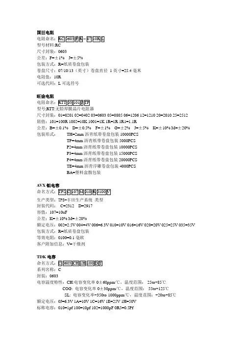
国巨电阻型号材料:RC尺寸封装:0603公差:F=±1% J=±5%包装方式:R=纸质卷盘包装卷盘尺寸:07/10/13(英寸)卷盘直径1英寸=25.4毫米电阻值:10R可选代码:L可选符号旺诠电阻型号;RTT:无铅厚膜晶片电阻器尺寸封装:01=0201 02=0402 03=0603 05=0805 06=1206 12=1210 20=2010 25=2512阻值:101=100R 1002=10K 1001=1K 1R=1R 1R1=1.1R公差:B=±0.1% D=±0.5% F=±1% G=±2% J=±5% K=±10% M=±20%包装形式:TH=2mm沥青纸带卷盘包装10000PCSTP=4mm沥青纸带卷盘包装5000PCSP2=4mm沥青纸带卷盘包装10000PCSP3=4mm沥青纸带卷盘包装15000PCSP4=4mm沥青纸带卷盘包装20000PCSTE=4mm沥青浮雕卷盘包装4000PCSBA=塑料盒散包装A VX钽电容封装代码:C=2312 D=2917容值:107=10uF公差:K=±10% M=±20%额定电压:002=2.5V 004=4V 006=6.3V 010=10V 016=16V 020=20V 025=25V 035=35V 包装方式:R=纸质卷盘包装等效电阻:0100=0.1毫欧客户附加信息:V=干燥剂TDK电容系列名称:C封装:0603电容温度特性:CH:电容变化率0±60ppm/℃,温度范围:-25to+85℃COG: 电容变化率0±30ppm/℃,温度范围:-55to+125℃SL: 电容变化率+350to-1000ppm/℃,温度范围:+20to+85℃额定电压:0J=6.3V 1A=10V 1C=16V 1E=25V 1H=50V标称电容:010=1pf 100=10pf 102=1000pF 0R5=0.5Pf允许误差:C=±0.25pF D=±0.5pF J=±5% K=±10% M=±20% Z=+80pF,-20%包装方式:T=卷盘包装B=散装三星电容系列名称:CL=积层陶瓷电容尺寸编码:03=0201 05=0402 10=0603 14=0504 21=0805 31=1206 32=1210 01=0306 42=1808 43=1812 55=2220 12=0508电容容量编码:105=10 00000pF 3R3=3.3pF电介质编码:A=X5R 其中X= -55℃5= +85℃R= ±15%,描述的是电容的温度特性。


国巨电阻编码规则
国巨电阻的编码规则是以字母和数字的组合为主。
前两个字母表示电阻的系列名称,用于区分不同类型的电阻。
例如,RC表示一般厚膜电阻,RF表示射频电阻,RD表示热敏电阻,RN表示压敏电阻,RT表示高压电阻。
系列名称后面的4位数表示尺寸,例如0100、0201、0402等。
这些数字通常代表电阻的尺寸,如长度和宽度的组合。
此外,国巨电阻的误差以字母表示,具体如下:W=±0.05%,B=±0.1%,C=±0.25%,D=±0.5%,F=±1%,G=±2%,J=±5%,K=±10%,M=±20%。
封装形式一般以字母表示,例如R表示纸带,K表示塑料编带。
数值表示阻值,例如0R表示0欧姆,1K表示1000欧姆。
部分国巨贴片电阻在型号后缀中表示无铅。
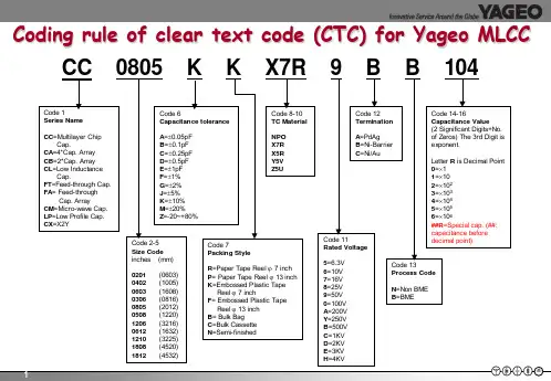
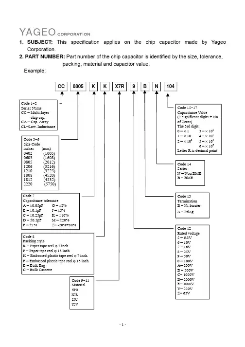
国巨贴片电容知识一、国巨贴片电容的命名:贴片电容的命名所包含的参数有贴片电容的尺寸、容值精度、贴片电容的材质、电压、电容容量、端头材料以及包装要求。
例如:国巨贴片电CC0805JRNPO9BN101容CC:表示国巨电容系列名称——多层陶瓷贴片电容。
国巨电容的系列还有CA(表示排容),CH(表示高频电容)等等。
0805:表示尺寸,长度为0.08英寸,宽度为0.05英寸。
此外,常见的电容尺寸还有0201,0402,0603,1206,1210,1808,1812等。
J:表示电容容量的误差精度为±5%;另外B=±0.1PF,C=±0.25PF,D=±0.5PF,F=±1PF,G=±2PF,K=±10%,M=±20%,Z=-20%~+80%。
R:表示7寸盘纸带包装。
NPO:表示电容材质。
此外,常用的电容材质还有X5R,X7R,Y5V。
9:表示电压为50V。
4=4V, 5=6.3V, 6=10V, 7=16V, 8=25V, 0=100V, A=200V, B=500V, C=1KV, D=2KV, E=3KV等(注意:100V是用数字0表示,不是字母O)B:表示端头材料是镍电极。
N:表示NPO。
101:表示容值,前面两个数字为有效数字,第三个数字表示有几个零。
101=100PF, 102=1000PF, 103=10,000PF……以此类推。
二、英制尺寸与公制尺寸的对应表:TDK贴片电容的参数识别积层贴片陶瓷片式电容器C 2012 X7R 1H 104 K T系列名称体积材料电压容量误差包装0603=0201 CH 0J=6.3V C=0.25 T=卷带1005=0402 COG 1A=10V D=0.5 B=袋装1608=0603 JB 1C=16V J=5%2012=0805 JF 1E=25V K=10%3216=1206 X7R 1H=50V M=20%3225=1210 X5R 2A=100V Z=+80-20%4532=1812 Y5V 2E=250V5650=2220 2J=630V4520=1808 3A=1KV3D=2KV3F=3KV。
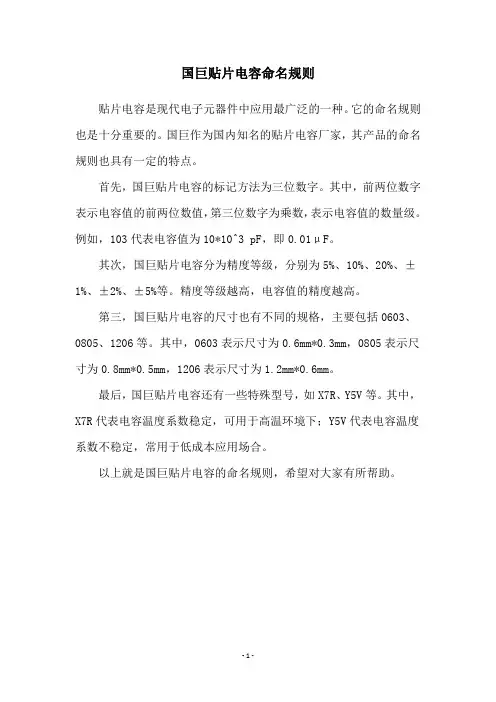
国巨贴片电容命名规则
贴片电容是现代电子元器件中应用最广泛的一种。
它的命名规则也是十分重要的。
国巨作为国内知名的贴片电容厂家,其产品的命名规则也具有一定的特点。
首先,国巨贴片电容的标记方法为三位数字。
其中,前两位数字表示电容值的前两位数值,第三位数字为乘数,表示电容值的数量级。
例如,103代表电容值为10*10^3 pF,即0.01μF。
其次,国巨贴片电容分为精度等级,分别为5%、10%、20%、±1%、±2%、±5%等。
精度等级越高,电容值的精度越高。
第三,国巨贴片电容的尺寸也有不同的规格,主要包括0603、0805、1206等。
其中,0603表示尺寸为0.6mm*0.3mm,0805表示尺寸为0.8mm*0.5mm,1206表示尺寸为1.2mm*0.6mm。
最后,国巨贴片电容还有一些特殊型号,如X7R、Y5V等。
其中,X7R代表电容温度系数稳定,可用于高温环境下;Y5V代表电容温度系数不稳定,常用于低成本应用场合。
以上就是国巨贴片电容的命名规则,希望对大家有所帮助。
- 1 -。

国巨电阻都是以R开头,前面2个字母表示电阻的系列名称。
RC表示一般厚膜电阻,例如:RC0402JR-07100KL;RL表示低阻值电阻,如RL0603JR-070R12L;RT表示高精密厚膜电阻;RJ表示薄膜电阻;RV表示高压电阻。
系列名称(RC/RT/RJ/RV等)后面的4位数表示尺寸,如0100,0201,0402,0603,0805,1206,1210,1218,2010,2512等等。
尺寸后面的字母表示误差。
W=±0.05%,B=±0.1%,C=±0.25%,D=±0.5%,F=±1%,G=±2%,J=±5%,K=±10%,M=±20%误差后面的字母表示封装形式,如R表示纸带,K表示塑料编带。
封装形式后面2位数表示封装尺寸,07表示7寸盘;10表示10寸盘;13表示13寸盘。
封装后面的数值表示阻值,如0R表示0欧;1K=1000欧,1M=1000 000欧。
最后的L表示无铅。
电阻型号、种类和性能一、电阻的型号命名方法:国产电阻器的型号由四部分组成(不适用敏感电阻)第一部分:主称,用字母表示,表示产品的名字。
如R表示电阻,W表示电位器。
第二部分:材料,用字母表示,表示电阻体用什么材料组成,T-碳膜、H-合成碳膜、S-有机实心、N-无机实心、J-金属膜、Y-氮化膜、C-沉积膜、I-玻璃釉膜、X-线绕。
第三部分:分类,一般用数字表示,个别类型用字母表示,表示产品属于什么类型。
1-普通、2-普通、3-超高频、4-高阻、5-高温、6-精密、7-精密、8-高压、9-特殊、G-高功率、T-可调。
第四部分:序号,用数字表示,表示同类产品中不同品种,以区分产品的外型尺寸和性能指标等例如:R T 1 1 型普通碳膜电阻a1}二、电阻器的分类1、线绕电阻器:通用线绕电阻器、精密线绕电阻器、大功率线绕电阻器、高频线绕电阻器。
Approval SheetforThick Film Chip ResistorRL series1% 2% 5%YAGEO CORPORATIONFactory: No.11, Min Chuan Rd., Ta Sheh, Kaohsiung, Taiwan, R.O.C.Tel: 886-7-351-4117 Fax: 886-7-352-6475Headquarters: 3F, No.233-1, Pao Chiao Rd., Hsin Tien, Taipei, Taiwan,R.O.C.Tel: 886-2-2917-7555 Fax: 886-2-2917-4286RL Series Version 2000-3 Page-1RL SeriesVersion 2000-3 Page-21. SUBJECT : This specification describes of RL series chip resistors made of YAGEOCorporation by thick film process.2. PART NUMBER : Part number of the chip resistor is identified by the series, size,tolerance, packing style, temperature coefficient, special type and resistance value.Example :RL 1206 F R - 07 0R02Series Size Resistance Packing Temperature Special ResistanceName Code Tolerance Style Coefficient Type Valueof Resistance(1) Size : (unit: inches)0603=0.063×0.033 1210=0.122×0.102 0805=0.083×0.051 2010=0.197×0.098 1206=0.122×0.0632512=0.250×0.126(2) Tolerance : F=±1%, G=±2%, J=±5%(3) Packaging Style : R =Paper Taping Reel. K =Embossed Plastic Tape Reel. C =Bulk Cassette.(4) T .C .R.: “-“Base on Spec.(5) Special Type : 07= 7 inch Dia. Reel10=10 inch Dia. Reel 13=13 inch Dia. Reel(6) Resistance Value : 10m Ω、20 m Ω、51 m Ω、100 m Ω、330 m Ω、470 m Ω……(7) Resistance Series : E24 (E48/96 on request)RL SeriesVersion 2000-3 Page-33. MARKING :(1) RL0805/RL1206/RL1210/RL2010/RL2512Either tolerance in 5% or 1%: 4 digits, uses MIL Standard resistance marking. “R” signifies decimal place.Value =20m Ω(2) RL0603Tolerance in 5%: 3 digits, uses MIL Standard resistance marking. “R” signifies decimal place.Value =220m Ω1% Tolerance : no marking4. POWER RATING(1) Rated Power at 70°C :RL0603=1/10WRL1210=1/3W RL0805=1/8W RL2012=3/4W RL1206=1/4WRL2512=1W(2) Rated Voltage : The DC or AC (rms) continuous working voltage correspondingto the rated power is determined by the following formula : V= √(P X R)Where V= Continuous rated DC or AC (rms) working voltage (V)P= Rated power (W) R= Resistance value (Ω)5. ELECTRICAL CHARACTERISTICSSTYLE RL0603 RL0805 RL1206 Operating Temp. Range -55°C ~ +125°CDerated to 0 Load at +125°CResistance Range 100mΩ≦Rn<1Ω 20mΩ≦Rn<1Ω 10mΩ≦Rn<1ΩTemperature Coefficient ±600ppm/°C±1500ppm/°CSTYLE RL1210 RL2010 RL2512 Operating Temp. Range -55°C ~ +125°CDerated to 0 Load at +125°CResistance Range 10mΩ≦Rn<1Ω 10mΩ≦Rn<1Ω 10mΩ≦Rn<1ΩTemperature Coefficient ±1500ppm/°CRL Series Version 2000-3 Page-4RL SeriesVersion 2000-3 Page-58. ENVIRONMENTAL CHARACTERISTICS(1) Temperature Coefficient of Resistance (T.C.R.)Test Method : Measure resistance at +25°C or specified room temperature asR 1, then measure at -55°C or +125°C respectively as R 2. Determine the temperature coefficient of resistance from the following formula.R 2-R 1 `T.C.R.= ----------------- X 106(PPM/°C) R 1 (t 2-t 1)Where t 1 =+25°C or specified room temperaturet 2 = -55°C or +125°C test temperatureR 1=resistance at reference temperature in ohms. R 2=resistance at test temperature in ohms.Acceptance Standard : (Refer to item 5)(2) Thermal ShockTest Method : -55±3°C, 2 minutes and +125±2°C, 2 minutes as one cycle. After5 cycles, the specimen shall be stabilized at room temperature for 1 hour minimum and then measure the resistance to determine △R/R(%).Acceptance Standard : ±1.0%(3) Low Temperature OperationTest Method : Place the specimen in a test chamber maintained at -65 °C. After one hour stabilization at this temperature, full rated workingvoltage shall be applied 45 minutes. Have15 minutes after remove the voltage, the specimen shall be removed from the chamber and stabilized at room temperature for 24 hrs. Measure the resistance to determine △R/R(%).Acceptance Standard : ±1.0%No mechanical damage.+5+5 -0 +0+0-5+5+5-0RL SeriesVersion 2000-3 Page-6(4) Short Time OverloadTest Method : Apply 2.5 times of rated voltage but not exceeding the maximumoverload voltage for 5 seconds. Have the specimen stabilized at room temperature for 30 minutes minimum. Measure the resistance to determine △R/R(%).Acceptance Standard : ± 1.0% for 1% tolerance± 2.0% for 2~5% toleranceNo evidence of mechanical damage(5) Insulation ResistanceTest Method : Place the specimen in the jig and apply a rated continuesoverload voltage (R.C.O.V) for one minute as shown. Measure the insulation resistance.Type Voltage Type Voltage RL0603 100V RL1210 400V RL0805 300V RL2010 400V RL1206 400V RL2512 400VAcceptance Standard : ≧10000M Ω(6) Dielectric Withstand VoltageTest Method : Place the specimen in the jig and apply a specified valuecontinuous overload voltage as shown for one minute.Type Voltage TypeVoltage RL0603 100V RL1210 400V RL0805 300V RL2010 400V RL1206 400V RL2512 400VAcceptance Standard : Breakdown voltage>specification and without open/short(7) Resistance to Soldering HeatTest Method: Immerse the specimen in the solder pot at 260±5°C for 10±1seconds. Have the specimen stabilized at room temperature for30 minutes minimum.Measure the resistance to determine △R/R(%).Acceptance Standard:±1.0% & no visible damage(8) Moisture ResistanceTest Method: Place the specimen in the test chamber, and subjected to 42damp heat cycles. Each one of which consists of the steps 1 to 7as figure 1. The total length of test is 1000 hours. After the test,have the specimen stabilized at room temperature for 24 hoursand measure the resistance to determine △R/R(%).Acceptance Standard:±2.0% & no visible damageFig.1 Conditions of change of temperatureRL Series Version 2000-3 Page-7RL SeriesVersion 2000-3 Page-8(9) LifeTest Method : Place the specimen in the oven at 70±2°C. Apply the rated voltageto the specimen at the 1.5 hours on and 0.5 hour off cycle. The total length of test is 1000 hours. After the test, have the specimen stabilized at room temperature for one hour minimum and measure the △R/R(%).Acceptance Standard : ± 2.0% for 1% tolerance± 3.0% for 2~5% tolerance(10) SolderabilityTest Method : Immerse the specimen in the solder pot at 230±5°C for 5 sec.Acceptance Standard : At least 95% solder coverage on the termination.9. TAPING REELUnit :mmStyle Packaging Tape width ∅A ∅B ∅C W TRL0603 RL0805 RL1206 RL1210Paper 8mm 180+0-360+1-0 13.0±0.29.0±0.3 11.4±1RL2010 RL2512Embossed 12mm 180+0-360+1-0 13.0±0.213.0±0.3 15.4±1RL SeriesVersion 2000-3 Page-910. PAPER TAPINGUnit : mmDimensionA B W E F P0 P1 P2 ΦD0 TRL0603 1.10±0.1 1.90±0.1 0.70±0.10RL0805 1.65±0.1 2.40±0.1 0.85±0.10RL1206 1.90±0.1 3.50±0.1 0.85±0.10RL12102.80±0.13.50±0.18.0±0.2 1.75±0.13.5±0.054.0±0.14.0±0.052.0±0.051.5+0.1 -00.85±0.1011. EMBOSSED TAPINGDimensionA B W E F P0P1P2ΦD0ΦD1TRL2010 2.8±0.2 5.4±0.2RL2512 3.5±0.2 6.7±0.212.0±0.3 1.75±0.15.5±0.054.0±0.14.0±0.12.0±0.05 1.5±0.1 1.5±0.25 1.0±0.112. PACKING METHODSPAPERRL Series Version 2000-3 Page-10。