omron串行通信
- 格式:ppt
- 大小:1.54 MB
- 文档页数:37
欧姆龙step和snxt指令-回复欧姆龙(Omron)是一家领先的自动化控制解决方案提供商,致力于为全球范围内的制造业提供高效、可靠和创新的产品。
在欧姆龙产品线中,欧姆龙STEP和SNXT指令是两个重要的编程工具,它们为自动化控制系统的开发提供了强大的支持。
在本文中,我们将深入探讨欧姆龙STEP和SNXT 指令的功能和用法,并逐步解释如何使用它们。
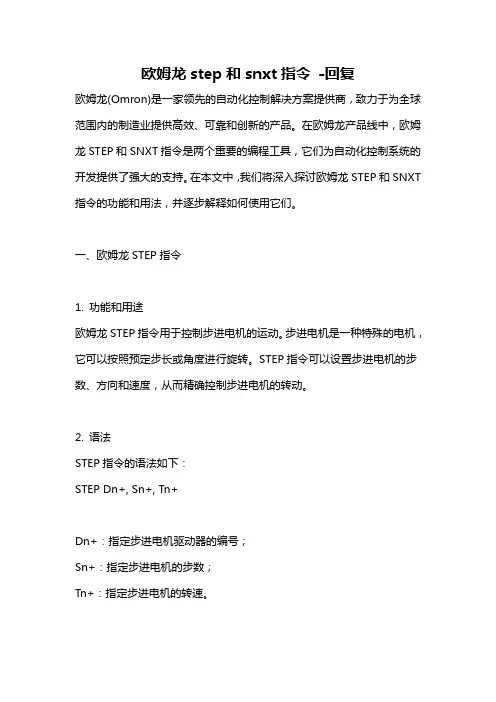
一、欧姆龙STEP指令1. 功能和用途欧姆龙STEP指令用于控制步进电机的运动。
步进电机是一种特殊的电机,它可以按照预定步长或角度进行旋转。
STEP指令可以设置步进电机的步数、方向和速度,从而精确控制步进电机的转动。
2. 语法STEP指令的语法如下:STEP Dn+, Sn+, Tn+Dn+:指定步进电机驱动器的编号;Sn+:指定步进电机的步数;Tn+:指定步进电机的转速。
3. 示例以一个简单的步进电机控制为例,假设我们有一个步进电机,驱动器的编号为D1,需要让步进电机顺时针旋转2000步,并以每分钟1000转的速度旋转。
可以使用以下代码控制:STEP D1+, 2000, 1000二、欧姆龙SNXT指令1. 功能和用途欧姆龙SNXT指令用于与串行通信设备进行通信。
通过SNXT指令,用户可以发送和接收数据,实现与外部设备的数据传输和交互。
这在自动化控制系统中非常有用,可以实现与其他设备的联动控制。
2. 语法SNXT指令的语法如下:SNXT "Function Code", Dn+, Sn+, Address, Length"Function Code":指定SNXT指令的功能码;Dn+:指定串行通信设备的编号;Sn+:指定发送或接收的数据区域编号;Address:指定读取或写入数据的起始地址;Length:指定要读取或写入的数据长度。
3. 示例以与PLC进行数据交互为例,假设我们要从PLC的地址D100读取10个数据,并将其存储到数据区域S1。

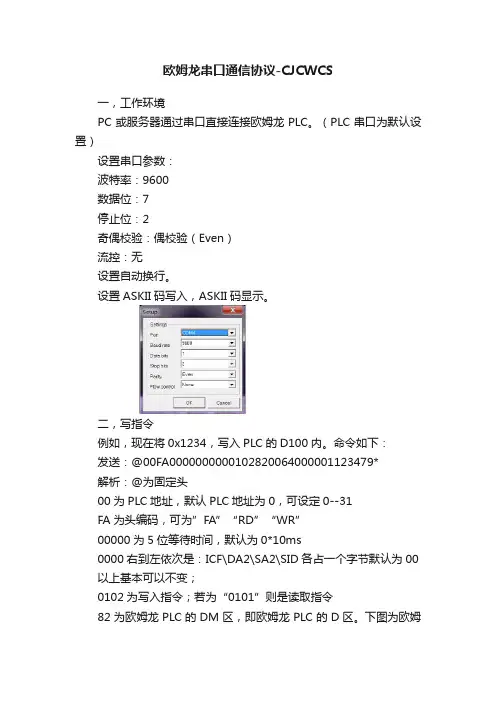
欧姆龙串口通信协议-CJCWCS一,工作环境PC或服务器通过串口直接连接欧姆龙PLC。
(PLC串口为默认设置)设置串口参数:波特率:9600数据位:7停止位:2奇偶校验:偶校验(Even)流控:无设置自动换行。
设置ASKII码写入,ASKII码显示。
二,写指令例如,现在将0x1234,写入PLC的D100内。
命令如下:发送:@00FA0000000000102820064000001123479*解析:@为固定头00为PLC地址,默认PLC地址为0,可设定0--31FA为头编码,可为”FA”“RD”“WR”00000为5位等待时间,默认为0*10ms0000右到左依次是:ICF\DA2\SA2\SID各占一个字节默认为00 以上基本可以不变;0102为写入指令;若为“0101”则是读取指令82为欧姆龙PLC的DM区,即欧姆龙PLC的D区。
下图为欧姆龙PLC对应区域的标识。
0064为16进制的100,即D10000为位地址,即D100.000001为要写入的字数1234为要写入的内容,十六进制的123479为XOR校验值。
(这个我们最后讨论)*为结束标志。
(后面还有一位回车符\CR)返回:@00FA00400000000102000040*解析:其他都差不多意思,只有红色的0000表示写入成功。
三,读取命令例如,现在将D50字的内容读出来。
命令如下:发送:@00FA000000000010182002800000176*解析:蓝色部分不做解析了。
0101为读指令82为DM区002800为D50.000001为1个字76为XOR校验值。
返回:@00FA004000000001010000A5A543*解析:其他都差不多意思,黄色的0000表示读取成功;红色A5A5是从D50读取出来的值。
四,XOR校验位。
欧姆龙的串口校验方式为逐位异或校验。
就以读取指令来说明吧:@00FA000000000010182002800000176*首先将@00FA0000000000101820028000001的ASKII码逐一转为HEX。
串行通信第一节上位机链接通信概要上位机链接系统即Hostlink系统是对于FA系统一种即优化又经济的通信方式,它适合一台上位机与一台或多台PLC进行链接。
上位机可对PLC传送程序,并监控PLC的数据区,以及控制PLC的工作情况。
HOSTLINK系统允许一台上位机通过上位机链接命令向HOSTLINK系统的PLC发送命令,PLC处理来自上位机的每条指令,并把结果传回上位机。
一.HOSTLINK 系统特点通信即可采用RS-232C方式,又可采用RS-422方式,RS-232C方式是基于1:1的通信,距离为15m。
RS-422方式是实现1:N的通信,即一台上位机与多台PLC进行通信,最多可有32台PLC连接到上位机,通信距离最大可达500m。
上位机监控上位机可对PLC的程序进行传送或读取,并可对PLC数据区进行读写操作。
双重检查系统所有通信都将作奇偶检验和帧检验,从而能估计出通信中的错误。
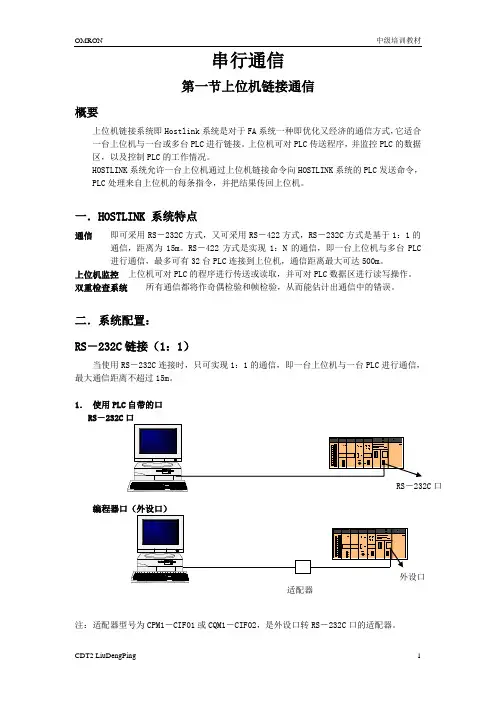
二.系统配置:RS-232C链接(1:1)当使用RS-232C连接时,只可实现1:1的通信,即一台上位机与一台PLC进行通信,最大通信距离不超过15m。
1.使用PLC自带的口RS-232C口编程器口(外设口)注:适配器型号为CPM1-CIF01或CQM1-CIF02,是外设口转RS-232C口的适配器。
2.使用上位链接单元:注:上位链接单元的型号为C200H-LK201,它提供的是一个25芯的RS-232C口。
若连的是CS1系列的PLC,可用通信模块CS1W-SCU21。
1.使用通信板:RS-422链接(1:N)注:CPM1-CIF11为外设口转RS-422口的适配器NT-AL001为RS-232C与RS-422转换的适配器B500-AL001为分支器,其功能是将一路RS-422信号转成两路RS-422信号上位机链接模块为C200H-LK202,是带RS-422端口的模块。
三.上位机链接参数设置通信方式设置通信方式为上位机链接通信(这是缺省设置)。
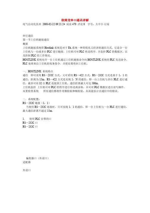
欧姆龙串口通讯详解电气自动化技术2008-02-22 09:21:24 阅读470 评论0 字号:大中小订阅串行通信第一节上位机链接通信概要上位机链接系统即Hostlink系统是对于FA系统一种即优化又经济的通信方式,它适合一台上位机与一台或多台PLC进行链接。
上位机可对PLC传送程序,并监控PLC的数据区,以及控制PLC的工作情况。
HOSTLINK系统允许一台上位机通过上位机链接命令向HOSTLINK系统的PLC发送命令,PLC处理来自上位机的每条指令,并把结果传回上位机。
一.HOSTLINK 系统特点通信即可采用RS-232C方式,又可采用RS-422方式,RS-232C方式是基于1:1的通信,距离为15m。
RS-422方式是实现1:N的通信,即一台上位机与多台PLC进行通信,最多可有32台PLC连接到上位机,通信距离最大可达500m。
上位机监控上位机可对PLC的程序进行传送或读取,并可对PLC数据区进行读写操作。
双重检查系统所有通信都将作奇偶检验和帧检验,从而能估计出通信中的错误。
二.系统配置:RS-232C链接(1:1)当使用RS-232C连接时,只可实现1:1的通信,即一台上位机与一台PLC进行通信,最大通信距离不超过15m。
1.使用PLC自带的口RS-232C口RS-232C口编程器口(外设口)适配器外设口注:适配器型号为CPM1-CIF01或CQM1-CIF02,是外设口转RS-232C口的适配器。
2.使用上位链接单元:上位链接单元注:上位链接单元的型号为C200H-LK201,它提供的是一个25芯的RS-232C口。
若连的是CS1系列的PLC,可用通信模块CS1W-SCU21。
1.使用通信板:通信板RS-422链接(1:N)NT-AL001CPM1-CIF11NT-AL001B500-AL001RS-232C口外设口多至32台上位链接模块注:CPM1-CIF11为外设口转RS-422口的适配器NT-AL001为RS-232C与RS-422转换的适配器B500-AL001为分支器,其功能是将一路RS-422信号转成两路RS-422信号上位机链接模块为C200H-LK202,是带RS-422端口的模块。


omron串行通信xx年xx月xx日CATALOGUE目录•omron串行通信协议简介•omron串行通信协议的硬件要求•omron串行通信协议的软件要求•omron串行通信协议的调试与检测•omron串行通信协议的应用案例•omron串行通信协议的发展趋势及未来展望01 omron串行通信协议简介OMRON串行通信协议是一种用于设备间进行数据传输的通信协议,它定义了数据传输格式、波特率、字符长度等参数。
它采用主从模式,由一个主设备控制数据的传输,从设备响应主设备的请求,实现设备间的数据交换。
OMRON串行通信协议适用于多个设备间的数据传输,特别是远距离的数据传输。
它可用于各种工业自动化应用场景,如PLC、传感器、机器人等设备的通信。
1 2 3OMRON串行通信协议具有高效、稳定、安全的特点。
它支持多种串行接口,如RS-232、RS-485、CAN等,扩展性强。
OMRON串行通信协议简单易用,开发周期短,可降低开发成本。
02omron串行通信协议的硬件要求计算机处理器Omron串行通信协议需要使用计算机的处理器进行数据传输和控制。
计算机内存为了能够处理大量的数据,计算机需要有足够的内存空间。
计算机的硬件要求Omron串行通信协议需要使用RS-232接口进行数据传输。
RS-232接口如果需要长距离通信,可以使用RS-485接口进行数据传输。
RS-485接口通信接口的硬件要求03停止位和流控制Omron串行通信协议支持停止位和流控制,以确保数据传输的稳定性和可靠性。
串行通信接口的硬件要求01数据传输速率Omron串行通信协议支持不同的数据传输速率,如9600bps、19200bps、38400bps等。
02数据位和校验位Omron串行通信协议支持不同的数据位和校验位,以满足不同应用场景的需求。
03omron串行通信协议的软件要求计算机操作系统的软件要求Windows操作系统对于Windows操作系统,需要安装OMRON PLC的驱动程序,如CP1H、CJ1M等,以及串行通信支持库。
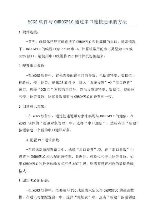
MCGS软件与OMRONPLC通过串口连接通讯的方法1.硬件连接:-首先,确保你已经正确连接了OMRONPLC和计算机的串口。
通常情况下,OMRONPLC的编程口为RS232串口,计算机常用的串口类型为DB9或DB25接口。
请使用串口线缆将PLC和计算机连接起来。
2.配置串口参数:-在MCGS软件中,首先需要配置串口的参数,包括波特率、数据位、校验位、停止位等。
在MCGS软件中,进入“系统设置”->“串口设置”窗口,选择“COM口”对应的串口号,然后设置波特率、数据位、校验位和停止位等参数,这些参数需要与OMRONPLC的设置相一致。
3.创建通讯对象:-在MCGS软件中,通过创建通讯对象来实现与OMRONPLC的通信。
在MCGS软件的“通讯对象管理”中,选择“串口通信”,然后点击“新建”按钮创建一个新的串口通讯对象。
4.配置PLC通信参数:-在通讯对象配置窗口中,选择“串口设置”项,在“串口参数”中设置与OMRONPLC相匹配的波特率、数据位、校验位和停止位等参数。
如果OMRONPLC的数据传输方式不是ASCII码,则需要设置相应的数据传输格式。
5.编写PLC地址表:-在MCGS软件中,需要编写PLC地址表来定义与OMRONPLC的通讯数据。
在通讯对象配置窗口中,选择“地址表”项,点击“新建”按钮创建一个新的地址表。
然后,根据需要在地址表中添加地址,通常包括输入寄存器、输出寄存器、数据寄存器等。
这些地址与OMRONPLC的内存区域相对应。
6.配置读写命令:-在通讯对象配置窗口中,选择“读写配置”项,点击“新建”按钮创建一个新的读写命令。
在读写命令配置窗口中,配置读写的地址、数据长度、读写方式等参数。
根据需要,可以配置多个读写命令来满足不同的通讯需求。
7.启动通讯:-配置完通讯对象、地址表和读写命令后,可以点击通讯对象管理窗口中的“启动”按钮来启动通讯。
如果通讯配置正确,MCGS软件将能够与OMRONPLC建立连接,并可以实现数据的读取和写入。


3_5_3Sending Commands from the Computer to the CPU Unit Command Format from Host ComputerUse the following command format to send FINS commandsfrom the host computer to the CPU Unit.Note The length of the command must be not more than 1,114characters. FINS commands cannot be partitioned intoseparate frames for sending.Sending Commands to a CPU Unit Directly Connected to the Host ComputerNote The following format is also applicable for a host computerconnected to a Serial Communications Board or a Serial Communications Unit.Unit No.Header codeResponsewait time FINS command code Text(1,080 characters = 540 bytes max.)TerminatorICFDA2SA2SID FCS x*x x x x x x x x x x Sending Commands to a CPU Unit on a NetworkNote The following format can also be used to send FINScommands to a CPU Unit connected to the host computer.Host Link Settings @The @ symbol must be attached to the beginning of the command.Unit No.Headercode Responsewait time FINS command code Text (1,080 characters = 540 bytes max.)TerminatorICF RSV GCT DNA DA1DA2SNASA1SA2SID FCS x xx x x x x xx x x x x x x x x*Unit NumberThe unit number set is that of the destination CPU Unit connected to the host computer. When the host computer is connected to a CPU Unit, the unit number is designated in the PC Setup.When the host computer is connected to a Serial Communications Board or a Serial Communications Unit, the unit number is the designated in the Setup for the Board or Unit.Header CodeThe header code distinguishes between different types of commands. Set “FA” (ASCII: 46, 41) when using FINS commands.Response Wait TimeThe response wait time sets the time from when the CPU Unit receives a command block until it starts to return a response. It can be set from 0 to F in hexadecimal, in units of 10 ms. Example:If F(15) is set, the response will begin to be returned 150 ms (15% 10 ms) after the command block was received. ICF (Information Control Field)Specifies whether or not there are network relays. Set “80”(ASCII: 38,30) when sending an FINS command to a CPU Unit on a network. Set “00” (ASCII: 30,30) when sending to a CPU Unit connected directly to the host computer.RSV (Reserved)Set “00” (ASCII: 30,30). Setting RSV is required only when sending to a CPU Unit on a network.GCT (Gateway Count)This is the number of networks through which the transmission can be relayed. Set”02” (ASCII: 30,32). Setting GCT is required only when sending to a CPU Unit on a network.DNA, DA1, DA2Set the destination network, node, and unit addresses.DNA (Destination Network Address)Set between 00 and 7F hex (0 and 127 decimal). Setting DNA is required only when sending to a CPU Unit on a network.DA1 (Destination Node Address)Set within the following ranges. Setting DA1 is required only when sending to a CPU Unit on a network.Ethernet Unit:01 to 7E hex (1 to 126 decimal)Controller Link Unit:01 to 20 hex (1 to 32 decimal)SYSMAC NET:01 to 7E hex (1 to 126 decimal)SYSMAC LINK:01 to 3E hex (1 to 62 decimal)DA2 (Destination Unit Address)Refer to 3_4_2 Addresses in FINS Commands for detailson unit addresses.In Host Link mode, it is assumed that the destination unitis the CPU Unit, so set “00: (ASCII: 30, 30).SNA (Source Network Address), SA1 (Source NodeAddress)Set the source network and node addresses. Set both to “00”(ASCII: 30, 30) regardless of whether or not there is anetwork relay.Setting SNA and SN1 is required only when sending to aCPU Unit on a network.SA2 (Source Unit Address)Set the unit address of the Unit physically connected to thehost computer. The setting changes depending on theconnected Unit.When connected to the CPU Unit, Serial CommunicationsBoard, or a Serial Communications Unit, set “00” to indicatethe CPU Unit (ASCII: 30, 30). By setting “00”, the internalprocess will change the unit address to the unit address forthe appropriate serial port. Refer to 3_4_2 Addresses in FINSCommands and for details on unit addresses.SID (Source ID)The SID is used as a counter when resending. It shouldnormally be set to “00” (ASCII: 30, 30).Command Code, TextSet the command code and text according to the FINScommand and response formats.FCS (Frame Check Sequence)Set a 2-character FCS. Refer to FCS Calculations under 2_2Command/Response Formats for the FCS calculationmethod.TerminatorThe terminator is a required delimiter at the end of acommand. Set the terminator to *CR (ASCII: 2A, 0D).Response Format from a CPU UnitThe following response format is used to return responsesfrom the CPU Unit to the host computer.Note The length of the response must be not more than 1,115characters. Of this, the response data without the responsecode is 1,076 characters (538 bytes).Responses from a CPU Unit Directly Connected to the Host ComputerUnit No.Headercode FINS command code Data(1,076 characters= 538 bytes)Terminator FINS response codeICF DA2SA2SID FCS x xx xx x x x x x x xx x *Responses from a CPU Unit on a NetworkHost Link Settings @The @ symbol must be attached to the beginning of theresponse.Unit Number and Header CodeThe same unit number and header code specified in the FINScommand that was received will be returned.ICF (Information Control Field)For a CPU Unit on a network, “C0” (ASCII: 43, 30) will bereturned. For a CPU Unit connected directly to the host computer, “40” (ASCII: 34,30) will be returned.Unit No.Headercode FINS command code Data(1,076 characters =538 bytes))TerminatorFINS response codeICF RSV GCT DNA DA1DA2SNA SA1SA2SID FCS xx xx x x x x x x x x x x x x x x xx *RSV (Reserved)This section is reserved for the system. Set “00” (ASCII:30,30).GCT (Gateway Count)The same GCT that was specified in the command that wasreceived will be returned. Setting GCT is required in theresponse format only from a CPU Unit on a network.DNA (Destination Network Address), DA1 (DestinationNode Address), DA2 (Destination Unit Address)The same contents specified for SNA, SA1, and SA2 in thecommand that was received will be returned.Setting DNA and DA1 is required for response formats onlyfrom a CPU Unit on a network.SNA (Source Network Address), SA1 (Source NodeAddress), SA2 (Source Unit Address)The same contents specified for DNA, DA1, and DA2 in thecommand that was received will be returned.Setting SNA and SN1 is required for response formats onlyfrom a CPU Unit on a network.SID (Source ID)The SID that was specified in the command that was receivedwill be returned.Command Code, Response Code, TextThe command code, response code, and text correspondingto the FINS command and response formats will be returned.FCS (Frame Check Sequence)A 2-character FCS will be returned. Refer to FCSCalculations under 2_2 Command/Response Formats for theFCS calculation method.TerminatorThe terminator is a required delimiter at the end of acommand. The terminator *CR (ASCII: 2A, 0D) will bereturned.Example: FINS Command Settings for Sending to CPU Unit on a NetworkWith Host Link communications, FINS commandtransmissions and receptions are handled in ASCII, sohexadecimal values in FINS command frames must be sentas ASCII. For example, the hexadecimal value “0” would be“30 hex” in ASCII, and the hexadecimal value “A” would be“41 hex” in ASCII.The destination network address, node address, and unitnumber address are explained using the following network asan example.Host computer Host Link Controller Link, network address 5Ethernet Unit Node 10Ethernet network, network address 10Controller Link Unit Node 3Ethernet Unit Node 12PC (B)PC (A)Sending a Command from a Host Computer to PC (A)The following addresses are specified to the CPU Unit at network address 5, node address 3:Destination network address (DNA):05 (30, 35)Destination node address (DA1): 03 (30, 33)Destination unit address (DA2): 00 (30, 30)(Command addressed to CPU Unit)Sending a Command from a Host Computer to PC (B)The following addresses are specified to the CPU Unit at network address 10, node address 12:Destination network address (DNA):0A (30, 41)Destination node address (DA1): 0C (30, 43)Destination unit address (DA2): 00 (30, 30)(Command addressed to CPU Unit)Back Back to the Table of Contents Next。
串行通信串行通信即通过使用PLC上的串行口(RS-232C口或RS-422/485口)同第三方设备进行通信的过程。
对于PLC上的串行口,它所支持的通信方式有很多种,有连接上位机的上位机通信方式,有连接PLC的1:1PC链接方式,还有连接第三方的通信方式等等。
下面进行一一介绍。
第一节上位机链接通信概要上位机链接系统即Hostlink系统是对于FA系统一种即优化又经济的通信方式,它适合一台上位机与一台或多台PLC进行链接。
上位机可对PLC传送程序,并监控PLC的数据区,以及控制PLC的工作情况。
HOSTLINK系统允许一台上位机通过上位机链接命令向HOSTLINK系统的PLC发送命令,PLC处理来自上位机的每条指令,并把结果传回上位机。
一.HOSTLINK 系统特点通信即可采用RS-232C方式,又可采用RS-422方式,RS-232C方式是基于1:1的通信。
RS-422方式是实现1:N的通信,即一台上位机与多台PLC进行通信,最多可有32台PLC连接到上位机。
也可采用光缆进行连接,但光缆的话必须使用专用上位机监控上位机可对PLC的程序进行传送或读取,并可对PLC数据区进行读写操作。
双重检查系统所有通信都将作奇偶检验和帧检验,从而能估计出通信中的错误。
二.系统配置:RS-232C链接(1:1)当使用RS-232C链接时,只可实现1:1的通信,即一台上位机与一台PLC进行通信,最大通信距离不超过15m。
1.使用PLC自带的口RS-232C口编程器口(外设口)注:适配器型号为CPM1-CIF01或CQM1-CIF02,是外设口转RS-232C口的适配器。
2.使用上位链接单元:注:上位链接单元的型号为C200H-LK201,它提供的是一个25芯的RS-232C口。
若连的是CS1系列的PLC,还可通过通信模块CS1W-SCU21。
3.使用通信板:注:通信板型号为C200HW-COM02/04/05/06,均带RS-232C口。