Safety relay
- 格式:ppt
- 大小:3.37 MB
- 文档页数:33
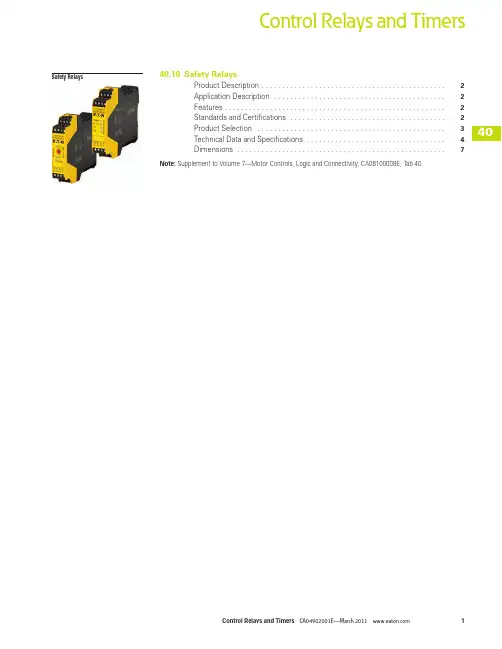
1Control Relays and TimersSafety Relays40.10Safety RelaysProduct Description . . . . . . . . . . . . . . . . . . . . . . . . . . . . . . . . . . . . . . . . . . . . .2Application Description . . . . . . . . . . . . . . . . . . . . . . . . . . . . . . . . . . . . . . . . . .2Features . . . . . . . . . . . . . . . . . . . . . . . . . . . . . . . . . . . . . . . . . . . . . . . . . . . . . .2Standards and Certifications . . . . . . . . . . . . . . . . . . . . . . . . . . . . . . . . . . . . . .2Product Selection . . . . . . . . . . . . . . . . . . . . . . . . . . . . . . . . . . . . . . . . . . . . . .3Technical Data and Specifications . . . . . . . . . . . . . . . . . . . . . . . . . . . . . . . . . .4Dimensions . . . . . . . . . . . . . . . . . . . . . . . . . . . . . . . . . . . . . . . . . . . . . . . . . . .7Note: Supplement to Volume 7—Motor Controls, Logic and Connectivity, CA08100008E, Tab 40.40.10Control Relays and T imersSafety RelaysSafety RelaysContentsDescription PageSafety RelaysProduct Selection . . . . . . . . . . . . . . . . . . . . . . . . . . . . . . 3Technical Data and Specifications . . . . . . . . . . . . . . . . . 4Dimensions . . . . . . . . . . . . . . . . . . . . . . . . . . . . . . . . . . 7Product DescriptionSafety relays are intended toreliably monitor the signalsfrom safety devices at alltimes and switch off quicklyand reliably in an emergency.Single-channel and dualchannel versions are availablefor the construction of safetyapplications. The internallogic of the safety relaysmonitors the safety circuits(emergency stop, guard door,and so on) and activates theenable paths in a fault-freecondition. Upon actuation ofthe safety device or in theeven of a fault, the enablepaths are switched off. Anyfaults that occur in the controlcircuit, such as ground fault,cross connection fault or wirebreakage are also detected.Application DescriptionEaton’s ESR5 safety relaysprovide optimal safety and ahigh degree of reliability onplant machinery. Applicationsthat meet the highestsafety requirements inaccordance with EN 954-1,EN ISO 13849-1 up to PL eand accordance withIEC 62061 up to SILCL 3can be realized with theESR5 safety relay.Compatible with a widevariety of safety devices:●Emergency stops●Rope pulls●Two-hand control stations●Light curtain (OSSD)●Gate enable device●Safety switchesFeatures●Use for the highestsafety requirements inaccordance with EN 954-1EN ISO 13849-1,IEC 62061 and EC 61508●Suitable for the worldmarket with UL, cULcertifications and TÜVRhineland functionalsafety certifications●Applicable for EN 60204stop categories 0 or 1●Plug-in screw terminalsfor fast and fault-freereplacement●Multi-voltage versions(24–230 Vac/Vdc) for aflexible range of application●Delayed and non-delayedcontact expansionsaccommodate a widevariety of applicationsStandards andCertifications●UL 508; CSA-C22.2 No14-95; CE Marked●UL/cUL file number:E29184●Degree of protection: IP20●TÜV Rhineland certified●UL/cULus listed2340.10Control Relays and TimersSafety RelaysProduct SelectionTechnical OverviewApplication OverviewApplication Overview, continuedNotesᕃLaser scanners or light curtains with OSSD outputs. ᕄ All main units can also be reset automatically or manually.Single ChannelDual ChannelSafety Output (NO)SafetyOutput (NO) (Delayed)Output Delay SignalOutput (NC)Feedback Output Control Voltage RemovableTerminal Blocks Type of UnitCatalog Number ■ —4——1—24 Vac/Vdc ■ Main ESR5-NO-41-24VAC-DC ■ ■ 2——1—24 Vac/Vdc ■ Main ESR5-NO-21-24VAC-DC ■ ■ 3——1—24 Vac/Vdc ■ Main ESR5-NO-31-24VAC-DC ■ ■ 3——1—230 Vac ■ Main ESR5-NO-31-230VAC ■ ■ 3——1—24–230 Vac/Vdc ■ Main ESR5-NO-31-AC-DC ■■ 220.1–30s——24 Vdc ■ Main ESR5-NV3-30—■ 2——1—24 Vac/Vdc ■ Main ESR5-NZ-21-24VAC-DC ■ —5——1124 Vac/Vdc ■ Expansion ESR5-NE-51-24VAC-DC ■ ——40.3–3s 1124 Vdc■ ExpansionESR5-VE3-42Emergency Stop SafetySwitchesLight Curtain/OSSD ᕃTwo-Hand Control(EN 574 Type III C)ContactExpansion Off-Delayed Cross Circuit Recognition MonitoredManual Reset ᕄCatalog Number ■ ■——————ESR5-NO-41-24VAC-DC ■ ■ ————■ —ESR5-NO-21-24VAC-DC ■ ■————■ —ESR5-NO-31-24VAC-DC ■ ■ ————■ ■ ESR5-NO-31-230VAC ■ ■————■ ■ ESR5-NO-31-AC-DC ■■ ■——■■ ■ESR5-NV3-30—■—■——■—ESR5-NZ-21-24VAC-DC ————■———ESR5-NE-51-24VAC-DC ————■■——ESR5-VE3-42SingleChannelDual Channel Stop Category EN 60204Control Category to EN 954-1Achievable PL per ISO 13849-1Achievable SIL per EN IEC 62061Catalog Number ■ —02PL d SIL 3ESR5-NO-41-24VAC-DC ■ ■ 04PL e SIL 3ESR5-NO-21-24VAC-DC ■ ■ 04PL e SIL 3ESR5-NO-31-24VAC-DC ■ ■ 04PL e SIL 3ESR5-NO-31-230VAC ■ ■ 04PL e SIL 3ESR5-NO-31-AC-DC ■■ 0/14PL e SIL 3ESR5-NV3-30—■04PL e SIL 3ESR5-NZ-21-24VAC-DC ■ —04PL e SIL 3ESR5-NE-51-24VAC-DC ■—13PL dSIL 2ESR5-VE3-42Safety Relays40.10Control Relays and TimersSafety RelaysTechnical Data and SpecificationsSafety RelayDescription Unit ESR5-NO-21_ESR5-NO-41_ESR5-NO-31-24VAC-DC ESR5-NZ-21_GeneralStandards EN ISO 13849-1, IEC 62061,IEC 61508, DIN EN 50178,UL/CUL listedEN ISO 13849-1, IEC 62061,IEC 61508, DIN EN 50178,UL/CUL listedEN ISO 13849-1, IEC 62061,IEC 61508, DIN EN 50178,UL/CUL listedEN ISO 13849-1, IEC 62061,IEC 61508, DIN EN 50178,UL/CUL listedType-dependent standards———EN 574 Part no. IIIC Lifespan, mechanical—c (contacts)x 10610101010Maximum operating frequency Ops/h3600360036003600Climatic proofing Cold according toEN 60068-2-1, dry heataccording to EN60068-2-2,damp heat according toEN 60068-2-3Dry heat according toEN60068-2-2, damp heataccording to EN 60068-2-3Cold according toEN 60068-2-1, dry heataccording to EN60068-2-2,damp heat according toEN 60068-2-3Dry heat according toEN60068-2-2, damp heataccording to EN 60068-2-3Ambient temperature°F (°C)–4° to 131° (–20° to 55°)–4° to 131° (–20° to 55°)–4° to 131° (–20° to 55°)–4° to 131° (–20° to 55°) Ambient temperature storage°F (°C)–13° to 167° (–25° to 75°)–13° to 167° (–25° to 75°)–13° to 167° (–25° to 75°)–13° to 167° (–25° to 75°) Mounting position Any Any Any AnyVibration resistance (IEC/EN 60068-2-6)2g, frequency: 10–150 Hz,amplitude: 0.15 mm2g, frequency: 10–150 Hz,amplitude: 0.15 mm2g, frequency: 10–150 Hz,amplitude: 0.15 mm2 g, frequency: 10–150 Hz,amplitude: 0.15 mm Shock resistance (IEC 60068-2-27)————Protection typeHousing IP20IP20IP20IP20Terminals IP20IP20IP20IP20Protection against direct contact whenactuated from front (IEC 0106 Part 100)Finger- and back-of-handproofFinger- and back-of-handproofFinger- and back-of-handproofFinger- and back-of-handproofWeight kg0.170.220.170.22Terminal capacitySolid or flexible mm2 1 x (0.2–2.5)2 x (0.2–1)1 x (0.2–2.5)2 x (0.2–1)1 x (0.2–2.5)2 x (0.2–1)1 x (0.2–2.5)2 x (0.2–1)Flexible with ferrule mm2 1 x (0.25–2.5)2 x (0.25–1)1 x (0.25–2.5)2 x (0.25–1)1 x (0.25–2.5)2 x (0.25–1)1 x (0.25–2.5)2 x (0.25–1)Solid or stranded AWG24–1224–1224–1224–12Terminal screwPozidriv screwdriver Size2222Flat-blade screwdriver mm0.6 x 3.50.6 x 3.50.6 x 3.50.6 x 3.5Max. tightening torque Nm0.60.60.60.6Main ContactsRated impulse withstand voltage—U imp Vac6000400040006000Overvoltage category/pollution degreeOutside III/2III/2III/2III/2Inside————Rated insulation voltage—U i Vac250250250250Rated operating voltage—U e Vac230230230230Rated operation currentAC-15230V (360 ops./h)—I e A5454230V (3600 ops./h)—I e A3333DC-1324V (360 ops./h)—I e A646424V (3600 ops./h)—I e A3 2.53 2.5Max. summation current of all poles24 Vac/Vdc devices A72727272230 Vac devices A————Square of the total current(and total current)of all current paths72 A2 (6 + 6)72 A2 (4.2 + 4.2 + 4.2 + 4.2)72 A2 (4.9 + 4.9 + 4.9)72 A2 (6 + 6)Short-circuit protectionMax. fuse A gG/gL1061064540.10Control Relays and TimersSafety RelaysSafety Relay, continuedDescriptionUnitESR5-NO-21_ESR5-NO-41_ESR5-NO-31-24VAC-DCESR5-NZ-21_Power Supply Circuit Actuating voltage 50/60 Hz Vac 24242424Actuating voltage—U sVdc 24242424Voltage tolerance pick-up voltage x e 0.85–1.10.85–1.10.85–1.10.85–1.1Power consumption AC operated 50/60 Hz VA ————AC operated 50/60 Hz W 3.4 3.4 3.43DC operatedW1.61.61.61.5Fuse for control circuit supply 24V Short-circuit proof Short-circuit proof Short-circuit proof Short-circuit proof 115/230V ————Control Circuit Rated output voltage Vdc 24242424Rated operational current mAS12, S22: 30, S34: 45S12: 65, S34: 40S12, S22: 30, S34: 45S11, S21: 60, Y2: 45Resistance—R 50225022Short-circuit current A 2.3 2.3 2.3 2.3Response time ms 1006510050Recovery timems ————Response time with reset monitoring—t A1ms ————Response time without reset monitoring—t A2ms 1006510050Reset time—t R /t R1ms Single-channel 45;dual-channel 1045Single-channel 45;dual-channel 1020Minimum on duration—t M ms ————Recovery time—t Wms Approx. 1000Approx. 1000Approx. 1000Approx. 1000Synchronous monitoring time—t Sms ———500Electromagnetic Compatibility (EMC)Emitted interference EN 61000-6-4EN 61000-6-4EN 61000-6-4EN 61000-6-4Interference immunityAccording to EN 61000-6-2,EN 62061According to EN 61000-6-2According to EN 61000-6-2,EN 62061According to EN 61000-6-240.10Control Relays and TimersSafety RelaysSafety Relay, continuedDescription Unit ESR5-NO-31-230VACESR5-NO-31-24V-230VAC-DC ESR5-NV3_ESR5-VE3_ESR5-NE-51_GeneralStandards EN ISO 13849-1, IEC 62061,IEC 61508, DIN EN 50178,UL/CUL listedEN ISO 13849-1, IEC 62061,IEC 61508, DIN EN 50178,UL/CUL listedEN ISO 13849-1, IEC 62061,IEC 61508, DIN EN 50178,UL/CUL listedEN ISO 13849-1, IEC 62061,IEC 61508, DIN EN 50178,UL/CUL listedEN ISO 13849-1, IEC 62061,IEC 61508, DIN EN 50178,UL/CUL listedType-dependent standards EN 60204(if applicable)EN 60204(if applicable)EN 60204(if applicable)——Lifespan, mechanical—c (contacts)x 1061010101010Maximum operating frequency Ops/h3600360036009003600Climatic proofing Dry heat according toEN60068-2-2, damp heataccording to EN 60068-2-3Dry heat according toEN60068-2-2, damp heataccording to EN 60068-2-3Cold in accordance with:EN 60068-2-1, dry heat inaccordance with EN60068-2-2, humiditystorage test in accordancewith 60068-2-78Dry heat according toEN60068-2-2, damp heataccording to EN 60068-2-3Dry heat according toEN60068-2-2, damp heataccording to EN 60068-2-3Ambient temperature°F (°C)–4° to 131° (–20° to 55°)–4° to 131° (–20° to 55°)–4° to 113° (–20° to 45°)–4° to 131° (–20° to 55°)–4° to 131° (–20° to 55°) Ambient temperature storage°F (°C)–13° to 167° (–25° to 75°)–13° to 167° (–25° to 75°)–13° to 167° (–25° to 75°)–13° to 167° (–25° to 75°)–13° to 167° (–25° to 75°) Mounting position Any Any Any Any AnyVibration resistance (IEC/EN 60068-2-6)2g, frequency: 10–150 Hz,amplitude: 0.15 mm2g, frequency: 10–150 Hz,amplitude: 0.15 mm2g, frequency: 10–150 Hz,amplitude: 0.15 mm2g, frequency: 10–150 Hz,amplitude: 0.15 mm2g, frequency: 10–150 Hz,amplitude: 0.15 mm Shock resistance (IEC 60068-2-27)—————Protection typeHousing IP40IP40IP20IP20IP20Terminals IP20IP20IP20IP20IP20Protection against direct contact whenactuated from front (IEC 0106 Part 100)Finger- and back-of-handproofFinger- and back-of-handproofFinger- and back-of-handproofFinger- and back-of-handproofFinger- and back-of-handproofWeight kg0.30.30.170.170.22Terminal capacitySolid or flexible mm2 1 x (0.2–2.5)2 x (0.2–1)1 x (0.2–2.5)2 x (0.2–1)1 x (0.2–2.5)2 x (0.2–1)1 x (0.2–2.5)2 x (0.2–1)1 x (0.2–2.5)2 x (0.2–1)Flexible with ferrule mm2 1 x (0.25–2.5)2 x (0.25–1)1 x (0.25–2.5)2 x (0.25–1)1 x (0.25–2.5)2 x (0.25–1)1 x (0.25–2.5)2 x (0.25–1)1 x (0.25–2.5)2 x (0.25–1)Solid or stranded AWG24–1224–1224–1224–1224–12Terminal screwPozidriv screwdriver Size22222Flat-blade screwdriver mm0.6 x 3.50.6 x 3.50.6 x 3.50.6 x 3.50.6 x 3.5Max. tightening torque Nm0.60.60.60.60.6Main ContactsRated impulse withstand voltage—U imp Vac60006000400040004000Overvoltage category/pollution degreeOutside III/2III/2III/2III/2III/2 Inside—————Rated insulation voltage—U i Vac250250250250250Rated operating voltage—U e Vac230230*********Rated operation currentAC-15230V (360 ops./h)—I e A44—54230V (3600 ops./h)—I e A33333DC-1324V (360 ops./h)—I e A44—6424V (3600 ops./h)—I e A 2.5 2.533 2.5Max. summation current of all poles24 Vac/Vdc devices A5050495050230 Vac devices A5050———Square of the total current(and total current)of all current paths50 A2 (4 + 4 + 4)50 A2 (4 + 4 + 4)50 A2 (4 + 4 + 4)49 A2(3.5 + 3.5 + 3.5 + 3.5)50 A2(3.7 + 3.7 + 3.7 + 3.7+ 3.7)Short-circuit protectionMax. fuse A gG/gL66101066740.10Control Relays and TimersSafety RelaysSafety Relay, continuedDimensionsApproximate Dimensions in Inches (mm)Safety Relays, Contact Expansion Modules ESR5_ 24 Vac/VdcESR5_ 230 VacDescriptionUnitESR5-NO-31-230VACESR5-NO-31-24V-230VAC-DCESR5-NV3_ESR5-VE3_ESR5-NE-51_Power Supply Circuit Actuating voltage 50/60 Hz Vac 23024–230——24Actuating voltage—U sVdc —230242424Voltage tolerance pick-up voltage x e 0.85–1.10.85–1.10.85–1.10.85–1.10.8–1.1Power consumption AC operated 50/60 Hz VA —————AC operated 50/60 Hz W 5.8 5.8—— 2.2DC operatedW2.9 2.91.822.2Fuse for control circuit supply 24V —Short-circuit proof ———115/230V Short-circuit proofShort-circuit proof———Control Circuit Rated output voltage Vdc 2424242424Rated operational current mAS10, S12, S22: 35, S34,S35: 45S10, S12, S22: 35, S34, S35: 45S12, S22: 3.5, S34, S35: 7A1, A2: 84, K1/K2: 5A1, A2: 92Resistance—R 1111500——Short-circuit current A 0.70.70.1——Response time ms 2502501502020Recovery timems —————Response time with reset monitoring—t A1ms 60601502020Response time without reset monitoring—t A2ms 2502501502020Reset time—t R /t R1ms 202020 (non-delayed enable paths); 100 (min. delayed enable paths)0.3–3 s (+50%)adjustable20Minimum on duration—t M ms —————Recovery time—t Wms Approx. 1000Approx. 1000Approx. 330Approx. 1000—Synchronous monitoring time—t S ms—————Electromagnetic Compatibility (EMC)Emitted interference EN 61000-6-4EN 61000-6-4EN 61000-6-4EN 61000-6-4EN 61000-6-4Interference immunityAccording to EN 61000-6-2According to EN 61000-6-2According to EN 61000-6-2,EN 62061According to EN 61000-6-2According toEN 61000-6-2Eaton CorporationElectrical Sector1111 Superior Ave. Cleveland, OH 44114United States877-ETN-CARE (877-386-2273) ©2011 Eaton CorporationAll Rights ReservedPrinted in USAPublication No. CA04902001E / Z10889 March 2011Eaton is a registered trademark of Eaton Corporation. All oher trademarks are property of their respective owners.Eaton’s Electrical Sector isa global leader in power distribution, power quality, control and automation, and monitoring products. When combined with Eaton’s full-scale engineering services, these products provide customer-driven PowerChain™ solutions to serve the power system needs of the data center, industrial, institutional, public sector, utility, commercial, residential, IT, mission critical, alternative energy and OEM markets worldwide.PowerChain solutions help enterprises achieve sustainable and competitive advantages through proactive management of the power system as a strategic, integrated asset throughout its life cycle, resulting in enhanced safety, greater reliability and energy efficiency. For more information, visit /electrical.。
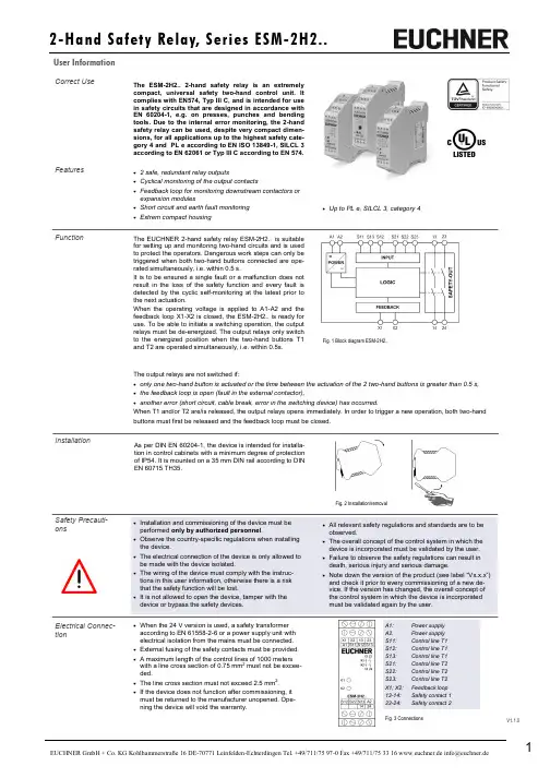
• Up to PL e, SILCL 3, category 4Correct UseThe ESM-2H2.. 2-hand safety relay is an extremely compact, universal safety two-hand control unit. It complies with EN574, Typ III C, and is intended for use in safety circuits that are designed in accordance with EN 60204-1, e.g. on presses, punches and bending tools. Due to the internal error monitoring, the 2-hand safety relay can be used, despite very compact dimen-sions, for all applications up to the highest safety cate-gory 4 and PL e according to EN ISO 13849-1, SILCL 3 according to EN 62061 or Typ III C according to EN 574.Features• 2 safe, redundant relay outputs• Cyclical monitoring of the output contacts• Feedback loop for monitoring downstream contactors orexpansion modules• Short circuit and earth fault monitoring • Extrem compact housingFunctionThe EUCHNER 2-hand safety relay ESM-2H2.. is suitable for setting up and monitoring two-hand circuits and is used to protect the operators. Dangerous work steps can only be triggered when both two-hand buttons connected are ope-rated simultaneously, i.e. within 0.5 s.It is to be ensured a single fault or a malfunction does not result in the loss of the safety function and every fault is detected by the cyclic self-monitoring at the latest prior to the next actuation.When the operating voltage is applied to A1-A2 and the feedback loop X1-X2 is closed, the ESM-2H2.. is ready for use. To be able to initiate a switching operation, the output relays must be de-energized. The output relays only switch to the energized position when the two-hand buttons T1 and T2 are operated simultaneously, i.e. within 0.5s.Fig. 1 Block diagram ESM-2H2..InstallationAs per DIN EN 60204-1, the device is intended for installa-tion in control cabinets with a minimum degree of protection of IP54. It is mounted on a 35 mm DIN rail according to DIN EN 60715 TH35.Fig. 2 Installation/removalElectrical Connec-tion• When the 24 V version is used, a safety transformeraccording to EN 61558-2-6 or a power supply unit with electrical isolation from the mains must be connected. • External fusing of the safety contacts must be provided. •A maximum length of the control lines of 1000 meters with a line cross section of 0.75 mm 2 must not be excee-ded.•The line cross section must not exceed 2.5 mm2. •If the device does not function after commissioning, it must be returned to the manufacturer unopened. Ope-ning the device will void the warranty.A1: Power supply A2. Power supply S11: Control line T1 S12: Control line T1 S13: Control line T1 S21: Control line T2 S22: Control line T2 S23: Control line T2 X1; X2: Feedback loop 13-14: Safety contact 1 23-24:Safety contact 2The output relays are not switched if:• only one two-hand button is actuated or the time between the actuation of the 2 two-hand buttons is greater than 0.5 s, • the feedback loop is open (fault in the external contactor),• another error (short circuit, cable break, error in the switching device) has occurred.When T1 and/or T2 are/is released, the output relays opens immediately. In order to trigger a new operation, both two-hand buttons must first be released and the feedback loop must be closed.ESM-2H2..The arrangement of the two-hand buttons must be designed in accordance with the standard EN 574 such that accidental actuation or simple bypassing of the safety function is excluded.The ESM-2H2.. unit is provided for the connection of 2-hand push-buttons, with one normally open or one normally colsed contact.Figur 1 shows the wiring of the ESM-2H2.. with a 2-hand push-buttons:ApplicationsFig. 1:Wiring of the ESM-2H2.. with a 2-hand push -buttonsFig. 2: Feedback loopContactors connected to the ESM-2H2.. or the basic devices are monitored via the feedback loop of the basic device. K A and K B are the positively driven contacts of the connected contactor or expansion module.Feedback loopNote: The items listed under “Electrical connection” must be observed during commissioning. Commissioning Procedure1. Wiring ESM-2H2..:Wire the ESM-2H2.. With the 2-hand push button according to your application (see Fig. 1).2. Wiring feedback loop:Wire the feedback loop as shown in Fig. 2.3. Wiring power supply:Connect the power supply to terminals A1 and A2.Warning: Wiring only in de-energized state.4. Starting the device:Switch the operating voltage on.5. Switch to working condition:Press the two buttons T1 and T2 simultaneously, or within 0.5 seconds.The positive-guided relay switches.6. Switch into hibernation:Release the two buttons T1 and T2. The positive-guided relay swiches off.Jumper X1-X2: See descriptionX1 X2InstallationAvoiding unintentional actuation or bypassing of the safety deviceThe arrangement of the two-hand buttons must be designed in accordance with the standard EN 574 such that accidental actuation or simple bypassing of the safety function is excluded.The operation of both buttons using one hand must be prevented by an adequate distance (at least 260 mm) or by a sepa-rating wall. Actuation using forearm, elbow, knee, hip or other parts of the body can be effectively prevented by a further increase in the distance between the two buttons, adequate distance from the floor and/or covers and/or separating walls. Distance from the two-hand buttons to the danger areaIt is necessary to maintain a minimum distance between the buttons for the two-hand circuit and the danger area on themachine or plant so that, after the release of one or both buttons, the machine or plant can only be reached once the dange-rous movement has been interrupted or completed. According to the standard DIN EN ISO 13855, the distance is calculated with the following equation:S = (K · T) + CS : Minimum distance from the nearest pushbutton (two-hand button) to the danger area.K : Parameter in mm/s, derived from data on the approach speeds of the body or parts of the body, for two-hand circuits 1600 mm/s.T : The overtravel of the overall system in seconds, that is the time from releasing the two-hand button to the end of the dan gerous movement.C : Additional distance in mm that based on entry into the danger area prior to the triggering of the safety device. For twohand circuits this is 250 mm, this distance can also be set to 0 mm given an adequate cover on the buttons, however then S must be at least 100 mm.ExampleThe overtravel time for the entire system is 90ms. Then the above equation gives for the minimum distance: S = (1600 mm/s · 0.09 s) + 250 mm S = 144 mm + 250 mm = 394 mmIf a suitable cover is used, S can be reduced to 144mm (see above).MaintenanceWhat to Do in Once per month, the device must be checked for proper function and for signs of tampering and bypassing of the safety function (to do this, check the wiring of the device and activate the emergency stop function. Check the delay time).The device is otherwise maintenance free, provided that it was installed properly.Note:Additional data can be requested from the manufacturer for applications that deviate from these conditions.SafetyCharacteristics According to EN ISO 13849-1The device is certified according to EN ISO 13849-1 up to a Performance Level of PL e.Safety characteristics according to EN ISO 13849-1 for all variants of ESM-2H2.. Load (DC-13; 24 V) <= 0.1 A <= 1 A <= 3 A T10d [years] 20 20 20 Category: 4 4 4 PLe e e PFHd [1/h]: 1.2E-08 1.2E-08 1.2E-08 nop [cycle / year]<= 400,000<= 100,000<= 22,500Case of a Fault?If the fault still exists, perform the steps listed under “Commissioning Procedure”.If these steps do not remedy the fault either, return the device to the manufacturer for examination.Opening the device is impermissible and will void the warranty.Device does not switch on:• Check whether the 2-hand button of correct function. • Check whether the wiring.• Check the supply voltage on A1 and A2 • Is the feedback loop closed?Dimension DrawingS u b j e c t t o t e c h n i c a l m o d i f i c a t i o n s , n o r e s p o n s i b i l i t y i s a c c e p t e d f o r t h e a c c u r a c y o f t h i s i n f o r m a t i o n . © E U C H N E R G m b H + C o . K G 109071-06-02/16 (T r a n s l a t i o n o f t h e O r i g i n a l O p e r a t i n g I n s t r u c t i o n s ) Fixed TerminalsPlug-In Terminals。
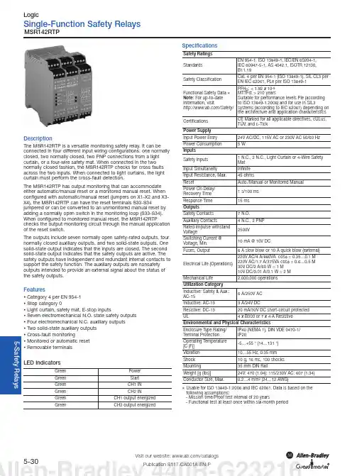
Single-Function Safety Relays5-30Visit our website: /catalogsPublication S117-CA001A-EN-PMSR142RTPDescriptionThe MSR142RTP is a versatile monitoring safety relay. It can be connected in four different input wiring configurations: one normally closed, two normally closed, two PNP connections from a light curtain, or a four-wire safety mat. When connected in the two normally closed fashion, the MSR142RTP checks for cross faults across the two inputs. When connected to light curtains, the light curtain must perform the cross-fault detection.The MSR142RTP has output monitoring that can accommodate either automatic/manual reset or a monitored manual reset. When configured with automatic/manual reset (jumpers on X1-X2 and X3-X4), the MSR142RTP can have the reset terminals S33-S34 jumpered or can be converted to an unmonitored manual reset by adding a normally open switch in the monitoring loop (S33-S34). When configured to monitored manual reset, the MSR142RTP checks the output monitoring circuit through the manual application of the reset switch.The outputs include seven normally open safety-rated outputs, four normally closed auxiliary outputs, and two solid-state outputs. One solid-state output indicates that the inputs are closed. The second solid-state output indicates that the safety outputs are active. The safety outputs have independent and redundant internal contacts to support the safety function. The auxiliary outputs are nonsafety outputs intended to provide an external signal about the status of the safety outputs.FeaturesCategory 4 per EN 954-1Stop category 0Light curtain, safety mat, E-stop inputsSeven electromechanical N.O. state safety outputsFour electromechanical N.C. auxiliary outputsTwo solid-state auxiliary outputsCross-fault monitoringMonitored or automatic resetRemovable terminalsLED IndicatorsGreen PowerGreen StartGreen CH1 INGreen CH2 INGreen CH1 output energizedGreen CH2 output energized SpecificationsSafety RatingsStandardsEN 954-1, ISO 13849-1, IEC/EN60204-1,IEC60947-5-1, AS4042.1, ISOTR12100,B11.19Safety ClassificationCat. 4 per EN 954-1 (ISO 13849-1), SIL CL3 perEN IEC 62061, PLe per ISO 13849-1Functional Safety Data 1Note: For up-to-dateinformation, visit/Safety/PFH D: < 1.92 x 10⁻⁹MTTFd: > 210 yearsSuitable for performance levels Ple (accordingto ISO 13849-1:2006) and for use in SIL3systems (according to IEC 62061) depending onthe architecture and application characteristics CertificationsCE Marked for all applicable directives, cULus,TÜV, and c-TickPower SupplyInput Power Entry24V AC/DC, 115V AC or 230V AC 50/60 Hz Power Consumption 5 WInputsSafety Inputs1 N.C.,2 N.C., Light Curtain or 4-Wire SafetyMatInput Simultaneity InfiniteInput Resistance, Max.45 ohmsReset Auto./Manual or Monitored ManualPower On Delay/Recovery Time1 s/100 msResponse Time15 msOutputsSafety Contacts7 N.O.Auxiliary Contacts 4 N.C., 2 PNPRated Impulse withstandVoltage2500VSwitching Current @Voltage, Min.10 mA @ 10V DCFuses, Output 6 A slow blow or 10 A quick blow (external) Electrical Life (Operations)220V AC/4 A/880VA cosφ= 0.35…0.1 M220V AC/1.7 A/375VA cosφ= 0.6…0.5 M30V DC/2 A/60 W = 1 M10V DC/0.01 A/0.1 W = 2 MMechanical Life2,000,000 operationsUtilization CategoryInductive: Safety & Aux.:AC-156 A/250V ACInductive: AC-13 3 A/24V DCResistive: DC-1320 mA/30V DC short-circuit protectedUL 4 x B300 or 7 x 4 A ResistiveEnvironmental and Physical CharacteristicsEnclosure Type Rating/Terminal ProtectionIP40 (NEMA 1), DIN VDE 0470-1/IP20Operating Temperature[C(F)]-5…+55° (14…131°)Vibration10…55 Hz, 0.35 mmShock10 g, 16 ms, 100 shocksMounting35 mm DIN RailWeight [g (lbs)]24V: 470 (1.04); 115/230V AC: 607 (1.34) Conductor Size, Max.0.2…4 mm2(24…12 AWG)1Usable for ISO 13849-1:2006 and IEC 62061. Data is based on the following assumptions:- Mission time/Proof test interval of 20 years- Functional test at least once within six-month periodSingle-Function Safety Relays5-31Visit our website: /catalogsMSR142RTP5-S a f e t y R e l a y sProduct SelectionAccessoriesDimensions are shown in mm (in.). Dimensions are not intended to be used for installation purposes.Block DiagramTypical Wiring DiagramsL1K1L2L3MActiveClosedLIght Curtain, Monitored Manual Reset,Monitored Output Single Channel Safety Gate, Auto Reset,No Output MonitoringL1K1L2K2L3M+24V DCActiveClosedDual Channel E-Stop, Monitored Manual Reset, Monitored Output Safety Mat, Automatic Reset, No Output MonitoringApproximate DimensionsSafety Applications and Wiring DiagramsSafety Valve & E-Stop—Air Supply Release10-30Visit our website: /catalogsPublication S117-CA001A-EN-P800F, MSR142, Pneumatic Safety ValveCircuit StatusThe e-stop button is released, the MSR142 safety relay outputs are off and the pneumatic valve is closed.Operating PrincipleSTARTING: Press the reset button to energize the output contacts of the safety relay. The two solenoids in the valve energize and allow air to flow from the Air Supply to the Air Outlet.STOPPING: Pressing the e-stop button de-energizes the safety outputs of the MSR142, which in turn drops out the solenoids of the safety valve. The valve closes the Air Supply and releases the air pressure to the Air Exhaust. Releasing the e-stop button does not cause the valve to turn back on.Fault DetectionUpon successful completion of internal checks on power up, the MSR142 checks the e-stop status. If an open or short circuit is detected, the MSR142 will not energize its outputs. If both input circuits are properly closed, the MSR142 checks the status of the safety valve. If one or both solenoids of the safety valve are energized, the Status contact will be open, and the MSR142 will not energize its outputs. If both solenoids are de-energized, Status contact will be closed and the MSR142 will turn on its Ready LED. Pressing the Reset button energizes the MSR142 safety outputs and opens the safety valve.The safety valve performs its own internal checks. If one of the valves remains actuated, gets stuck or moves too slowly, the Air Outlet flow will be re-directed to the exhaust. To clear the fault condition, both valves must be de-energized and the valve reset button pressed.+24V DCRatingsThe safety function initiated by the 800F e-stop button meets the safety performance requirements of SIL CL 3 per IEC 62061:2005 and has Category 4structure that can be used in systems requiring Performance Levels up to PLe per ISO 13849-1: 2006. The MSR142 has seven safety rated outputs. To maintain the highest safety levels, these outputs must drive redundant actuators which must be monitored for proper performance. This example circuit performs a Stop Category 0 function (coast to stop).Allen-Bradley 440R-G23216。
Release NotesOriginal InstructionsGuardmaster 440C-CR30 Safety Relay, Revision 11Catalog Number 440C-CR30-22BBBSummary of ChangesThis publication contains the following new or updated information. This list includes substantive updates only and is not intended to reflect all changes.About This PublicationThese release notes supplement the existing documentation supplied with your product. Read this document before using Guardmaster® 440C-CR30 safety relays.Firmware Revision HistoryAvailability of Enhancements and Anomaly FixesEnhancements are available in the safety relay only if it is at the required firmware revision or higher and the Connected Components Workbench™ or Studio 5000 Logix Designer® project contains a safety relay that is configured with the required firmware revision or higher. If the project contains a safety relay revision that is lower than the required revision for an enhancement, then the project is still valid but the enhancement will not be available until the project is upgraded to the minimum supported revision.Fixes for firmware anomalies are available as long as the safety relay firmware revision is at the minimum revision or higher. The configured safety relay revision must be of the same major revision.The following tables provide a list of enhancements, known anomalies, and corrected anomalies for the CR30 safety relay firmware revisions.EnhancementsTopicPage Updated Firmware Revision History 1Updated Table 22Updated image in step 23Revision Description6.004First revision release [safety firmware 0A.01]6.006Minor revision release [safety firmware 0A.02]7.006Major revision release [safety firmware 0A.02]8.013Major revision release [safety firmware 0A.02]9.004Major revision release [safety firmware 0A.02]10.004Major revision release [safety firmware 0A.03]10.009Minor revision release [safety firmware 0A.03]10.010Minor revision release [safety firmware 0A.03]10.011Minor revision release [safety firmware 0A.03]Table 1 - EnhancementsEnhancement (1)DescriptionAvailable From Firmware RevisionLock control function support New Lock Control function is now supported forissuing an unlock request to a safety gate withguard locking.10.004Mode selection function support New Mode Selection Safety Monitoring Function is now supported.10.004Mute function enhancements New Muting function block has been enhanced to support a mute enable input, a mute fault manual monitored reset and now offers a secondary output based on the override status.10.004Status function supportNew Status functions for monitoring andannunciating function block faults or ‘waiting for reset’ conditions.10.004Reusable feedback supportNew ability to apply feedback inputs to multiple Safety Output Functions.10.004Single input And withRestartenhancement New ability for the And with Restart logic function to support one input.10.004PanelView Plus Tag browsing support With release 8.00 of FactoryTalk® View Studio, PanelView™ Plus can communicate to CR30 safety relays using EDS parameter browsing over EtherNet/IP™.9.004Nesting of Logic Level Function blocksNew ability to use the output state of a logic block immediately above another logic block as an input condition.9.004Inverting of Logic Level Inputs/Outputs New ability to invert (logical NOT) of inputs and outputs of Logic Level function blocks.9.004Output Loop Safety Monitoring Function support New Output Loop Safety Monitoring Function that allows the logical state of a Safety Output Function to be used as an input condition.9.004RS Flip-Flop Logic Function support New RS Flip-Flop Logic function is now supported in the Logic level columns of the Logic Editor.9.004440C-ENET plug-in supportThe EtherNet/IP plug-in provides both I/O messaging and explicit messaging. The safety relay can now be configured over EtherNet/IP using either Connected Component Workbench or an Add-on Profile (AOP) in Studio 5000 Logix Designer application.8.013Standard Signal Safety Monitoring Function support New Standard Signal Safety Monitoring Function that allows the use of standard control signals from digital plug-ins or communication ports to be used in the logic of the safety relay.8.013Project Upgrade featureProjects developed for earlier versions of firmware can be automatically converted into the latest version of firmware supported.8.0132080-MEMBAK-RTC plug-in support Project backup and restore are supported on CR30 safety relays through the 2080-MEMBAK-RTC module.7.0062080-IQ4 plug-in supportThe 2080-IQ4 digital input plug-in provides 4-pt standard rated 12/24V DC digital input expansion. It can be used in slot 1 and/or slot 2 module bays.7.0062Rockwell Automation Publication 440C-RN001H-EN-P - December 2020Guardmaster 440C-CR30 Safety Relay, Revision 11 Release NotesAnomalies2080-OB4 plug-in support The 2080-OB4 digital output plug-in provides 4-pt standard rated 12/24V DC sourcing output expansion. It can be used in slot 1 and/or slot 2 module bays.7.0062080-OW4I plug-in supportThe 2080-OW4I relay output plug-in provides 4-pt standard rated relay output, individually isolated, 2A expansion. It can be used in slot 1 and/or slot 2 module bays.7.006Unique function block name supportUnique names can be assigned to the Safety Monitoring Function blocks and the Safety Output Function blocks. These names are stored in the project that is loaded to the safety relay and can be recovered by an upload.7.006Password protection Software connections including Upload, Download,and Connect can be restricted through passwordprotection.7.006(1)For more information, see publication 440C-UM001.Table 2 - Known and Corrected AnomaliesAnomalyDescriptionAffected Firmware Revisions Corrected Firmware Revision Discrepancy Fault on Power-upDevices with pulse testing outputs would sometimes cause a discrepancy fault in the CR30 safety relay upon power-up. On power-up, the Channel Test during the first logic scan when transitioning from self-test to run mode has been removed to help prevent the discrepancy fault.See publication 440C-UM001 for details.6.0046.0067.0068.0139.00410.00410.00910.01010.011Memory Module Incompatibility Safety relay fails to recognize 2080-MEMBAK-RTC memory modules that are manufactured on or after 2016/02/11.APBC000280011 6.0046.0067.0068.0139.00410.00410.00910.010Memory Module Update When updating a safety relay from a previous firmware revision to firmware 10 using thememory module the restore operation must be performed twice (the first process updates thefirmware, the second process restores the user configuration). 6.004 6.0067.0068.0139.004Configuration loss on power cycleDuring specific power down conditions, the safety relay could be interrupted while writing a fault condition to its nonvolatile memory. On power up, the memory is evaluated as corrupted and the user configuration is discarded.APBC00026898 6.0046.0067.0068.0139.00410.00410.009Connection failure with Add-on Profile (AOP) major revision 1The safety relay rejects an I/O connection that originates from the safety relay AOP (versions 1.013 and versions 1.014) when Compatible Keying and Major Revision 8 or later is configured.APBC000271569.00410.004Download faultA download could result in a major fault on the safety relay, Type 06, Code 20 – Configuration Fault.APBC000251087.0068.0139.00410.004Download over Ethernet faultA download over Ethernet to the safety relay could result in a Type 05, Code 00 – Internal Safety Synch Fault.APBC000236608.0139.00410.004Unexpected disconnect from safety relay Occasionally Connected ComponentsWorkbench software would unexpectedly disconnect while connected to a password protected safety relay.APBC000248668.0139.004Table 1 - Enhancements (Continued)Enhancement (1)DescriptionAvailable From Firmware RevisionLocked by another connection error Attempts to connect to the safety relay arerejected and erroneously reports “CR30 has been locked by another, new connection is not allowed.”APBC000248678.0139.004No reconfiguration after EEPROM fault After the safety relay experiences a memory fault (Type 5 Code 00), the safety relay does not accept a new download.APBC00024866 6.0046.0067.0068.0139.004Muting L-Type reports incorrect fault description Under specific configuration conditions, the Muting T Type function block incorrectly reports a mute sensor timing fault when actually a sequence fault occurred.APBC000237318.0139.004Network address changes require power cycle Changes to the 440C-ENET Ethernet portsettings, duplicate IP address detection, and DHCP vs. static IP address settings may require a power cycle to take effect.APBC000241338.0139.004Power-up faultVariations in 24V DC supply power to the CR30 safety relay during power-up could lead to power fault: Type 04, Code 01.APBC000244266.0046.0067.0068.013Discrepancy fault after power-upVariations in 24V DC supply power to the CR30 safety relay during power-up could lead to adiscrepancy fault on any dual channel Safety Monitoring Function: “One channel open after reset” 6.0046.0067.0068.013Empty fault logModbus reporting of the fault log always returns 0, indicating no fault, even if faults are present in the log.APBC00025011 6.0046.0067.0068.013Incorrect Mode The safety relay will return to Run Mode after downloading a valid configuration to a unit that has experienced a nonrecoverable fault.APBC000257716.0046.0067.0068.013Modbus fault state cleared in Program Mode The safety relay does not report faultinformation over Modbus once the safety relay is placed in Program Mode.6.0046.0067.0068.013Memory module firmware update failure The memory module is unable to upgrade a firmware revision 7 safety relay to version 8 or later 7.006L-Type muting override conditionOverride for L-Type muting cannot be initiated when only the light curtain is interrupted (no mute sensors).6.0046.0067.006Two Hand Control at power up Two Hand Control does not fault at power up if buttons are pressed. 6.0046.0067.006Override conditionsFor muting applications, mute sensor interrupted or timing faults should be only conditions that allow override to be initiated.6.0046.0067.006Serial port doesnot shutdownWhen the serial port is configured as shutdown,it still responds to Modbus messages.APBC00020590 6.0046.0067.006Input filters greater than 200 ms create nonrecoverable fault When an input filter of greater than 200 ms is configured on any Safety Monitoring function, a nonrecoverable fault is generated when the configuration is downloaded to the safety relay.APBC00020589 6.0046.0067.006Missing plug-in slot 1 without fault log entry A missing plug-in module configured in slot 1 and not actually present results in a fault but no fault log entry is created.APBC00018493 6.0046.0067.006Plug-inmismatch with duplicate fault log entriesA mismatch between the plug-in present on slot 1 and the actual plug-in present results in duplicate entries in the fault log.APBC000205086.0046.0067.006Plug-in outputs fail to configure When Plug-in outputs terminals are selected asoutputs for Safety Output Functions, they fail toturn on when the corresponding Safety OutputFunction turns on.APBC000201036.004 6.006Table 2 - Known and Corrected Anomalies (Continued)AnomalyDescriptionAffected Firmware Revisions Corrected Firmware RevisionRockwell Automation Publication 440C-RN001H-EN-P - December 20203Guardmaster 440C-CR30 Safety Relay, Revision 11 Release NotesUse DMK FilesFirmware for the CR30 safety relay beginning with firmware revision 10.009 uses a new file format called *.DMK. These files are named for easy identification, for example: 440C-CR30-22BBB_10.009.dmk.ControlFLASH™ software, version 13 or later, supports the format. ControlFLASH software is automatically installed as part of Studio 5000 Logix Designer application installation, version 28 or later. You can download ControlFLASH software from the Rockwell Automation Product Compatibility and Download Center (PCDC - rok.auto/pcdc ) separately, if necessary.You are not required to install the new firmware file format. When you download *.DMK files from the Rockwell Automation PCDC, ControlFLASH softwareautomatically saves the folder location where the *.DMK files were downloaded. As a result, ControlFLASH software can easily locate *.DMK files.You can use the Browse option to access and configure the folders that ControlFLASH software monitors as shown:Upgrade Safety Relay FirmwareThis procedure shows you how to update the firmware in a CR30 safety relay using ControlFLASH. To download the latest CR30 safety relay firmware revision, go to the PCDC (PCDC - rok.auto/pcdc ) and select your desired revision.On CR30 safety relays, you can upgrade your safety relays through the Ethernet port on the 440C-ENET plug-in module and the USB.Through USB1.Verify successful RSLinx® Classic communications with you CR30 safety relay by USB using RSWho. The CR30 safety relay uses the AB_VBP-x driver.2.Start ControlFLASH (Start > All Programs > FLASH Programming Tools > ControlFlash) and click Next >.3.Select the catalog number of the CR30 safety relay (440C-CR30-22BBB) that you are updating and click Next >.4.Select the safety relay in the browse window and click OK.Communication fault without fault log entryIf the host microprocessor within the CR30safety relay loses communication with the safety processors a fault is generated but no fault log entry is createdAPBC00020302 6.0046.006Fault log index changes after power cycleAfter a power cycle of the safety relay,previously detected faults index by one within the fault log.APBC000186376.004 6.006Inverted image of downloadprogram notcompared After performing a download, the inverted datais sent back from the safety relay to Connected Components Workbench software but not compared as an additional diagnostic check.APBC00020430 6.004 6.006Download through virtual image failsDownload of a program to the safety relay occasionally fails due to connection timeout when downloading through a virtual image.6.004 6.006ATTENTION: All Ethernet settings are reverted to factory default after a ControlFLASH firmware update.Table 2 - Known and Corrected Anomalies (Continued)AnomalyDescriptionAffected Firmware Revisions Corrected Firmware Revision IMPORTANTTo update your safety relay successfully, it must be in Program Mode or BOOT Loader mode. The safety relay can be placed into Program Mode from the Graphic Overview screen in Connected Component Workbench software, the Logic Configuration tab in the Logix Designer module profile or placed in BOOT Loader mode by holding the MEM/ID button located below the USB port on the safety relay during power-up.Publication 440C-RN001H-EN-P - December 2020 | Supersedes Publication 440C-RN001G-EN-P - April 2016Copyright © 2020 Rockwell Automation, Inc. All rights reserved. Printed in the U.S.A.Rockwell Otomasyon Ticaret A.Ş. Kar Plaza İş Merkezi E Blok Kat:6 34752 İçerenköy, İstanbul, Tel: +90 (216) 5698400 EEE Yönetmeliğine UygundurAllen-Bradley, Connected Components Workbench, ControlFLASH, expanding human possibility, FactoryTalk, Guardmaster, PanelView,Rockwell Automation, RSLinx, and Studio 5000 Logix Designer are trademarks of Rockwell Automation, Inc.EtherNet/IP is a trademark of ODVA, Inc.Trademarks not belonging to Rockwell Automation are property of their respective companies.Your comments help us serve your documentation needs better. If you have any suggestions on how to improve our content, complete the form at rok.auto/docfeedback .For technical support, visit rok.auto/support.Waste Electrical and Electronic Equipment (WEEE)Rockwell Automation maintains current product environmental compliance information on its website at rok.auto/pec .At the end of life, this equipment should be collected separately from any unsorted municipal waste.5.Verify the revision, and click Next > to continue.6.Click Finish.7.Click Yes to initiate the update.The next screen shows the download progress.If you see the following error message, verify that the safety relay is in Run mode. If so, change to Program or BOOT Loader mode by pressing theMEM/ID switch during power-up of the CR30 safety relay, click OK, and try again.When the update is complete, you see a screen similar to the following.Click OK to complete the update.。
航海及海运专业英语词汇(S1)s chair 双套结s point 船首基线s seconds signs silvers slips slows starboards switchs-bend s形弯管s-generation 第二代s-hook s形钩s-link s形连接件s-pole s极s-shackle s形卸扣s-wrench s形扳手s.s.s. clutch 自动同步滑动离合器sa safe arrivalsa subject to approvalsaaret 岛saari saaret 群)岛saari 岛sabathecycle 等容等压混合加热循环sabik =ηophiuchi 宋sables 黑貂皮sabotage 破坏sabotage 破坏的行为;怠工sac 袋状凹湾sack cargo 袋装货sack conveyor 袋装货运输带sack of coals 麦哲伦云sack 包布袋sack 包布袋袋装材料sack 布袋sack 袋sack 装sack-cloud 麦哲伦云sacriffice of ship 牺牲船舶sacrifice of cargo 货物牺牲sacrifice of freight 运费牺牲sacrifice of ship 牺牲船舶sacrifice property 牺牲财产sacrifice 牺牲sacrifice 牺牲;亏本出售sacrificial anode cathodic protection 牺牲阳极阴极保sacrificial anode protection 牺牲阳极法sacrificial anode 牺牲阳极sacrificial anodic protection 牺牲阳极保sacrificial corrosion 阴极保腐蚀sacrificial 牺牲的saddle back 鞍板saddle cut-out 鞍座断流器saddle hatch 鞍形舱口saddle hatch 鞍形舱口saddle joint 鞍架接合saddle key 鞍形键saddle plate 鞍板saddle seat 鞍座saddle support 鞍形支承saddle 鞍;鞍形物;凹座;凹谷;鞍型低压;圆枕木锅炉座saddle 海底鞍形支架saddle 支架saddlehill 马鞍峰sae number sae号数sae viscosity sae粘度sae 汽车工程师学会safe access 船内安全通道safe aground 安全搁浅safe allowable load 安全容许载荷safe allowable load 安全许可载荷safe allowable stress 安全容许应力safe allowable stress 安全许用应力safe anchorage 安全锚地safe arrival 安全到达safe arrival 安全抵达safe berth clause 安全泊位条款safe berth 安全泊位safe berth 安全泊位安全锚泊safe berth 安全锚泊safe carriage of grain 谷物安全装运safe carriage 安全运载safe carrying capacity 安全载流量safe conduct 安全条例safe container 安全集装箱safe current carrying capacity 安全载流量safe current 安全电流safe deck load height 上甲板载货安全高度safe design 安全设计safe distance of approachsafe distance of approach会遇安全距离safe distance 安全距离safe drip pan 承油盘safe factor 安全系数safe guard 保safe handling of cargo 货物安全装卸safe handling of dangerous goods 危险货物的安全装卸safe handling 安全操作safe handling 安全运转safe haven 安全的避风港safe injection 安全喷射safe limit 安全界限safe load calculator 配载仪safe load 安全负载力safe load 安全载荷safe loading 安全装载safe management and operation of ship 船舶安全管理和操作safe management of ship 船舶的安全管理safe navigable speed 安全航速safe navigation 安全航行safe navigational procedure 安全导航程序safe offing 为安全而驶出海面safe operation area of loading or discharging of dangerous goods 危险货物装卸安全作业区safe operation 安全操作safe operation 安全运行safe operation 安全运营safe operation 安全作业safe overhead clearance 安全净空高度safe passing 安全通过safe place 安全地点safe port 安全港safe port 安全港口safe prosecution of voyage 安全完成航程safe prosecution of voyage 安全续航safe range of stress 安全应力范围safe reliability 安全可靠性safe roadstead 安全锚地safe securing 安全系固safe shipment 安全载运safe shut-down 安全停safe speed 安全航速safe storage of dangerous goods 危险货物的安全存放safe stowage 安全积载safe stress 安全应力safe transport of dangerous goods 危险货物的安全运输safe transport 安全运输safe voltage 安全电压safe water mark 安全水域标志safe water marks 安全水域标safe working load 安全负载力safe working load 安全工作负荷safe working load 安全工作载荷safe working load 安全使用负荷safe working load 安全有效载荷safe working pressure 安全工作压力safe working strength 安全工作强度safe working stress 安全工作应力safe working temperature 安全工作温度safe 安全的safe-load computer 安全负载计算机safe-working load 安全工作载荷safeguard and alarm 保措施和报警器safeguard clause 保障条款safeguard 安全设备safeguard 保装置safeguard 保险板safeguarding duties 保性关税safekeeping fee 保管费safekeeping life 安全储存期限safekeeping 保safekeeping 保妥善保管safekeeping 妥善保safest 最安全的safety alarm 安全报警器safety allowance 安全裕量safety ampparatus 安全装置safety and interlock device 安全联锁装置safety and limit control 安全和极限控制safety and limit protection 安全和极限保safety angle 安全角safety apparatus 安全装置safety appliance 安全设备safety approval plate 安全合格牌照safety assessment 安全鉴定书safety assurance system 安全保证系统safety at sea international 《国际海上安全》safety at sea 海上安全safety basin 安全水域safety belt 安全带safety bolt 安全螺栓safety brake 安全闸safety brake 安全制动器safety buoy 救生圈safety buoyancy 储备浮力safety buoyancy 预备浮力safety call 安全呼叫safety cap 安全帽safety car 救生吊车safety catch 安全掣子safety catch 保险扣safety certificate 安全证书safety chain 安全链safety chain 安全链备用电路safety chain 备用电路safety clamp 安全夹safety clearance 安全间隙safety clip 熔断器接线端safety clip 熔丝夹safety clntrol 安全控制safety clutch 安全离合器safety cock 安全旋塞safety code 安全码safety coefficient 安全系数safety collar 安全环safety communication 安全通信safety construction certificate 安全构造证书safety construction certificate 安全结构证书safety control 安全保障safety coupling 安全联轴节safety coupling 安全联轴器safety cup 安全帽safety cut-off 安全开关safety cut-out device 安全切断装置safety cut-out 安全断流器safety cut-out 保安器safety cutout circuit 安全断开电路safety deck 安全甲板safety device 安全装置safety dog 安全轧头safety earthing 安全接地safety earthing 保接地safety engineering 安全工程技术safety equipment certificate 安全设备证书safety equipment certificate 安全设备证书安全设备证书safety equipment certificate 设备安全证书safety equipment 安全设备safety et screw 安全止动螺钉safety exhaust 安全排气阀safety factor 安全系数safety factor 安全因数safety fairway 安全航道safety falling velocity 安全降落速度safety feature test 安全性能试验safety flap 安全瓣safety fuel 安全燃料safety fuse 保险丝safety gear 安全装置safety glass 不碎玻璃safety goggles 安全护目镜safety governor 安全调速器safety guard 安全板safety guard 保险板safety hardener 安全固化剂safety hatch 安全舱口safety hatch 太平舱口safety height of ullage 油面安全高度safety hook 安全钩safety injection system 安全注射系统safety inspection of vessels in inland waters 内河船舶安全检查safety inspection 安全检查safety interlock for running direction 转向安全联锁装置safety interlock 安全联锁装置safety keel 龙骨翼板safety lamp 安全灯safety latch hook 自锁安全吊货钩safety latch 安全闩safety law 安全规则safety lever 保险杆safety lighting 安全照明safety limit 安全界限safety line 安全绳索safety line 安全索safety load 安全负荷safety load 安全载荷safety locker 保险箱safety locking wire 安全锁线safety loop 保险圈safety management system 安全管理系统safety margin 安全余地safety margin 安全裕度safety match 安全火柴safety measure 安全措施safety measures 安全措施safety mechanism 安全机构safety mechanism 保险机构safety meeting 两船安全会遇safety message 安全信文safety net provision10% 安全网条款safety net 安全网safety net 安全网;安全信息网safety net 保网safety nut 安全螺母safety of crew 船员安全safety of human life 人命安全safety of life at sea 海上人命安全safety of life of person on board 船上人命安全safety of maritime navigation 航海安全safety of navigation 航行安全safety of property at sea 海上财产安全safety of ship 船舶安全safety of ships law 船舶安全法safety officer 安全员safety pad 安全垫safety passing distance 安全通过距离safety performance 安全性能safety pin 安全销safety plug socket 安全塞座safety plug 保险塞safety plug 插塞式熔断器safety pole 安全杆safety precaution 安全防护safety precaution 安全预防措施safety protection program 安全保程序safety protection system 安全保装置safety provision 安全措施safety radiotelegraphy certificate 无线电设备安全证书safety radiotelephony certificate 无线电话安全证书safety rail 安全栏杆safety rail 安全拦杆安全栏杆safety regulation 安全调节safety regulations for offshore installations 海上平台安全规则safety regulations 安全规程safety relay 保安继电器safety requirement 安全要求safety ring 安全环safety ring 保险环safety rod 安全棒safety rope 安全绳safety rules 安全条例safety service 安全业务safety set screw 安全止动螺钉safety signal 安全信号safety slip clutch 安全滑动离合器safety spark gap 安全火花间隙safety speed 安全速度safety standard 安全标准safety standards 安全标准safety stay 安全牵条safety stop device 安全止动装置safety stop 安全限制器safety stop 安全止动器safety supervision department 安全监督处safety support vessel 安全支持船safety switch 安全开关safety switch 保险开关safety system 安全保系统safety tackle 安全绞辘safety tap 安全旋塞safety temperature 安全温度safety traffic 安全通信safety tread 防滑板safety trip level 保安断路水平safety trip 安全脱口器safety type dispensing valve 安全型分配阀safety valve complement 安全阀总成safety valve operation test 安全阀调整试验safety valve setting 安全阀压力较定safety valve spring 安全阀弹簧safety valve 安全阀safety voltage 安全电压safety washer 安全垫圈safety working boots 安全工作靴safety working shoes 安全工作鞋safety zone 安全区safety 安全safety 可靠性safety-type panel 安全型配电板safty construction certificate 《安全结构证书》safty fairway 安全航道sag resistance 拖索中垂阻力sag to leeward 向下风漂流sag 下垂sag 下陷下沉sag 中垂;下降;倾斜;垂弛;垂度;压向下风sagging condition 中垂状况sagging condition 中垂状态sagging gaff 向下风舷侧斜的斜桁sagging moment 中垂力矩sagging stress 中垂应力sagging stresses 中垂应力sagging 流挂;中垂sagging 弯曲sagging 下垂sagging 中垂sagittarius = archer 人马星座sagittarius 人马星座said by shipper to contain 内容据发货人报称said to be 1 000 mts 重量据称为1千公吨said to be 据称said to contain 据说装有said to weigh 据称重量;自报重量said to weigh 据说重量said to weight 据称重量sail angle 帆角sail area 帆面积sail area 受风面积sail assisted ship 风帆船sail bag 风帆罩sail batten 硬帆横支撑条sail before the mast 普通水手sail broad 顺风驶帆sail cabin 帆具舱sail cloth 帆布sail free 顺风驶帆sail ho! 看见船了!sail hook 缝帆钩sail in ballast 压载航行sail in 入港sail large 顺风驶帆sail locker 帆缆舱sail loft 帆布品制造车间sail loft 帆布制品间sail needle 缝针sail number 帆船号码sail on a bowline 紧抢航驶(收紧缭绳sail on an even keel 等吃水航行sail on one's bottom 自己负责航行;独立经营sail out 出航sail out 开航sail plan 帆装置图sail propulsion 风帆推进sail room spaces 帆缆舱sail room 帆具舱sail training vessel 驶帆训练船sail twine 帆线sail 出海sail 帆;航行sail 帆vi.航行启航sail 帆航行sail-assited bulk carrier 帆助散货船sailboat 帆船sailcatamaran 双体帆船sailcloth 帆布sailed 已出航sailed 已开航已开航的sailer 帆船sailer 帆船海员sailfree 顺风驶帆sailing advice 开航通知sailing area 航区sailing barge 平底帆船sailing board 开航公告牌sailing boat 帆船sailing chart 航行图sailing club 帆船俱乐部sailing coaster 沿海帆船sailing condition 航行情况sailing conditions 航行条件sailing craft 小帆船sailing date 船期开航日期sailing date 船期起航日sailing date 开航日期sailing date 启航日sailing direction 《航路指南》sailing directions 航路指南sailing distance 帆航距离sailing draft 出港时船的吃水sailing drifter 漂网小渔船sailing driver 漂网小渔船sailing exercise 舢板驶风练习sailing free 顺风驶帆sailing gear 驶风工具sailing ice 稀疏漂冰sailing ice) 浮冰sailing in ballast 压载航行sailing in the direction of a fairway 顺航道行驶sailing instruction 开航通知sailing instruction 开航指示sailing large 顺风驶帆sailing list 船期表sailing on her ear 满帆倾斜行驶sailing on her own bottom 私营商船sailing on the port tack 左舷戗风航行sailing order 出航命令sailing order 船舶开航通知单sailing order 船舶开航通知单开航通知sailing order 开航通知sailing permit 开航许可证sailing plan 航行计划sailing quality 航海性能sailing raft 帆筏sailing region 航区sailing rights in inland water 内水航行权sailing route 航线sailing routes in inland waters 内河航路sailing schedule 船期表sailing schedule 航行时间表sailing ship fitted with auxiliary motor 机帆船sailing ship 帆船sailing speed 单船航速sailing telegram 船舶启航电报sailing telegram 开航电报sailing term 驶帆术语sailing to 驶往sailing tonnage length 帆艇量吨长度sailing trim 出航纵倾sailing trim 适航纵倾sailing trims 适航纵倾sailing vessel fitted with auxiliary engines 机帆船sailing vessel fitted with auxiliary motor 机帆船sailing vessel underway 在航帆船sailing vessel 帆船sailing zone 航区sailing 航海;航行计算方法;航行;驶风sailing 航行sailing 航行开船扬帆行驶a.航行的sailing-boat 帆船saillarge 顺风驶帆sailless 无帆的sailmaker 制帆厂sailmaker's eye splice 顺纹眼环插接sailmaker's needle 缝针sailmaker's palm 缝帆顶针sailmaker's seaming 制帆缝法sailmaker's splice 顺纹插接sailmaker's tools 缝帆工具;制帆工具sailmaker's whipping 帆工式扎绳头sailmaking 制帆术sailor 船员sailor 水兵sailor 水手sailor 水手海员sailor's knot 平结sailor's quarters 水手舱sailor's room 水手室sailor's shore pass 船员登陆证sailor's union of the pacific 太平洋海员工会sailorchest 水手柜sailorhome 海员之家sailorizing 船艺实习sailorknot 一结sailorless 无船员的sailorman 水手sailorpocket knife 水手刀sailors' home 海员俱乐部sailors' mess 水手餐室sailorwhipping 扎绳头sailorworking suit 水手工作服saint elmols fire(st.elmo's fire 桅上电火saint hilaire method 天文定位)高度差法saint 圣saint 圣……saint 圣地saint 圣圣……圣地sainte 圣地saki 岬sal log 一种船底计程仪一种水压计程仪salary 薪金sale and purchase broker 买卖经纪商sale and purchase 买卖sale by auction 拍卖sale by instalments 分期分批出售sale by proxy 代销sale commission 出售佣金sale of ship 卖船sale or transfer clause 出卖或转让条款sale or transfer clause 售卖或转让条款sale 卖sale 销售saleform 船舶销售协议备忘录标准格式saler 卖方sales book 《销售手册》sales by description 凭文字说明买卖sales by sample 凭样品买卖sales confirmation 销售证明书sales contract 买卖合同sales contract 买卖契约sales contract 销货合同sales discount 销货折扣sales voucher 售货凭证salescrap'87 1987年拆船交易标准合同salicylate liniment 水杨酸甲酯搽剂salient angle 凸角salient features 主要性能salient instrument 凸装型仪表salient mounting 凸装salient pole alternator 凸极式交流发电机salient pole generator 凸极发电动salient pole generator 凸极发电机salient pole machine 凸极电机salient pole machine 凸极式电机salient pole machine 显极电机salient pole synchronous induction motor 塌极式同步感应电动机salient pole type field 凸极式磁场salient pole 凸极salient 突出salient 显著的salimeter ice flower 冰花salimeter 盐度表salimeter 盐度计saline deposit 盐分沉淀物saline waters 海水域saline 盐的saline 有盐分的salinity bridge 测定盐度用电桥salinity gradient 盐度梯度salinity indication equipment 盐分测定装置salinity indicator 盐度指示器salinity meter 盐度计salinity sensor 盐度传感器salinity table 盐度表salinity temperature depth recorder 海水盐度温度深度记录器salinity 含盐量salinity 盐度salinity 盐分salinometer cock 盐度计旋塞salinometer port 盐度计箱salinometer sensor 盐度传感器salinometer 调浓器盐度计salinometer 盐度表salinometer 盐度计salinometer 盐度计调浓器sallying 摇摆船身(小船上船员集中在两舷同时左右来回奔跑salmon and crab floating cannery 鲑蟹罐头加工船salmon tail 运河舵salometer =salimeter盐度计salometer 盐度计saloon deck 餐厅甲板saloon deck 餐厅甲板;一等客舱甲板saloon deck 客舱甲板saloon keeper 酒吧间经营人saloon master 餐厅主任saloon passenger 头等舱旅客saloon stores 船上小卖部saloon 餐厅saloon 大厅餐厅一等客舱saloon 厅salt 盐salt air 盐雾salt atmosphere 盐雾salt bath quenching 盐浴淬火salt brine 盐水salt cake 芒硝salt carrier 运盐船salt content 盐分salt door 泥渣孔salt filtration 盐雾过滤salt flower 冰花salt fog test 盐雾试验salt gauge 盐水比重计salt gauge 盐水相对密度计salt haze 盐霾salt liquor 盐溶液salt liquor 盐水salt marsh 盐碱地盐咸滩salt marsh 盐咸滩;咸沼salt meter 盐浮计salt mist test 盐雾试验salt pan 盐田salt pans 盐田salt provisions 咸货salt rock 岩盐salt water activated battery 海水电池salt water arrival draught 抵港时海水吃水salt water circulating distiller 循环海水制淡装置salt water circulating pump 盐水循环泵salt water contamination 海水污染salt water cooling system 海水冷却系统salt water density correction 海水密度校正salt water draught 海水吃水salt water evaporator 海水蒸发器salt water heater 海水加热器salt water ice 海上制成的冰块salt water ingestion tset 喷盐雾试验salt water loadline 海水吃水线salt water pump 海水泵salt water sanitary pump 海水卫生泵salt water soap 海水皂salt water 海水salt water 海水盐水salt water 盐水salt 盐salt 盐类salt-logoon 咸水湖salt-water circulating distiller 循环海水式制淡装置salt-water corrosion 海水腐蚀salt-water draft 海水吃水salt-water oil cooler 海水油冷却器saltern 盐田saltings 盐碱地saltings 盐碱地盐咸滩saltmarsh 盐沼泽saltpetre 硝石saltpetre 硝酸钾saltwater system 海水系统saltwater-activated battery 海水电池salute 敬礼;放礼炮saluting by fire 放礼炮saluting gun 礼炮salutis gratia 为安全而牺牲salvage agreement 救助契约salvage anchor 救助锚salvage and rescue ship 打捞救助船salvage and rescue ship 海难救助船salvage and salvage charge 救助与救助费salvage and wreck removal 打捞清除salvage appliance 救难设备salvage appliance 救助工具salvage appliance 救助设备salvage association 海难救助联合会salvage association 海难救助协会salvage at sea 海上救助salvage at sea 救助捞救salvage award 救助报酬salvage barge 救捞驳船salvage boat 救助船salvage boat 救助船救捞船salvage bond 海难救助合同salvage bond 救助契约salvage bureau 海难救助打捞局salvage by contract 按约救助salvage by sister-ships 姊妹船救助salvage by stowage 救助拖带salvage by tow 拖救salvage by voluntary action 自愿救助salvage charge 救助费salvage charge 救助费救助费用salvage charges 救助费salvage charges 救助费用salvage clause 救助报酬条款salvage clause 救助条款salvage company 打捞公司salvage company 救捞公司salvage contract upon the principle of no cure-no pay 无效果-无报酬救助合同salvage contract 救助合同salvage convention 救助公约salvage convoy 救助护航salvage corps 救难队救助队salvage corps 消防队salvage craft tender 救援艇供应船salvage craft 救助船salvage crane 救险起重机salvage crew 救助船员salvage cruiser 救生快艇salvage department 海难救助处salvage dock 救难船坞salvage expenses 救助费用salvage fee 救助费salvage fee 救助费用salvage firm 救助商salvage for preservation of human life. 人命救助报酬salvage gear 救助工具salvage gear 救助设备salvage gear 救助装置salvage has a useful result 救助有效果salvage hawser 大型轮船必须携带的)应急拖缆应急拖缆salvage hawser 应急拖缆salvage in stages 阶段救助salvage lien 救助留置权salvage life craft 救助打捞船salvage liftcraft 救难打捞船salvage lifting vessel 浮力打捞船salvage lifting vessel 浮力打捞船救助打捞船salvage lifting vessel 救助打捞船salvage loss 海难损失salvage loss 救助损salvage loss 救助损失salvage loss 救助损失(被救财产所遭受的损失salvage loss 救助损失(指被救财产遭受的损失salvage master 打捞监督salvage money 救助费salvage money 救助费救助费用salvage money 救助费用salvage of life 人命救助salvage of property 财产救助salvage officer 海难救助员salvage operation 海难救助作业salvage operation 救助作业salvage operations carried out by public authorities 公共当局从事的救助作业salvage operations controlled by public authorities 公共当局控制的救助作业salvage performed by several salvors 共同救助salvage pipe 海难救助管salvage pontoon 打捞浮筒salvage prize 救助报酬salvage pump 救助泵salvage pump 应急排水泵salvage remuneration 救助报酬salvage repair 海损修理salvage service 救助服务机构salvage service 救助机构salvage ship 救助船salvage suction hose 救求软吸管salvage suction hose 救助泵吸入软管salvage suction hose 救助泵吸软管salvage suction hose 救助软吸管salvage tug 海难救助拖轮salvage tug 救助打捞拖船salvage tug 救助拖船salvage tug 救助拖船救助拖轮salvage tup 救助拖船salvage under contract 签约救助salvage value 海难后的残余财产价值salvage vessel 海难救助船salvage vessel 海难救助船海难救助船salvage vessel 救助船salvage waist band 救生带salvage winc 救助绞车salvage winch 救助绞车salvage work boat 海难救助船salvage work 救助工作salvage wotrk 救助作业salvage 打捞salvage 打捞海难救助salvage 海难救助salvage 海上救助;救助费用;被救船舶;打捞salvage 海上救助沉船打捞救助费salvageable 可打捞的salvageboat 救助船salvagee strap 绕匝索套salvagerescue 海难救助或救生salvages 被救船、货salvaging 海难救助作业salvaging 救助工作salvation association 海难救助协会salve 打捞salve 救助salved property 获救财产salved value 获救价值salved value 获救价值;原子动力遇难船除污染费用salvee 被救助人salver 救难者salvesen-tuck-faltinsen method 萨-托-福船舶纵向运动估算法salvge operation 救助作业salving vessel 救助船salvo 保留条款salvo 齐发salvor of human life 人命救助人salvor 救难者salvor 救助船salvor 救助人;救助船salvor's expense 救助人的费用salvor's misconduct 救助人的过失salvorial negligence 救助过失salvorial relation 救助关系salvors ordinary negligence liability system 救助人一般过失责任制same case 相同情况same date 同日same force 同等效力same frequency repeater 同频增音机same frequency 相同频率same level of safety 同样的安全水平same name 同名same sea and coast 同一海域和同一海岸同一海域及海岸same sea and country or coast 同一海域和国家或海岸same sea and country 同一海域和地区same sea and country 同一海域和地区同一海域和同一国家同一海域及国家same sea and country 同一海域和同一国家同一海域及国家same validity 同等效力same 同一的samephase horizontal antenna 同相水平天线samephase vertical antenna 同相垂直天线sampan 舢板sampan 舢舨sample analysis 取样分析sample and hold amplifier 取样与保持放大器sample and hold circuit 取样维持电路sample average 样本均值sample central moments 样本中心矩sample characteristics 样本特征sample collector 试样收信sample correlation coefficient 样本相关系数sample correlation matrix 样本相关矩阵sample covariance 样本协方差sample data control system 取样数据控制系统sample design 样品设计sample details 油样细节sample devices 取样装置sample discharge arrangement 样水排放装置sample fair ship 展览船sample function 样本函数sample interval 抽样间隔取样间隔sample mean 样本均值sample mode 样本众数sample moment of order r 样本r阶矩sample number 样品号码sample of no value 免费货样sample of oil 油样sample operating system 样本操作系统sample percentiles 样本百分位数sample program 抽样程序sample program 取样程序sample ship 试样船sample space 取样空间sample variance 样本方差sample water piping system 样水管路系统sample workpiece 样件sample 试用sample 样品sample-hold circuit 采样-保持电路sampled data system 取样数据系统sampled data 取样数据sampled data 样本数据sampled phase-locked loop 抽样锁相环sampled signal 取样信号sampled 取样的sampler 采样器sampler 电子取样器;快速转换器;脉冲调制器sampling analysis 取样分析sampling arrangement 取样装置sampling circuit 取样电路sampling counter clear 取样计数器复位sampling counter maximum 取样限数计数器sampling counter 取样计数器sampling decoder 取样译码器sampling device 取样器sampling error 取样误差sampling frequency 采样频率sampling frequency 取样频率sampling function 取样函数sampling gate 取样门sampling inspection 抽样检查sampling inspection 取样检查sampling instruction 抽样说明sampling interval 抽样区间sampling line 取样管道sampling normal distribution 取样正态分布sampling oscilloscope 取样示波器sampling point 采样点sampling procedure 抽样程序sampling procedure 取样程序sampling process 取样过程sampling switch 取样转换器;取样交换机sampling system 取样系统sampling test 取样试验sampling theorem 取样定理sampling time 采样时间sampling tube 取样管sampling 取样samson knee 缆桩倒肘samson line 一种由2或3股大麻纤维制成的轻白麻绳samson post 吊杆柱samson post 吊杆柱将军柱samson post 将军柱san francisco 旧金山san 大山圣地圣地sanction of custom 按惯例的制裁sanction 制裁sand accretion 淤沙sand anchor 沙地锚sand and gravel foreshore 沙砾混合滩sand and mud foreshore 泥沙混合滩sand and mud 沙与泥底sand ballast 砂压载sand ballast 沙压载sand bank 沙滩sand bar 拦江沙sand blast 喷砂sand blasting 喷砂sand blasting 喷砂处理sand block 砂箱墩sand blower 喷砂器sand box 砂箱sand bucket 砂箱sand carrier 砂运输船运砂船疏浚船sand carrier 运沙船sand casting 砂型铸造sand cay 沙洲sand cloth 砂布sand core 砂型心sand dredger 疏浚船sand dune 砂丘sand dyke 沙堤sand ejector 喷砂器sand filter 砂过滤器sand fluke 瘦尖形锚爪sand foreshore 沙滩sand glass 沙漏sand heap 沙包sand hill 砂丘sand hole 砂眼sand inclusion 夹砂sand jack 砂箱墩sand lead 撇缆头sand mold 砂型sand molding 砂造型sand paper 砂纸sand pillar 沙卷sand pump bucket dredger 自扬链斗挖泥船sand pump dredger 砂泵挖泥sand pump dredger 砂泵挖泥船sand pump 泥浆泵sand pump 砂泵sand scouring flow 走沙水sand shovel 砂铲sand spit 沙咀sand spraying device 喷砂器sand stone 沙石sand storm 沙暴sand strake 龙骨翼板sand sucker 砂泵挖泥船sand sucker 吸泥机sand sucker 吸扬式挖泥船sand trap 沉砂槽sand wave 沙纹sand 沙sand 沙铺沙砂磨sand 沙沙沙底sand 沙沙沙丘沙岗sand-and-canvas 用黄沙与帆布擦洗sand-sucker 吸扬式挖砂船泥泵sandbar 拦江沙sandbar 沙堤sandbar 沙洲sandblast apparatus 喷砂装置sandblast cleaning 喷砂清理sandblast cleaning 喷沙清理sandblast device 喷砂设备sandblast machine 喷砂机sandblast n. 喷砂sandblast n. 喷砂喷砂清除法喷矿器vt. sandblast 喷砂sandblaster 喷砂器sandblasting 喷砂处理sander 喷砂器sandhill 沙丘沙岗sandhills 沙丘sanding 喷砂清洗sanding 砂磨sandpaper 砂纸用砂纸擦sandpump 泥浆泵sandscratcher 水手sandstorm or duststorm 沙暴或尘暴sandstorm 尘暴沙暴sandstorm 沙暴sandsweeping 喷砂清洗sandwave 洲浪底sandwaves 波浪形沙丘sandwich construction 夹层结构sandwich cylinder 夹层圆筒sandwich laminate 夹层板sandwich type element 式壳体sandwich wound 分层绕的sandwich 夹层sandy beach 沙滩sandy bottom 沙底sandy chore 沙岸sandy coast 沙岸sandy shore 沙岸sanitary accomodation 卫生间sanitary authority 检疫部门sanitary certificate 卫生证书sanitary control system 卫生水柜控制sanitary control system 卫生水柜控制系统sanitary customhouse regulation 海关卫生条例sanitary discharge 卫生水管sanitary drainage 卫生水管系sanitary ejector 卫生水喷射器sanitary fixture 卫生设备sanitary fixtures 卫生设备sanitary flushing system 卫生水冲洗系统sanitary installation 卫生装置sanitary line 卫生管道sanitary measures 卫生处理sanitary outfit 卫生设备sanitary outfit 盥洗设备sanitary passage 疫情证(港口检疫部门发给从传染病嫌疑船登岸的旅客sanitary pipe 卫生水管sanitary pipe 畲洗水管sanitary pipe 盥洗水管sanitary plumbing 卫生管道sanitary pressure tank 卫生水压力柜sanitary pump 卫生泵sanitary pump 卫生水泵sanitary pumping system 卫生水泵唧系统sanitary rules 卫生规则sanitary system 卫生管系sanitary system 卫生水管系sanitary tank 卫生水柜sanitary treating arrangement 污水处理装置sanitary treatment arrangement 污水处理装置sanitary 卫生的sanitation system 卫生系统sanitation 排水设备sanitation 卫生卫生设备sanitation 盥洗设备sansan 云冠sansar 桑萨风sansar 桑萨风伊朗东北风santa ana 圣塔阿那风(焚风的地方名称santa 圣地圣地圣地santi 圣地santo 圣地圣地圣地sao 圣地sap rot 干枯sap 白木质saponification equivalent 皂化当量saponification value 皂化值saponification 皂化saponifier 皂化剂saponifying 皂化sapphire cap 蓝宝石帽sar mission coordinator 搜救任务协调员sar point of contact 搜救联络地点sar unit 搜救单位sardine oil 沙丁鱼油sardines 沙丁鱼sargasso sea 藻海(北大西洋中央区域sargasso weed 马尾藻sargasso 大量浮在海面的海藻sargassun 马尾藻sargo ship safety equipment certificate 《货船安全设备证书》saros 沙罗周期(月龄周期的一种sarsar 桑萨风伊朗东北风sarsar 伊朗东北风sash knob 窗框把手sash knob 门框上球形把手sash tool 框刷sash 框sasse 船闸sastrugi 雪被风吹成的沟和脊zastrugi 的复数复数)雪被风吹成的沟和脊satan 尘旋satellite acquisition 卫星获得satellite aided navigation 卫生导航satellite anchoring 卫星定锚位satellite asset 卫星装置satellite automatic monitoring system 卫星自动监控系统satellite automatic monitoring system 卫星自动监视系统satellite automatic system 卫星自动化系统satellite automation system 卫星自动系统satellite availability 卫星可用率satellite aximuth 卫星方位角satellite broadcasting 卫星广播satellite business system 卫星商业系统satellite channel 卫星通路satellite charge 卫星费用satellite circuit noise 卫星线路噪音satellite circuit 卫星电路satellite cloud picture 卫星云图satellite collection of buoy observations 卫星收集观测浮标数据satellite communication agency 卫星通信局satellite communication agency 卫星通信局卫星通信社satellite communication agency 卫星通信社satellite communication center 卫星通信中心satellite communication control office 卫星通信控制室satellite communication controller 卫星通信控制器satellite communication system 卫星通信系统satellite communication terminal 卫星通信终端satellite communication 卫生通信satellite communications control facility 卫星通信控制设施satellite communications terminal 卫星通信终端satellite communications 卫星通信satellite computer 卫星计算机satellite configuration 卫星配置satellite control center 卫星控制中心satellite control facility 卫星控制设备satellite control network 卫星控制网络satellite control network 卫星控制网卫星控制网络satellite coupling 卫星接合satellite coverage areas 卫星覆盖区域satellite coverage 卫星覆盖范围satellite data communication system 卫星数据通信系统satellite data communications system 卫星数据通信系统satellite data modulator 卫星数据调制器satellite data reduction processor system 卫星数据简化处理系统satellite data system 卫星数据系统satellite data system 卫星资料系统satellite day 卫星白天satellite designation 卫星名称satellite digital and analog display 卫星数字-模拟显示satellite digital and analog display 卫星数字和模拟显示satellite doppler navigation system 卫星多普勒导航系统satellite early warning system 卫星预警系统satellite earth station hongkong 香港卫星地面站satellite earth station 卫星地面站satellite educational and informational television 卫星教育和。
SRM Moore Industries-International, Inc.- 2 - User’s Manual 225-765-00GSafety Relay ModuleSRMLocationsWorld HeadquartersEuropeAustralia16650 Schoenborn Street North Hills, California 91343-6196, U.S.A.Tel: (818) 894-7111Fax: (818) 891-2816E-mail:***************TOLL FREE: 1 Lloyds Court, Manor Royal, Crawley W. Sussex RH10-9QU United Kingdom Tel: 01293 514488Fax: 01293 536852FREE PHONE: 0800 525107******************/ukSydney, NSW3/1 Resolution DriveCaringbah, New South Wales 2229AustraliaTel: (02) 8536-7200Fax: (02) 9525-7296******************.au /auChinaGuido Gezellestraat 106 BE-2630 Aartselaar BelgiumTel: 03/448.10.18Fax: 03/440.17.97****************Dutch: /dbe French: /fbePerth, WA6/46 Angove StreetNorth Perth, Western Australia 6006AustraliaTel: (08) 9228-4435Fax: (08) 9228-4436******************.au /auRoom 102, No. 101,Lane 1058, Xinzhen Street,Xinqiao Town, Songjiang District,Shanghai, 201612, P . R. China Tel: 86-21 62491499Fax: 86-21 62490635E-mail:*****************.cn /cnBurg Meslaan 984003 CD TielThe Netherlands Tel: (0)344-617971Fax: (0)344-615920*****************/nlMoore Industries-International, Inc.- 3 -User’s Manual 225-765-00GThe definition of these symbols is described below:Pay particular attention wherever you see the following symbols:Note – Information that is helpful for a procedure, condition or operation of the unit.Caution – Hazardous procedure or condition that could damage or destroy the unit.Warning – Hazardous procedure or condition that could injure the operator.Qualified PersonnelThe Moore Industries’ product/systems described in this manual may be operated only by personnel qualified for the specific task in accordance with the relevant documentation, in particular its warning notices and safety instructions. Qualified personnel are those who, based on their training and experience, are capable of identifying risks and avoiding potential hazards when working with these Moore Industries’ products/systems.Proper use of Moore Industries productsMoore Industries’ products may only be used for the applications described in the catalog and in the relevant technical documentation. If products and components from other manufacturers are used, these must be recommended or approved by Moore Industries’ . Proper transport, storage, installation, assembly, commissioning, operation andmaintenance are required to ensure that the products operate safely and without any problems. The permissible ambient conditions must be complied with. The information in the relevant documentation must be observed.We have reviewed the contents of this publication to ensure consistency with the hardware and/or software described. Since variance cannot be precluded entirely, we cannot guarantee full consistency. However, the information in this publication is reviewed regularly and any necessary corrections are included in subsequent editions. Specifications and information are subject to change without notice.All product and company names are trademarks™ or registered ® trademarks of their respective holders. Use of them does not imply any affiliation with or endorsement by them unless otherwise specified.Safety Relay ModuleSRMUser’s Manual225-765-00GSafety Relay ModuleSRMSection 3 - Installation and Wiring 10 Terminal Designations (10)Dimensions (11)Mounting (11)Electrical Connections (12)Installation Category (12)Contact/Load Protection (13)Contact/Load Suppression (13)Section 4 - Operation and Maintenance 14 Operation (14)Visual Diagnostics (14)Maintenance (15)Fuse Replacement (15) Moore Industries-International, Inc.- 4 -Moore Industries-International, Inc.- 5 -User’s Manual 225-765-00GSafety Relay ModuleSRMProduct life ..............................................................................................................19Contact life ..............................................................................................................19Installation ...............................................................................................................20Configuration ..........................................................................................................20Visual Diagnostics .................................................................................................20Process Safety Time ..............................................................................................20Proof Test Procedure .............................................................................................21Repair and Replacement ........................................................................................21Recording and Reporting of SRM Performance .. (21)Section 7 - Specifications 23Section 8- Ordering Information 24Warranty Disclaimer25User’s Manual225-765-00GSafety Relay ModuleSRMtrip output such as the Moore Industries STA Safety Trip Alarm or the SPA2 Programmable LimitAlarm Trip. The SRM provides three normally open (NO) and one normally closed (NC) contactsper alarm input, allowing you to add alarm contacts for your safety processes without specialinstallation or configuration.Relay TerminologyNormal is the term used to describe the “shelf-state” of relay contacts. The contacts of aNormally Open relay are open (infinite resistance) when the relay is not energized. The contactsof a Normally Closed relay are open when the relay is energized (closed when not energized).Note: Sometimes a non-alarm input level is referred to as being in a “normal” condition. Thispractice is intentionally avoided in this manual. Do not confuse the term “normal”, as in NormallyOpen or Normally Closed, with a non-alarm input condition. In this manual, “normal” is anexclusive reference to the shelf state or quiescent state of an alarm’s relay contacts, whetheropen or closed.SRM ApplicationsPlease refer to Section 5: Applications for examples of typical SRM applicationsModel Numbers and OptionsThe following section provides details of the Moore Industries model number and the availableoptions for the SRM.Moore Industries model numbers for SRM are structured as follows:SRM / CC / 3RO / 24DC / [DIN]Unit / Input / Output / Power / - Options [Housing]Refer to Section 8 Ordering Information for a quick reference table of ordering information. Moore Industries-International, Inc.- 6 -Moore Industries-International, Inc.- 7 -User’s Manual 225-765-00GSafety Relay ModuleSRMThere are 3 sets of fuse-protected, normally open relay contacts. These are rated 250Vac/30Vdc, 5A (non-inductive).Note: There is one set of fuse-protected, normally closed relay contacts (Monitor Contacts) used for diagnostics but can also be used as part of the safety function. These are rated 250Vac/30Vdc, 1A (non-inductive ).POWER24DCThe required power is 24Vdc, -5% to +10%. Power consumption is 1.5W typical, 2.3W maximum.OPTIONSThere are no options available at this time.HOUSING[DIN]DIN-style housing mounts on 35mm Top Hat rail (EN50022).Moore Industries-International, Inc.- 8 -User’s Manual 225-765-00GMoore industries-International, Inc.Safety Relay ModuleSRM1. Apply 24Vdc power to the SRM (with no other Inputs or Outputs connected) and verify thestatus of the LEDs.Power = Green Input = Red Output = RedAlso, using the ohmmeter, verify the status of the SRM outputs:Output Terminals• Normally Open 1 to Common 1 NO1-to-CM1 = Open• Normally Open 2 to Common 2 NO2-to-CM2 = Open• Normally Open 3 to Common 3 NO3-to-CM3 = OpenMonitor Terminals• Normally Closed 4 to Common 4 NC4-to-CM4 = Less than 1 ohm2. Connect the 20 ohm resistor across the two Input terminals. Note: The reason for using the20 ohm resistor is to simulate worn or dirty contacts at the Input. Verify the status of the LEDs.Power = Green Input = Green Output = GreenAlso, using the ohmmeter, verify the status of the SRM outputs:Output Terminals• Normally Open 1 to Common 1 NO1-to-CM1 = Less than 1 ohm • Normally Open 2 to Common 2 NO2-to-CM2 = Less than 1 ohm • Normally Open 3 to Common 3 NO3-to-CM3 = Less than 1 ohmMonitor Terminals• Normally Closed 4 to Common 4 NC4-to-CM4 = OpenMoore Industries-International, Inc.- 9 -User’s Manual 225-765-00GSafety Relay ModuleSRM Moore Industries-International, Inc.- 10 - User’s Manual 225-765-00GMoore industries-International, Inc.Figure 3.1. T erminal DesignationsCCCCNC4CM4INPUTMONITORVIEWED FROM TOPVIEWED FROM BOTTOMNOTES:1. T erminal blocks can accommodate 14-22 AWG solid wiring.KEY:DC = Power Input (+)DCC = Power Input (-)CM = Relay Common GND = GroundNO = Normally Open NC = Normally ClosedSafety Relay ModuleSRMMountingThe SRM is housed in a DIN case that can be mounted on 35mm Top-Hat (EN50022) DIN-rail. To mount the SRM on a Top-Hat DIN-rail, seat the upper extrusion on the unit back panel over the top lip of the rail and pivot downward until the housing locks into place.When mounting multiple units, like a rack or cabinet, make sure to allow adequate vertical spacing for pivoting the units.Equipment RatingsThe SRM accepts a contact closure input and switches outputs up to 5A at up to 250 Vac or 30 Vdc for NO contacts and 1A at up to 250Vac or 30Vdc for NC contacts. It does not generate hazardous voltages but may switch hazardous voltages (>50Vac) on its output contacts. Products connected to the SRM should be designed to receive this type of input.Warning: If this unit is used in a manner not specified by Moore Industries, the protection provided by the equipment may be impaired.24Vdc Supply WiringAll power connections should be made with 14 or 20 AWG (2.0mm2 or 0.52mm2) wire.The end of each conductor should be stripped no more than 0.25in (7mm). The end of the stripped wire should be tinned with solder, or inserted into a ferrule and crimped before being placed into a terminal block.Tighten the screws on the terminal block to 4.4 - 5.3 lbf•in (0.5 - 0.6 N•m).Input/Output WiringThe Input/Output connections can be made with 14 to 22 AWG (2.0mm2 or 0.33mm2) wire.If high voltage/currents are being switched on the relay contacts then 14 or 16 AWG (2mm2 or 1.3mm2) wire is recommended.The end of each conductor should be stripped no more than 0.25in (7mm).Tighten the screws on the terminal block to 4.4 - 5.3 lbf•in (0.5 - 0.6 N•m).Protective Earth ConductorThe Protective Earth Conductor shall be of equal or larger size wire than the other two power conductors.The Protective Earth Conductor shall be the first conductor connected to the unit when the unit is being wired. It shall be the last conductor removed when the unit is beingun-wired.Note: Some of Moore Industries’ instruments can be classified as receivers (IPT2, IPX2, etc.) and some can be classified as transmitters (TRX, TRY, etc.) while some are both a receiver and a transmitter (SPA2, HIM, etc). Hence, your shield ground connections should be appropriate for the type of signal line being shielded. The shield should be grounded at the receiver and not at the signal source.Contact/Load ProtectionThe supply powering the contact/load shall be protected by a UL approved branch circuit fuse or breaker, rated 250 Vac, 10 Amp.Contact/Load SuppressionThe SRM’s CC (Contact Closure) input circuit includes an internal snubbing diode across it’s relay coil which means there is no need for any external suppression across the input terminals.The SRM does not provide any surge suppression across its relay contacts. When the instrument relays are used to switch an inductive load such as an external relay coil, contactor, solenoid inductive load, large voltage spikes may be created in nearby cable harnesses. When excessive, these voltage spikes can disrupt the operation of all nearby electronics including this product. Inductive loads should have suppression devices installed at the load (for external relays this would be right across the relay coil itself). Usually this is a simple diode for dc circuits. AC circuits routinely use an R-C snubber. Please follow the external load manufacturer instructions for their recommended suppression kits.Caution: If suppression devices are not installed on inductive loads, the SRM unit may be damaged. This damage could include blowing of replaceable fuses on the relay outputs (see Maintenance section for fuse replacement).Please contact Moore Industries’ Customer Service for further technical assistance.CE Certification-related GuidelinesInstallation of any Moore Industries’ products that carry the CE marking must adhere to the guidelines in the Recommended Ground Wiring Practices section in order to meet the EN 61326 requirements set forth in the applicable EMC directive.The Low Voltage Directive also applies to the SRM when connecting any of its output relay con-tacts to voltages greater than 50 vac. In order to comply with EN61010-1 (Low Voltage Directive) all guidelines in this section must be followed.•Input LED – When the SRM Input is open, the Input LED will be red. When the SRM Input isclosed, the Input LED will turn green.•Output LED – When the Normally Open terminals are closed and the Monitor terminal is open, the Output LED will be green. When the Normally Open terminals are open and the Monitor terminal is closed, the Output LED will be red.•Power LED – The Power LED will be green when appropriate power is supplied to SRM. If there is power applied to the unit and the power led is off, the power fuse may be blown and need to be replaced (see Maintenance section).If both input and output LED s are correct but any of the outputs are stuck open, the fuse on the stuck output may be blown and need to be replaced (see Maintenance section).Note: Applications that require wiring the SRM’s CC input to a “wet” contact (24Vdc) instead of voltage free Contact Closure (see Applications Figure 5.3) will either show all green LEDs when the contact/relay output is closed or all LEDs will be off (dark) when the contact/relay output isopen. If there are any red LEDs displayed then this indicates a relay failure or blown fuse.Figure 4.2. Fuse Locations(Moore Industries Part Number: 800-855-16)- F202-F204 (5.0A)- for Normally Open Process relays (Moore Industries Part Number: 800-857-16)- F205 (1.0A)- for Normally closed Monitor relay (Moore Industries Part Number: 800-856-16)Caution: Replacement fuses must be exactly the same size, type, voltage and current rating as specified here. Any deviations could create a safety hazard. Replace fuses with caution, pushing down excessively can result in damage to unit.PowerPower24VDCRelay/Contact OutputFigure 5.3. SRM in SIL 1 and SIL 2 applications when used with “wet” contact (24Vdc) inputFailure Rate DataThe SRM FMEDA report (Moore Industries’ Document No: 700-702-35) provides the failure data (including PFD and SFF) required for calculations to use the SRM as part of a Safety Instrumented System.Product lifeThe product life of the SRM primarily depends on contact life or number of operations. Figure 6.1 shows a graphical representation of number of operations versus switching current.Contact lifeFigure 6.1. SRM Contact Life Chart10000100010010Switching current (A)24Vdc 230Vac250VacN o . o f o p e r a t i o n s X 1000Visual DiagnosticsThe SRM incorporates two (2) LED which indicate Input and Output status.• Power LED – The Power LED is green when the appropriate input power is applied to the SRM. An extinguished Power LED may indicate that the power fuse has been blownand needs replacing, the power input is less than the appropriate amount or that no power is currently applied to the unit.• Input LED – When the SRM Input is open, the Input LED will be red. When the SRM Input is closed, and the Input LED will turn green.• Output LED – When the SRM Input is open, the Output LED will be red. When the SRM Input is closed, the relay becomes energized and the Output LED will turn green.The Input and Output LEDs provide a visual diagnostic for the SRM. Both LED colors should always match unless there is a relay failure such as stuck contacts.Note: Applications that require wiring the SRM’s CC input to a “wet” relay output (24Vdc) instead of voltage free Contact Closure (see Applications Figure 5.3) will either show all green LEDs when the contact/relay output is closed or all LEDs will be off (dark) when the contact/relay output is open. If there are any red LEDs displayed then this indicates a relay failure or blown fuse.Process Safety TimeProcess safety time is the minimum time from the initiation of a hazardous event to the point where the hazardous event is unavoidable. Any safety function designed to either prevent the event or at least mitigate its effect must be capable of performing its specified safety function in a time period very much less than the process safety time.The SRM has a characteristic response time (end-to-end) of <50mSec.Moore Industries-International, Inc.- 21 -User’s Manual 225-765-00GRepair and ReplacementThe SRM has replaceable fuses (see Maintenance section). After replacing any fuses, it is recommended to run the proof test procedure before returning the unit back to service. Except for the fuses, the SRM is not intended to be repaired on site and has no components needing maintenance or regular replacement. On device failure, the SRM should be returned to Moore Industries World Headquarters in North Hills, CA U.S.A. for repair and refurbishment (refer to Returns Procedures at the end of this manual).Warning: Replacement fuses must be exactly the same size, type, voltage and current rating as specified in the Maintenance section. Any deviations could create a safety hazard and will invalidate any remaining warranty.With the exception of fuses, repair or replacement of any component without authorization from Moore Industries will invalidate any remaining warranty.Recording and Reporting of SRM PerformanceIt is the end user’s responsibility to maintain records of all safety components failures, especially those that might be classified as potentially dangerous.This feedback data not only helps the supplier identify and rectify reliability issues but also to provide quantitative data to increase confidence in the FMEDA analysis of dangerous failurerates. Please ensure that any components returned to Moore Industries are returned with a clear report identifying the fault experienced.Safety Relay ModuleSRMUser’s Manual225-765-00GSafety Relay ModuleSRM Moore Industries-International, Inc.- 22 -Moore Industries-International, Inc.- 23 -User’s Manual 225-765-00GSafety Relay ModuleSRMSpecifications and Information subject to change without notice.User’s Manual 225-765-00GPart Number 700-702-35FMEDA Report consistent with IEC 61508-2:2002 providing the information necessary to design a Safety Instrumented System (One copy provided free with each order Upon Request).Safety Relay ModuleSRM Moore Industries-International, Inc.- 24 -Specifications and Information subject to change without notice.© 2015 Moore Industries-International, Inc.。

RT6Safety relayWould you like a single safety relay for all your safetyapplications?Then choose the RT6 universal relay to supervise both yoursafety devices and the internal safety of your machinery. Inaddition you can select the safety level required for eachinstallation. All this is possible because the RT6 has the mostversatile input option arrangement available on the market.Many other relays can therefore be replaced by the RT6.The relay also comes with other options such as manualor automatic reset. Manual supervised reset can be usedfor gates and other safety devices that can be bypassed.Automatic reset can be used for small hatches, if deemedacceptable from risk assessment.The RT6 also has information outputs that follow the in-puts and outputs of the relay. These outputs will for exampleindicate if a gate is open or closed and if the safety relayneeds to be reset.The RT6 is designed with a minimum amount of compo-nents thus keeping both production costs and componentacquisitions to a minimum.Choose the RT6 to simplify your safety circuits and reduceyour costs.Safety relay for:Emergency stopsLight curtainsThree position devicesInterlocked gates/hatchesMagnetic switchesLight beamsFeatures:Five input optionsSingle or dual channel inputManual supervised or auto-matic resetTest input for supervision ofexternal contactorsWidth 45 mmLED indication of supply,inputs, outputs, short-circuitand low voltage level.3 NO / 1 NC relay outputsTwo voltage free transistorinformation outputsSupply 24 VDC, 24, 48,115 or 230 VACQuick release connectorblocks123456789101112InputsThe RT6 can be configured to operate with any of the following input options:1. Single channel, 1 NO contact from +24 V DC, safety cat. 1.2. Dual channel, 2 NO contacts from +24 V DC, safety cat.3.3. Dual channel 1 NO, 1 NC contact from +24 V DC, safety cat. 44. Dual channel, 1 NO contact from 0V and 1 NO contact from +24 V DC, safety cat. 4.5. Safety mats/contact strips 1 ‘contact’ from 0V and 1 ‘contact’ from +24 V DC, safety cat. 1.When the input/inputs are activated and the test/supervised reset is complete, relays 1 and 2 are energized. Simultaneous activation is not required where there are dual channels. The two relays are de-energized when the input/inputs are de-activated in accordance with the input option chosen or in case of a power failure. Relays 1 and 2 must both be de-energized before the outputs can be activated againTransistor output status informationThe RT6 has two voltage free transistor outputs that can be con-nected to a PLC, computer or other monitoring device. These outputs give the input and output status of the relay.Reset and testingThe RT6 has two reset options; manual and automatic. The manual supervised reset is used when the RT6 is monitoring safety devices that can be bypassed, i.e. to ensure that the outputs of the safety relay do not close just because a gate is closed. The automatic reset should only be used if deemed an acceptable risk.In addition, the RT6 can also test (supervise) whether, for ex-ample, contactors and valves etc are de-energized/de-activated before a restart is allowed.Indication of low voltageThe ‘On’ LED will flash if the relay supply voltage falls below an acceptable level. This indication will also be given if a monitored safety mat/contact strip is actuated. See connection option 5.Safety levelThe RT6 has internal dual and supervised safety functions. A short-circuit, internal faulty component or external interference will not present a risk to options with the highest safety level. A manual reset requires that the reset input is closed and opened before the safety relay outputs are activated. A short-circuit or a faulty reset button is consequently supervised.When the RT6 is configured for dual channel input, both the inputs are supervised for correct sequence operation before the unit can be reset.The input options 3 and 4 have the highest safety levels as all short-circuits and power failures are supervised. This in combination with internal current limitation makes the relay ideal for supervision of safety mats and contact strips.Regulations and standardsThe RT6 is designed and approved in accordance with appropri-ate directives and standards. Examples of such are 98/37/EC, EN ISO 12100-1/-2, EN 60204-1and EN 954-1/EN ISO 13849-1.Connection examplesFor examples of how our safety relays can solve various safety problems, see the section “Connection examples”.Technical information - RT6Connection of supply - RT6The RT6 DC option should be supplied with +24 V on A1 and 0 V on A2.The RT6 AC option should be supplied with the approprate supply voltage via connections A1 and A2.The S23/ must be connected to protective earth.NoTeWith both DC and AC modules, if cable shielding is used this must be connected to an earth rail or an equivalent earth point.**Only for AC supplyDC-supply of AC-unitsAll AC-units can also be supplied by +24 VDC to S53 (0VDC to S23).DC supplyAC supplyThe input (contact to S14) must be closed before the outputs can be activated. When the input contact is opened the relay safety output contacts open.*Connection of safety devices - RT6Both input contacts (S14 and S34) must be closed before the relay outputs can be activated. The safety relay contacts will open if one or both of the input contacts are opened. Both the input contacts must be opened and reclosed before the relay can be reset. A short-circuit between inputs S14 and S34 can only be supervised if the device connected to the inputs has short-circuit supervised outputs, e.g. JOKAB Focus light curtains.can be activated. The safety relay contacts will open if one or both of the inputs change state or in case of a short-circuit between S14 and S44. Both inputs must return to their initial positions before the relay outputs can be reactivated.Reset connections - RT6The manual supervised reset contact con-nected to input X1 must be closed and opened in order to activate the relay out-puts.Automatic reset is selected when S53, X1 and X4 are linked. The relay outputs are then activated at the same time as the inputs.*connected to S13 for safety mat/contact stripContactors, relays and valves can be supervised by connecting ‘test’ contacts between S53 and X1. Both manual super-vised and automatic reset can be used.Testing external contactor statusoutput connections - RT6The RT6 has three (3 NO) safety outputs and 1 NC information output.In order to protect the output contacts it is recommended that loads (inductive) are suppressed by fitting correctly chosen VDR’s, diodes etc.Diodes are the best arc suppressors, but will increase the switch off time of the load.The RT6 has two(2) voltage free transistor outputs for information.The transistor outputs are supplied with voltage to Y13, either from S53 (+24V) or an external 5-30 VDC supply. Y14 and Y24 follow the relay inputs and outputs as follows:• Y14 becomes conductive when the relay input conditions are fulfilled.• Y24 becomes conductive when both the output relays are activated.***NoTeThese outputs are only for information purposes and must not be connected to the safety circuits of the machinery.One input contact must be closed (S14) and one opened (S44) before the relay outputs 1. SINGLe CHANNeL, 1 No from +24V 2. DUAL CHANNeL, 2 No from +24V3. DUAL CHANNeL, 1 No, 1 NC from +24V4. DUAL CHANNeL, 1 No from +24V, 1 No to 0VRelay functions as for option 2, but a short-circuit, in this case between inputs S14 and S24, is supervised (safety outputs are opened).Both ‘contact’ inputs from a inactivated safety mat/contact strip must be made in order to allow the RT6 relay outputs to be activated. When the safety mat/contact strip is activated or a short-circuit is detected across S14-S23, the relay will de-energize (safety outputs open) and the ‘ON’ LED will flash. As output S13 has an internal current limit of 70 mA, the RT6 will not be overloaded when the mat/contact strip is activated or a short-circuit is detected.5. Safety mat/Contact stripManual supervised resetAutomatic resetRelay outputsTransistor outputs123456789101112Technical data - RT6ManufacturerJOKAB SAFETY AB, Sweden Article number/ordering data10-026-00 RT6 24DC 10-026-02 RT6 24AC 10-026-03 RT6 48AC 10-026-04 RT6 115AC 10-026-05 RT6 230ACColour black and beige Weight 335 g (24 VDC), 485 g (24-230 VAC)SupplyVoltage (A1-A2)24 VDC +15/-20%,24/48/115/230 VAC,+15/-10%, 50-60 Hz Power consumptionDC supply, nominal voltage AC supply, nominal voltage<2.4 W 5.3 VAConnection S13Short-circuit protected voltage output, 70 mA +/- 10% current limitation. Is used for the inputs S14, S34 and S44.Connection S53Short-circuit protected voltage output, internal automatic fuse 270 mA.Is used for the reset and autoreset inputs X1 and X4Connection S230V connection for input S24Safety inputs S14 (+) input S24 (0V) input S34 (+) input S44 (+) input 20 mA 20 mA 20 mA 30 mAReset input X1Supply for reset input Reset current Minimum contact closure time for reset+24 VDC300 mA current pulse at contact closure, then 30 mA 100 msMaximum external connection cable resistance at nominal voltage for S14, S24, S34S44, X1300 Ohm 150 Ohm Response timeAt Power on DC/ACWhen activating (input-output) When deactivating (input-output) At Power Loss<90ms/<220ms <20 ms <20 ms <150 ms Relay outputs NO NCMaximum switching capacity res. load ACMaximum switching capacity res. load DCMaximum switching capacity res. loadMinimum load Contact material Mechanical life316A/250 VAC/1500 VA 6A/24 VDC/150 W12A distributed on all contacts 10mA/10 V (if load on contact has not exceeded 100 mA)Ag+Au flash >107 operationsTransistor outputs External supply to Y13 Y14Y24Maximum load of Y14, Y24 Maximum voltage drop at maximum load Short-circuit proof +5 to +30 VDCIndicates that the input condi-tions have been fulfilledIndicates that the output relays are activated 15 mA /output 2.4 VLeD indicationOnIn1 In2 1 2Supply voltage OK, the LED is on Flashing light in case of under-voltage or overloadIndicates that the input conditionsare fulfilled.Indicates that the output relaysare activated.Mounting RailOperating temperature range 35 mm DIN rail -10° C to + 55° C Connection block (detachable)Maximum screw torque Maximum connection area Solid conductorsConductor with socket contact Air and creep distance 1 Nm1x4mm 2 /2x1.5mm 2/12AWG 1x2.5mm 2/2x1mm 24kV/2 IEC 60664-1Protection class EnclosureConnection blockIP 40 IEC 60529IP 20 IEC 60529Connector blocks are detachable (without cables having to be disconnected)。
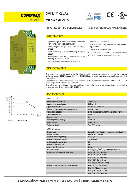
DATA SHEET SAFETY RELAYYRB-4EML-31SFOR SAFETY LIGHT CURTAINS/BARRIERS TYPE 4 SAFETY PROTECTION DEVICETECHNICAL DATAAPPLICATION AREAThe safety relay can be used to monitor electrosensitive protective equipment with monitored active switching output (OSSD) in accordance with EN 61496 as well as emergency stop and safety door locking mechanisms.Depending on the external wiring, up to category 4, PL e according to EN ISO 13849-1 or SILCL 3 according to EN 62061 can be achieved.The safety relay is equipped with three enabling current paths that drop out without delay corresponding to stop category 0 according to EN 60204-1.–For safety light curtains and access control bar-riers, emergency stop, door switch–Safety Integrity Level (SIL) 3 according to IEC/EN61508–Claimed Level (SIL CL) 3 according to IEC/EN62061–Performance Level (PL) e and category 4 ac-cording to EN/ISO 13849-1–Safety category 4 according to EN 954-1–Certified TÜV, CE and UL–Output: 3 N.O. safety contacts / 1 N.C. monitor-ing contact–Manual or automatic restart–LED indicator for channel 1, 2 and power supply–22.5 mm wide, DIN-rail-mountable housingMAIN FEATURESFigure 1 Derating curveTECHNICAL DATADATA SHEETYRB-4EML-S41_E.indd / page 1-2 / rev. 1 / 27.01.16 / MDMDATA SHEETPART REFERENCESTRUCTURE AND OPERATION (BLOCK DIAGRAM)WARNING: Risk of electric shockDuring operation, parts of electrical switching devices carry hazardous voltages.Before working on the switching device, disconnect the power.Please observe the safety regulations of electrical engineering and industrial safety and liability associations!Disregarding these safety regulations may result in death, serious personal injury or damage to equipment.Startup, mounting, modifications, and upgrades should only be carried out by a skilled electrical engineer!WARNING: Risk of automatic machine restart!For emergency stop applications, the machine must be prevented from restarting automatically by a higher-level controlsystem.Protective covers must not be removed when operating electrical switching devices.WARNING: Danger due to faulty devices!The devices may be damaged following an error and correct operation can no longer be ensured.In the event of an error, replace the device immediately.Repairs to the device, especially if the housing must be opened, may only be carried out by the manufacturer or autho-rized persons. Otherwise the warranty is invalidated.NOTE: Risk of damage to equipment due to incorrect installation!For reliable operation, the safety relay must be installed in housing protected from dust and humidity (IP 54).Carry out wiring according to the application. Refer to the “Application examples” section for this.NOTE: Risk of damage to equipment due to noise emissionsWhen operating relay modules the operator must meet the requirements for noise emission for electrical and electronic equipment (EN 61000-6-4) on the contact side and, if required, take appropriate measures.For the diagnostic description, please refer to the application manual for PSR safety relays.SAFETY NOTESFigure 2 Block diagramDATA SHEETKEYTwo-channel light grid monitoring (cross-circuit detection via light grid)– Manual activation– Automatic activation with jumper at S33-S35– Suitable up to category 4, PL e (EN ISO 13849-1), SILCL 3 (EN 62061)APPLICATION EXAMPLEFigure 4 Two-channel light grid monitoringOPERATING AND INDICATION ELEMENTSFigure 3 YRB-4EML-31SYRB-4EML-31SYRB-4EML-S41_E.indd / page 3-4 / rev. 0 / 19.11.15 / MDMDATA SHEETAPPLICATION EXAMPLETwo-channel emergency stop circuit without cross-circuit detection, with monitored reset button– Manual activation– Automatic activation with jumper at S33-S35– Suitable up to category 3, PL d (EN ISO 13849-1), SILCL 2 (EN 62061)Single-channel emergency stop monitoring– Manual activation– Automatic activation with jumper at S33-S35– Suitable up to category 1, PL c (EN ISO 13849-1), SILCL 1 (EN 62061)Two-channel safety door monitoring without cross-circuit detection, with monitored reset button– Manual activation– Automatic activation with jumper at S33-S35– Suitable up to category 3, PL d (EN ISO 13849-1), SILCL 2 (EN 62061)Figure 5 Two-channel emergency stop circuit without cross-circuit detectionFigure 6 Single-channel emergency stop circuit with monitored reset buttonFigure 7 Two-channel safety door monitoring without cross-circuit detectionYRB-4EML-31SYRB-4EML-31SYRB-4EML-31SYRB-4EML-S41_E.indd / page 5 / rev. 0 / 19.11.15 / MDM。
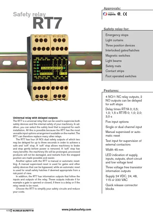
RT7Safety relayUniversal relay with delayed outputsThe RT7 is a universal relay that can be used to supervise bothsafety devices and the internal safety of your machinery. In ad-dition, you can select the safety level that is required for eachinstallation. All this is possible because the RT7 has the mostversatile input options arrangement available on the market. TheRT7 can therefore replace many other relays.The RT7 has four (4 NO) dual safety outputs of which twomay be delayed for up to three seconds in order to achieve asafe and ‘soft’ stop. A ‘soft’ stop allows machinery to brakeand stop gently before power is removed. A ‘soft’ stop hasmany benefi ts: the machinery life will be prolonged, processedproducts will not be damaged, and restarts from the stoppedposition are made possible and easier.Another option with the RT7 is manual or automatic reset-ting. A manual supervised reset is used for gates and othersafety devices that can be bypassed, while an automatic resetis used for small safety hatches if deemed appropriate from arisk point of view.In addition, the RT7 has information outputs that follow theinputs and outputs of the relay. These outputs indicate if forexample a gate is opened or closed, if there is a delay or if therelay needs to be reset.Choose the RT7 to simplify your safety circuits and reduceyour costs.Safety relay for:Emergency stopsLight curtainsThree position devicesInterlocked gates/hatchesMagnetic switchesLight beamsFeatures:4 NO/1 NC relay outputs, 2NO outputs can be delayedfor soft stopsDelay times RT7A 0; 0,5;1,0; 1,5 s RT7B 0; 1,0; 2,0;3,0 sFive input optionsSingle or dual channel inputManual supervised or auto-matic resetTest input for supervision ofexternal contactorsWidth 45 mmLED indication of supply,inputs, outputs, short-circuitand low voltage levelThree voltage free transistorinformation outputsSupply 24 VDC, 24, 48,115 or 230 VACQuick release connectorblocks123456789101112Technical information - RT7 A/BInputsThe RT7 can be confi gured to operate in either of the following input options:1. Single channel, 1 NO contact from +24 VDC, safety cat. 1.2. Dual channel, 2 NO contacts from +24 VDC, safety cat.3.3. Dual channel, 1 NO, 1 NC contact from +24 VDC, safety cat.4.4. Dual channel, 1 NO contact from 0V and 1 NO contact from +24 VDC, safety cat. 4.5. Safety mats/contact strips, 1 ‘contact’ from 0V and 1 ‘contact’ from +24 VDC, safety cat. 1.When the input/inputs are activated and the test/supervised reset is complete, relays 1,2,3 and 4 are activated. Relays 1 and 2 are immediately de-energized when the inputs are deactivated in ac-cordance with the input option selected. Relays 3 and 4 are either de-energized immediately or after the selected time delay.All the relays (1,2,3 and 4) must be de-energized before the RT7 can be reset.Transistor output status informationThe RT7 has three(3) voltage free transistor outputs that can be connected to a PLC, computer or other monitoring device. These outputs give the input and output status of the relay.Reset and testingThe RT7 has two reset options; manual and automatic.The manual supervised reset is utilised when the RT7 is used to monitor safety devices that can be bypassed, i.e. to ensure that the outputs of the safety relay do not close just because the gate is closed.The automatic reset should only be used if acceptable from a risk point of view. The RT7 can also test (supervise), if for example, contactors and valves etc are de-energized/de-activated before a restart is allowed.Indication of low voltage The ‘On’ LED will fl ash if the relay voltage falls below an accept-able level. This indication will also be given if a monitored safety mat/contact strip is actuated. See connection option 5.Safety levelThe RT7 has internal dual and supervised safety functions. Power failure, an internal faulty component or external interference will not present a risk to options with the highest safety level. A manual reset requires that the reset input is closed and opened before the safety relay outputs are activated. A short-circuit or a faulty reset button is consequently supervised.When the RT7 is confi gured for dual channel input, both the inputs are supervised for correct sequence operation before the unit can be reset. The input options 3 and 4 have the highest safety levels as all short-circuits and power failures are supervised. This in combination with internal current limitation makes the relay ideal for supervision of safety mats and contact strips.Regulations and standardsThe RT7 is designed and approved in accordance with appropri-ate directives and standards. Examples of such are 98/37/EC, EN ISO 12100-1/-2, EN 60204-1, EN 954-1/EN ISO 13849-1.**Only for AC supplyThe RT7 DC option should be supplied with +24 V on A1 and 0 V on A2.The RT7 AC option should be supplied with the appropriate supply voltage via connections A1 and A2.The S23/ must be connected to protective earthNOTEWith both DC and AC modules, if cable shielding is used this must be connected to an earth rail or an equivalent earth point.Connection examplesDC-supply of AC-unitsAll AC-units can also be supplied by +24 VDC to S53 (0VDC to S23).DC supplyAC supply*1. SINGLE CHANNEL, 1 NO from +24VThe input (contact to S14) must be closedbefore the outputs can be activated. When the input contact is opened the relay safety output contacts open.2. DUAL CHANNEL, 2 NO from +24VBoth input contacts (S14 and S34) must be closed before the relay outputs can be activated. The safety relay contacts will open if one or both of the input contacts are opened. Both the input contacts must be opened before the relay can be reset. A short-circuitbetween the inputs S14 and S34 can only be supervised if the device connected to the inputs has short-circuit supervised outputs, e.g. JOKAB Focus light curtains.3. DUAL CHANNEL, 1 NO, 1 NC from +24V One input contact must be closed (S14) and one opened (S44) before the relay outputs can be activated. The safety relay contacts will open if one or both of the inputs change state or in the case of a short-circuit between S14 and S44. Both inputs must be returned to their initial positions before the relay out-puts can be reactivated.4. DUAL CHANNEL, 1 NO from +24V,1 NO from 0V Relay functions as option 2, but a short-circuit, in this case between inputs S14 andS24, is supervised (safety outputs areopened). 5. Safety mat/Contact stripBoth ‘contact’ inputs from an inactivatedsafety mat/contact strip, must be made in order to allow the RT7 relay outputs to be activated. When the safety mat/contact strip is activated or a short-circuit is detected across S14-S23, the relay will de-energize (safety outputs open) and the ‘ON’ LED will flash. As output S13 has an internal current limit of 70 mA, the RT7 will not be overloaded when the mat/contact strip is activated or a short circuit is detected.Manual supervised resetTime delays are selected by linking the appropriate T0, T1 and T2 connections.When a stop signal is detected a program stop command is first given to the PLC/servo which brakes the dangerous machine opera-tions in a ‘soft’ and controlled way.The delayed relay safety outputs will then turn off the power to the motors, i.e. when the machinery has already stopped. It takes usually around 0.5 to 3 seconds for a danger-ous action to be stopped softly.The manual supervised reset contact con-nected to input X1 must be closed and opened in order to activate the relay out-puts.Automatic reset*connected to S13 for safety mat/contact stripThe RT7 has four (4 NO) safety outputs of which two can be delayed, and 1 NC information output.In order to protect the RT7 output contacts it is recommended that loads (inductive) are suppressed by fitting correctly chosen VDR’s, diodes etc. Diodes are the best arc suppressors, but will increase the switch off time of the load. Transistor outputsThe RT7 has three(3) voltage free transistor information outputs.The transistor outputs are supplied with voltage to Y13 either from S53 (+24V) or externally from 5 to 30 VDC. Y14, Y24 and Y34 follow the inputs and outputs as follows:• Y14 becomes conductive when the re- lay input conditions are fulfilled.• Y24 becomes conductive when both the output relays are activated.• Y34 becomes conductive when both the delay output relays are activated.***NOTEThese outputs are only for information purposes and must not be connected to the safety circuits of the machinery.Connection of safety devices - RT7 A/BReset connections - RT7 A/BAutomatic reset is selected when S53, X1 and X4 are linked. The relay outputs are then activated at the same time as the inputs.Testing external contactor statusContactors, relays and valves can besupervised by connecting ‘test’ contacts between S 53 a nd X 1. B oth m anual s upervised and automatic reset can be used.Output connections - RT7 A/BRelay outputsTime delay outputs123456789101112Technical data – RT7 A/BManufacturerJOKAB SAFETY AB, SwedenArticle number/Ordering dataRT7BRT7A10-028-10 24DC 3 s 10-028-12 24AC 3 s 10-028-13 48AC 3 s 10-028-14 115AC 3 s 10-028-15 230AC 3 s 10-028-20 24DC 1,5 s 10-028-22 24AC 1,5 s 10-028-23 48AC 1,5 s 10-028-24 115AC 1,5 s 10-028-25 230AC 1,5 s Colour Black and beigeWeight 405 g (24 VDC) 550 g ( 24-230 VAC)SupplyVoltage (A1-A2)24 VDC +15/-20%,24/48/115/230 VAC, +/-15%, 50-60 Hz Power consumptionDC supply, nominal voltage AC supply, nominal voltage4.6 W 8.7 WConnection S13Short-circuit protected voltage output,70 mA +/-10% current limitation.Is used for the inputs S14, S34 and S44.Connection S53Short-circuit protected voltage output,internal automatic fuse, max 270 mA.Is used for the reset and autoreset inputs X1 and X4.Connection S230V connection for input S24.Safety inputs S14 (+) input S24 (0V) input S34 (+) input S44 (+) input 20mA 20 mA 20 mA 25 mAReset input X1 Supply for reset input Reset current Minimum contact closure time for reset +24 VDC600 mA current pulse at contact closure, then 30 mA.100msMaximum external connec-tion cable resistance at nominal voltage for S14, S24, S34 S44, X1300 Ohm 150 Ohm Response time At Power on DC/ACWhen activating (input-output)When deactivating (input-output)At Power loss <90/<140 ms <20 ms <20 ms <80 msDelay time options RT7A RT7B0; 0.5; 1.0; 1.5 secs 0; 1.0; 2.0; 3.0 secsRelay outputsNO direct (relays 1/2)NO direct or delayed (relays 3/4)NC (relays 1/2)Maximum switching capacity res. load Relays 1/2 A CDCRelays 1/2 total Relays 3/4 A CDCRelays 3/4 totalMinimum load (Relays 1/2/3/4) Contact material Mechanical life 2216A/250 VAC/1500 VA 6A/24 VDC/150 W9A distributed on all contacts 6A/250 VAC/1380 VA 6A/24 VDC/138 W6A distributed on all contacts 10 mA/10V (if load on contact has not exceeded 100 mA)AgSnO 2+ Au flash >107 operationsTransistor outputs External supply to Y13Y14Y24Y34Maximum load of Y14,Y24, Y34Maximum voltage drop at maximum load +5 to +30 VDCIndicates that the input condi-tions are fulfilledIndicates that the output relays 1/2 are activatedIndicates that the delay output relays 3/4 are activated 15 mA /output 2.4 VLED indicationOnIn1 In2 1 2tSupply voltage OK, the LED is on.Flashing light in case of under-voltage or overload.Indicates that the input conditionsare fulfilled.Indicates that the output relays1/2 are activated.Indicates that the delay output relays 3/4 are activated.Mounting RailOperating temperature range 24VDC 24-230VAC35 mm DIN rail -10° C to + 55° C -10° C to + 45° CConnection blocks (detachable)Maximum screw torque Maximum connection area Solid conductorsConductor with socket contact Air and creep distance 1 Nm1x4mm 2 /2x1.5mm 2 /12AWG 1x2.5mm 2 /2x1mm 24kV/2 IEC 60664-1Protection class EnclosureConnection blockIP 40 IEC 60529IP 20 IEC 60529Connector blocks are detachable (without cables having to be disconnected)。
• Safety relay that monitors up to 63 Safety Input Modules• Safety output available on 2 separate relay outputs (NO)• Safety approved according to IEC/EN 61508-SIL3, IEC/EN 62061-SIL3 and ISO/EN 13849-1 PL e• Approval authority: TÜV Rheinland Group • cULus approved• Automatic or manual restart• Status output for external equipment (e.g. PLC)• Operates on a standard Dupline ® network• It is possible to use DuplineSafe modules and standard Dupline ® modules on the same bus • H8-housing• For mounting on DIN-rail (EN 50022)• LED-indication for supply, relay status, manual restart ready and Dupline ® carrier • AC power supply• Configuration with GS73800080Product DescriptionDuplineSafe relay output module approved according to IEC/EN 61508-SIL3, IEC/EN 62061-SIL3 and ISO/EN 13849-1 PL e by TÜV. The module monitors up to 63 DuplineSafe input modules, type number G S751021xx. The NO relay contacts are only in the closed position if a valid “safe state” signal is received from all the Safety Input modules being mon-itored. The module can be configured to operate with automatic or manual restart after the safety relays have been released. A non-safe status output is available for connection to external equipment, e.g. a PLC. The Module must be configured prior to installation by means of the DuplineSafe configur-ation unit GS73800080. Type SelectionSupply Ordering no.DuplineSafe Safety Input Module230 VACGS 3830 0143 230DuplineSafeSafety Relay Output ModuleType GS 3830 0143Safety SpecificationsStandards SFF97% PFD (T1 = 1 year)5.5 x 10⁻⁶ PFH9.3 x 10-9/hOutput SpecificationsNote: The GS38300143 must be de-energized (power off) before programming til moduleGeneral SpecificationsSupply SpecificationsPower Supply 230 VAC +/- 15%115 VAC +/- 15% Frequency45 to 65 Hz Power consumption 4 VA Power dissipation3 WWiring DiagramMode of OperationThe Safety Output module G S3******* monitors up to 63 Safety Input modules, type number G S751021xx. Each Safety Input module is monitoring the status of one potential-free contactin a safety device, e.g. anemergency stop palm but-ton or pull cord switch. The Safety Input modules arecontinuously transmitting on the Dupline ® bus the status of the safety contacts using a dynamic signaling princi-ple on two Dupline ® channel addresses (please refer to G S751021xx datasheet for more details). During configuration of theSafety Output module, theuser must define on whichDupline ® channel address-es Safety Input modules shall be monitored. If all themodules are sending avalid “safe-state” signal,then the relay contacts ofthe Safety Output modulewill be closed. In any other situation (non-safe signal received from one or moreSafety Input modules or bus fault), the relay contacts willbe open, thus keeping the system in a safe state. Find below a principle diagram of a DuplineSafe system.The Channel Generator Any type of Dupline ® Chan-nel G enerator can be used, as this component is not part of the safety function. However, it is important to note that all Dupline ® chan-nel addresses used for Safe-ty Input modules must be monostable. Split I/O mode and intelligent channel func-tions are not allowed. If this rule is not obeyed, the relay contacts of the Safety Out-put module will remain in the open position in any situa-tion.Combined SystemsIt is allowed to use stan-dard Dupline ® modules on the channel addresses not used for safety signals, thus allowing combined systems.Monitoring from a PLC, PC or Text DisplayThere are two products available for interfacing a DuplineSafe system to a PLC, PC, Text Display or Touchscreen. One possi-bility is the Profibus-DP gateway (G S3*******), the other possibility is the small Modbus inter-face G STI50 for Text dis-plays and Touchscreens. Using these products, it is possible to monitor theIndicatorsSupply OK Dupline ® OK Relay statusManual restart ready Configuration modeGS 3830 0143DuplineSafe Principle Diagram Input SpecificationsGS 3830 0143Mode of Operation (cont.)status of all the inputs of the Safety Input modules from e.g. a PLC or Text Display. It is not allowed to perform any control function on the channel addresses used for safety signals.Automatic or manual restart Two different operation modes for restart can be configured. A restart is needed whenever the Safety output has been brought to the safe state (relay con-tacts open). If “automatic restart” is selected then the Safety Output module will automatically close the relay contacts as soon as a valid “safe-state” signal is received from all the Safe-ty Input modules. If “manu-al restart” is selected, an activation of the “manu-al restart” input is required to make a restart, and the restart will only happen ifall Safety Input modules aresending a “safe-state” signal.Status outputThe status output is ONwhen a fault or a safetytransmitter is actuated. Thisoutput can be used as anindication by using a LEDor buzzer/horn to sound analarm.Synchronization ChannelThe synchronization channelis used by the Safety Relayto send out a synchroniz-ation signal to the SafetyInput modules on the bus.Therefore, all the SafetyInput modules and the Safe-ty Relay, which together areperforming a safety function,must be coded for the samesynchronization channel.But in case there is alreadyanother safety output mod-ule on the bus sending asynchronization signal onthis channel, then this signalcan be used by other safetyoutput modules.Configuration of the SafetyOutput modulePrior to installation, theSafety Output module needsto be configured by theDuplineSafe configurationunit G S7*******. The fol-lowing parameters need tobe selected:Number of channels on theDupline® busThe “number of channels”is actually selected on thechannel generator, but theRelay Output Module needto know this figure to ensurecorrect operation.Channel addresses of SafetyInput modules to be mon-itoredEach Safety Input Module isusing two channel address-es to send its signal. Thepossible selections are inthe range A3/A4 .. P7/P8.It must be defined whichchannel addresses the Safe-ty Output module shall mon-itor. (Please note that thechannel address A1/A2 isnot allowed in the system).Synchronization channelPlease refer to abovedescriptionPlease refer to the usermanual for the Dup-lineSafe Configuration UnitG S7******* for detailedinstructions on how to con-figure the Safety Outputmodule GS38300143 to per-form the desired function.DuplineSafe - System Characteristics and RulesReaction timeThe reaction time for the total Dupline® safety-loop depends of the num-ber of Dupline® channels. The response time can be calculated as:Reaction time on r elay r elease (wo r st-case): 2 x Number of Dupline® chan-nels + 40 [ms]Note: Reaction time is for the total Dupline® safe-ty-loop; from a safety input goes to non-safe state until the output relay is released. Reaction time on r elay acti-vate (wor st-case): 4 x Num-ber of Dupline® channels + 80 [ms]Note: Reaction time is for the total Dupline® safe-ty-loop; from a safety input goes to safe state until the output relay is activatedTopologyThe Dupline® system has free topology, so cable branches can freely be made at any point in the system. There are no specif-ic length restriction on cablebranches.Cable typesA non-shielded twisted paircable with a cross-sec-tion of 1.5 mm2 is recom-mended, but the Dup-line® bus can also run oncable without twistingand with lower cross-sections. However, the rulesmentioned below must beobeyed.Cabling rulesThe Dupline® system is anextremely robust transmis-sion system, but the followingrules should be obeyed:Rule no. 1The two Dupline® wires mustbe “floating” (none of thetwo wires may be connect-ed to any other potential).Specifically it should bemade sure that the Dupline®common is not connect-ed to protective earth, e.g.through the power supply.Rule no. 2If the longest cable pathexceeds 1.5 km a DT01 ter-mination unit needs to beinstalled at the point farthestaway from the channel gen-erator.If above rules are notobeyed, noise may beinduced in the system, andas a result the relay contactsof the safety output mod-ule will remain in the openposition.Distance, cable and num-ber of Safety input modulesIt is not always the full cap-acity of 63 Safety Inputmodules can be utilized. Itdepends on the cable typeand the length of the cable.The following rule applies:Total current x cable loopresistance < 3,7 VThe total current is the sum-marized current consump-tion of all Dupline®-poweredmodules on the bus. A SafetyInput module typ. uses 1mA.Cable loop esistance = 2x Length of cable (km) xresistance/km (for the cabletype used)Please note that the “lengthof cable” in this calculationis not necessarily the totallength of cable used, it is thecable path from the chan-nel generator to the farthestSafety Input module. In otherwords, only the longestcable path counts.If the above rule is notobeyed, the relay contactsof the Safety Output mod-ule will remain open in anysituation.Example: How many safe-ty Input modules can beinstalled on a 3 km of 1.5mm2 cable ?Cable loop resistance = 2 x3 km x 13,6 Ω/km = 81,6 ΩMax total current = 3,7 V /81,6 Ω = 45,3 mA.Conclusion: In this systemthe max capacity is 45 Safe-ty Input modules, since eachinput module uses 1 mA.DuplineSafe Safety ProcedureIn order to ensure correct safety function of a Dup-line®Safe system, the steps below need to be carried out:1.Identify the exact numberof Safety Input modulesrequired2.Make a table defining thechannel address of each Safety Input module (addresses to be selectedin the range A3/A4 ..P7/ P8)3. Physically allocate thenumber of Safety Inputmodules required andprogram them one by oneaccording to the addresstable, using the Dupline®-Safe Configuration unitGS73800080.4. Configure carefully theSafety Output module tomonitor exactly thechannel addressesselected for the Dupline®Input modules5. Connect all the SafetyInput modules and theSafety Output module tot h e D u p-line® two-wire busand bring all the inputs tothe safe state.6. Now the Safety RelayOutput should haveclosed the contacts. Ifthis is not the case,please review if theaddressing of the safetyinput modules and theconfiguration of the safe-ty output module complieswith each other. If thisdoes not solve theproblem, please checkthat all the DuplineSaferules have been obeyed.7. Now checkeach individualSafety Input module by:a.Remove the busconnection from SafetyInput module and checkthat the safety relayoutput releases.b. Re-connect the safetyinput module to the busand open the inputcontacts. Check that thesafety relay outputreleasesWhen all safety inputmodules have been checkedthis way, the DuplineSafesystem is ready to operate.GS 3830 0143。
Eaton 118701Eaton ESR5 Safety relay emergency stop/protective door, 24VDC/AC, 4 enabling pathsEspecificaciones generalesEaton ESR5 Safety relay 1187014015081168415114.5 mm 99 mm 22.5 mm 0.218 kgUL Category Control No.: NKCR; NKCR7Certified by UL for use in Canada CSA-C22.2 No. 14-95 IEC 62061 ULCSA Class No.: 3211-83; 3211-03 UL File No.: E29184 IEC 61508, Parts 1-7 EN ISO 13849-1 EN 50178 2014/30/EU IEC/EN 60204 CE UL 508UL report applies to both US and CanadaMachines 2006/42/EGESR5-NO-41-24VAC-DCProduct NameCatalog Number EANProduct Length/Depth Product Height Product Width Product Weight CertificationsModel CodeScrew connection4 Non-delayed enable current pathsAutomatic startReinforced insulation6 kV between input circuit / NC contacts, and enable current pathsManual startSafe insulationBasic insulationFeedback circuitApproval for TÜVDetachable clampsStart inputApproval according to UL1-channelEnclosure: Polyamide (PA), not reinforcedContacts: silver tin oxide, gold plated (AgSnO2, 0.2 µ m Au)M3 screw terminals140 mA, AC65 mA, DCIP20Installation location: ≥ IP54Terminals: IP20Enclosure: IP20100 %According to EN 61000-6-4According to EN 61000-6-2Status indication of SmartWire-DT network: Green LED 10,000,000 OperationsBasic deviceRail mounting possibleTop-hat rail fixing (according to IEC/EN 60715, 35 mm) 22.5 mmIII2Normally 5.16 WElectronic safety relaysElectric connection type FeaturesFitted with:FunctionsMaterial Connection type Current consumption Degree of protection Duty factorEmitted interference Interference immunity LED indicator Lifespan, mechanical ModelMounting method Mounting width Overvoltage category Pollution degree Power lossProduct category ProtectionFinger and back-of-hand proof, Protection against direct contact when actuated from front (EN 50274)4000 V AC1000 msLevel cSIL 1, Safety integrity level, In accordance with IEC 61508 SILCL 1, Safety integrity level claim limitCat. 1, Category4.05 x 10-10, PFHd, Probability of failure per hourModule used to safely interrupt electrical circuitsMonitoring of position switchesMonitoring of emergency-stop circuitsSafety relay for monitoring emergency stop and protective door switchMax. 0.5 Hz, Input dataAC/DC As required240 Months (High Demand)167 Months (Low Demand)3 A at 3600 O/h, AC-15 at 230 V, Outputs0.4 W4 A at 360 O/h, AC-15 at 230 V, OutputsIn accordance with IEC 60947-5-1, Outputs4 A at 360 O/h, DC-13 at 24 V, Outputs2.5 A at 3600 O/h, DC-13 at 24 V, Outputs10 - 150 Hz, Amplitude: 0.15 mm, Acceleration: 2 g, (IEC/EN 60068-2-6)795 - 1080 hPa (operation)Max. 2000 m-20 °C55 °C-40 °C70 °CDry heat to IEC 60068-2-2Damp heat, constant, to IEC 60068-2-3Clearance in air and creepage distances according to EN 50178, UL 508, CSA C22.2, No. 14-95Condensation: Non-condensingRated impulse withstand voltage (Uimp) Recovery timeSafety performance level (EN ISO 13849-1) Safety parameter (IEC 62061)Stop category (IEC 60204)Suitable forSwitching frequencyTypeVoltage type Mounting positionProoftestSwitching capacityVibration resistanceAir pressureAltitudeAmbient operating temperature - min Ambient operating temperature - max Ambient storage temperature - min Ambient storage temperature - max Climatic proofingEnvironmental conditionsOperating temperature - minEmergency stop category 0; emergency switching off Feedback circuitProtective door-20 °C 55 °C< 75 %2 x (0.2 – 1) mm², solid1 x (0.25 – 2.5) mm², flexible with ferrule2 x (0.25 – 1) mm², flexible with ferrule 24 - 12 AWG, solid or stranded1 x (0.2 – 2.5) mm², solid7 mm0.6 x 3.5 mm, Terminal screws2, Terminal screw, Pozidriv screwdriver 0.6 Nm, Screw terminals0.025 - 6 A1.6 W (DC operated)3.4 W (AC operated 50/60 Hz) 0 V26.4 V20.4 V24 V0 V24 V250 V24 V AC/DC (power supply) 1500 VA, max., resistive load (τ = 0 ms), at 250 V AC 42 W max., inductive load (τ = 40 ms), at 24 V DC 88 W max., resistive load (τ = 0 ms), at 220 V DC 288 W max., resistive load (τ = 0 ms), at 48 V DC 144 W max., resistive load (τ = 0 ms), at 24 V DC42 W max., inductive load (τ = 40 ms), at 220 V DC 42 W max., inductive load (τ = 40 ms), at 48 V DC 110 W max., resistive load (τ = 0 ms), at 110 V DC 42 W max., inductive load (τ = 40 ms), at 110 V DC∞ ms, Simultaneity for inputs 1/265 AOne- and two-channel4Operating temperature - maxRelative humidityTerminal capacityStripping length (main cable)Screwdriver sizeTightening torqueInrush currentPower supply circuitRated control supply voltage (Us) at AC, 50 Hz - min Rated control supply voltage (Us) at AC, 50 Hz - max Rated control supply voltage (Us) at AC, 60 Hz - min Rated control supply voltage (Us) at AC, 60 Hz - max Rated control supply voltage (Us) at DC - minRated control supply voltage (Us) at DC - max Rated insulation voltage (Ui)Rated operational voltage Breaking powerInputNominal currentNumber of inputsNumber of outputs (safety related, delayed) with contact Number of outputs (safety related, undelayed) with contact Number of outputs (signaling function, delayed) with contact230 V ACApprox. 24 V DC at input, starting and feedback circuit2.3 A, Input dataShort-circuit proof, 24 V, Fuse for control circuit supply, Control circuitMiniature circuit-breaker with characteristic C: 24 V AC/DC 6 A, For output circuits, ExternalFuse 6 A gL/gG, For output circuits, External6 A, Output fuse, Output data 122 Ω (input and starting circuits for UN)65 ms typ. (K1, K2 - for UN automatic mode) 20 ms typ.72 A² (ITH² = I1² + I2² + I3² + I4²)45 ms22 Ω (impedance)250 V6 A N/O, Limiting continuous current3 A N/C, Limiting continuous current0 W0 W0 W0 A5.16 WMeets the product standard's requirements. Meets the product standard's requirements. Meets the product standard's requirements.eaton-safety-relays-esr5-safety-relay-characteristic-curve-009.eps eaton-safety-relays-esr5-safety-relay-characteristic-curve-008.epseaton-safety-relays-relay-esr5-safety-relay-dimensions-002.eps eaton-safety-relays-relay-esr5-safety-relay-3d-drawing.eps eaton-general-esr5-safety-relay-symbol.epseaton-general-technology-esr5-safety-relay-symbol.epsDA-CE-ETN.ESR5-NO-41-24VAC-DCeaton-safety-relays-esr5-safety-relay-wiring-diagram-005.eps eaton-safety-relays-esr5-safety-relay-wiring-diagram-004.eps eaton-safety-relays-esr5-safety-relay-wiring-diagram-006.epsDA-DC-00004584.pdfDA-DC-00004576.pdfShort-circuit currentShort-circuit protection Short-circuit protection rating Number of outputs (signaling function, undelayed) with contact Permissible total cable resistancePick-up timeQuadratic summation currentReset timeResistanceSwitching voltageUninterrupted currentEquipment heat dissipation, current-dependent PvidHeat dissipation capacity PdissHeat dissipation per pole, current-dependent PvidRated operational current for specified heat dissipation (In) Static heat dissipation, non-current-dependent Pvs10.2.2 Corrosion resistance10.2.3.1 Verification of thermal stability of enclosures10.2.3.2 Verification of resistance of insulating materials to normal heat Characteristic curve DibujoseCAD model Esquemas eléctricosInformes de certificaciónMeets the product standard's requirements.Meets the product standard's requirements.Does not apply, since the entire switchgear needs to be evaluated.Does not apply, since the entire switchgear needs to be evaluated.Meets the product standard's requirements.Does not apply, since the entire switchgear needs to be evaluated.Meets the product standard's requirements.Does not apply, since the entire switchgear needs to be evaluated.Does not apply, since the entire switchgear needs to be evaluated.Is the panel builder's responsibility.Is the panel builder's responsibility.Is the panel builder's responsibility.Is the panel builder's responsibility.Is the panel builder's responsibility.The panel builder is responsible for the temperature rise calculation. Eaton will provide heat dissipation data for the devices.IL05013028ZDA-CS-esr5_no41_nz21 DA-CD-esr5_no41_nz2110.2.3.3 Resist. of insul. mat. to abnormal heat/fire by internal elect. effects10.2.4 Resistance to ultra-violet (UV) radiation10.2.5 Lifting10.2.6 Mechanical impact10.2.7 Inscriptions10.3 Degree of protection of assemblies10.4 Clearances and creepage distances10.5 Protection against electric shock10.6 Incorporation of switching devices and components10.7 Internal electrical circuits and connections10.8 Connections for external conductors10.9.2 Power-frequency electric strength10.9.3 Impulse withstand voltage10.9.4 Testing of enclosures made of insulating material10.10 Temperature rise10.11 Short-circuit rating Instrucciones de montaje mCAD modelEaton Corporation plc Eaton House30 Pembroke Road Dublin 4, Ireland © 2023 Eaton. All Rights Reserved. Eaton is a registered trademark.All other trademarks areproperty of their respectiveowners./socialmediaIs the panel builder's responsibility. The specifications for the switchgear must be observed.Is the panel builder's responsibility. The specifications for the switchgear must be observed.The device meets the requirements, provided the information in the instruction leaflet (IL) is observed.10.12 Electromagnetic compatibility10.13 Mechanical function。
Safety relaysThis document is the original document.All rights to this documentation are reserved by Pilz GmbH & Co. KG. Copies may be made for internal purposes. Suggestions and comments for improving this documentation will be gratefully received.Pilz®, PIT®, PMI®, PNOZ®, Primo®, PSEN®, PSS®, PVIS®, SafetyBUS p®, SafetyEYE®, SafetyNET p®, the spirit of safety® are registered and protected trademarks of Pilz GmbH & Co. KG in some countries.SD means Secure DigitalPNOZ s2 safety relayThe safety relay provides a safety-related interruption of a safety circuit.The safety relay meets the requirements of EN 60947-5-1, EN 60204-1 and VDE 0113-1 and may be used in applications with}E-STOP pushbuttons}Safety gatesFor your safety}Only install and commission the unit if you have read and understood these operating instructions and are familiar with the applicable regulations for health and safety at work and accident prevention.Ensure VDE and local regulations are met, especially those relating to safety.}Any guarantee is rendered invalid if the housing is opened or unauthorised modifica-tions are carried out.Unit features}Positive-guided relay outputs:– 3 safety contacts (N/O), instantaneous– 1 auxiliary contact (N/C), instantaneous}Safe separation of safety contacts from all other circuits} 1 semiconductor output}Connection options for:– E-STOP pushbutton– Safety gate limit switch– Start button} A connector can be used to connect 1 PNOZsigma contact expansion module}Operating modes can be set via rotary switch}LED indicator for:– Supply voltage– Input status, channel 1– Input status, channel 2– Switch status of the safety contacts– Start circuit– Errors}Plug-in connection terminals (either spring-loaded terminal or screw terminal)Safety featuresThe relay meets the following safety requirements:} The circuit is redundant with built-in self-monitoring.} The safety function remains effective in the case of a component failure.} The correct opening and closing of the safety function relays is tested automatically ineach on-off cycle.} The unit has an electronic fuse.*Safe separation in accordance with EN 60947-1, 6 kVFunction description} Single-channel operation: no redundancy in the input circuit, earth faults in the resetand input circuit are detected.}} Manual start: Unit is active once the input circuit is closed and then the start circuit isclosed.}Monitored start with falling edge: Unit is active once– the input circuit is closed and then the start circuit is closed and opened again.– the start circuit is closed and then opened again once the input circuit is closed.}Monitored start with rising edge: Unit is active once the input circuit is closed and once the start circuit is closed after the waiting period has elapsed (see technical de-tails).} Increase in the number of available instantaneous safety contacts by connecting con-tact expander modules or external contactors/relays;A connector can be used to connect 1 PNOZsigma contact expander module.InstallationInstall base unit without contact expansion module:}Ensure that the plug terminator is inserted at the side of the unit.Connect base unit and PNOZsigma contact expansion module:}Remove the plug terminator at the side of the base unit and at the contact expansion module.}Connect the base unit and the contact expansion module to the supplied connector be-fore mounting the units to the DIN rail.Installation in control cabinet}The safety relay should be installed in a control cabinet with a protection type of at least IP54.}Use the notch on the rear of the unit to attach it to a DIN rail (35 mm).}When installed vertically: Secure the unit by using a fixing element (e.g. retaining brack-et or end angle).}Push the device upwards or downwards before lifting it from the DIN rail.WiringPlease note:}Information given in the "Technical details" must be followed.}Outputs 13-14, 23-24, 33-34 are safety contacts; output 41-42 is an auxiliary contact(e.g. for display).}Auxiliary contact 41-42 and semiconductor output Y32 should not be used for safety circuits!}To prevent contact welding, a fuse should be connected before the output contacts (see technical details).}Calculation of the max. cable length l max in the input circuit:RlmaxR l / kmImax=R lmax = max. overall cable resistance (see technical details)R l / km = cable resistance/km}Use copper wire that can withstand 60/75 °C.}Sufficient fuse protection must be provided on all output contacts with capacitive and in-ductive loads.Preparing for operationOperating modesThe operating mode is set via the rotary switch on the unit. You can do this by opening the cover on the front of the unit.CAUTION!Do not adjust the rotary switch during operation, otherwise an error mes-sage will appear, the safety contacts will open and the unit will not be readyfor operation until the supply voltage has been switched off and then onagain.Set operating modes}Switch off supply voltage.}Select operating mode via the operating mode selector switch "mode".}If the operating mode selector switch "mode" is in its start position (vertical position), an error message will appear.Connection}Supply voltage}Input circuit}Start circuit/feedback loop}Semiconductor outputOperationThe unit is ready for operation when the Power LED is permanently lit.LEDs indicate the status and errors during operation:LED onLED flashesStatus indicatorsPower, In1, In2Input circuit is closed.OutSafety contacts are closed and semiconductor output Y32 carries a high signal.Reset24 V DC is present at S34.Error indicatorsFaultDiagnostics: Plug terminator not connected}Remedy: Insert plug terminator, switch supply voltage off and then on again.FaultDiagnostics: Internal error, unit defective}Remedy: Switch supply voltage off and then on again, change unit if neces-sary.PowerDiagnostics: Supply voltage too low}Remedy: Check the supply voltage.ResetFaultDiagnostics: Position of rotary switch is not permitted or rotary switch was ad-justed during operation.}Remedy: Switch supply voltage off and then on again.Power, In1, In2, Out, Reset, FaultDiagnostics: The operating mode selector switch "mode" is in its start position(vertical position)}Remedy: Switch off the supply voltage and set the required operating mode on operating mode selector switch "mode".Faults - malfunctions}Contact malfunctions: If the contacts have welded, reactivation will not be possible after the input circuit has opened.Service life graphThe service life graphs indicate the number of cycles from which failures due to wear must be expected. The wear is mainly caused by the electrical load; the mechanical load is negli-gible.Example}Inductive load: 0,2 A}Utilisation category: AC15}Contact service life: 2,000,000 cyclesProvided the application requires fewer than 2,000,000 cycles, the PFH value (see techni-cal details) can be used in the calculation.To increase the service life, sufficient spark suppression must be provided on all outputcontacts. With capacitive loads, any power surges that occur must be noted. With contac-tors, use freewheel diodes for spark suppression.Technical DetailsVoltage24 V24 VType DC DCVoltage tolerance-15 %/+10 %-15 %/+10 %Output of external power supply2,0 W2,0 W(DC)Residual ripple DC20 %20 %Continuous duty100 %100 %Max. inrush current impulseReset circuit0,50 A0,50 AFeedback loop0,50 A0,50 AMax. overall cable resistance Rl-maxSingle-channel at UB DC30 Ohm30 OhmVoltage atInput circuit DC24,0 V24,0 VReset circuit DC24,0 V24,0 VFeedback loop DC24,0 V24,0 VCurrent atInput circuit DC75,0 mA75,0 mAReset circuit DC7,0 mA7,0 mAFeedback loop7,0 mA7,0 mANumber of output contactsInstantaneous safety contacts33(N/O)Number11Number11Voltage24,0 V24,0 VMax. short circuit current IK 1 kA 1 kA Utilisation categoryIn accordance with the standard EN 60947-4-1EN 60947-4-1 Auxiliary contacts, AC1 at240 V240 VMin. current0,01 A0,01 AMax. current6,0 A6,0 AMax. power1500 VA1500 VA Auxiliary contacts, DC1 at24 V24 VMin. current0,01 A0,01 AMax. current6,0 A6,0 AMax. power150 W150 WSafety contacts, AC1 at240 V240 VMax. current6,0 A6,0 AMin. current0,01 A0,01 AMax. power1500 VA1500 VA Safety contacts, DC1 at24 V24 VMax. current6,0 A6,0 AMin. current0,01 A0,01 AMax. power150 W150 W Utilisation categoryIn accordance with the standard EN 60947-5-1EN 60947-5-1 Auxiliary contacts, AC15 at230 V230 VMax. current5,0 A5,0 AAuxiliary contacts, DC13 (6 cy-24 V24 Vcles/min) atMax. current5,0 A5,0 ASafety contacts, AC15 at230 V230 VMax. current5,0 A5,0 ASafety contacts, DC13 (6 cycles/24 V24 Vmin) atMax. current5,0 A5,0 A Contact fuse protection, externalsafety contactsIn accordance with the standard EN 60947-5-1EN 60947-5-1 Blow-out fuse, quick10 A10 ABlow-out fuse, slow 6 A 6 ACircuit breaker, 24V AC/DC,6 A 6 Acharacteristic B/CContact fuse protection, externalauxiliary contactsBlow-out fuse, quick10 A10 ABlow-out fuse, slow 6 A 6 ACircuit breaker, 24 V AC/DC,6 A 6 Acharacteristic B/C6,00 A6,00 A Conv. therm. current with 1 con-tactConv. therm. current with 2 con-6,00 A6,00 A tactsConv. therm. current with 3 con-5,00 A5,00 AWith automatic reset typ.75 ms75 ms With automatic reset max.250 ms250 ms With automatic reset after power75 ms75 mson typ.250 ms250 ms With automatic reset after poweron max.With manual reset typ.75 ms75 ms With manual reset max.250 ms250 ms75 ms75 msWith monitored reset with risingedge typ.250 ms250 ms With monitored reset with risingedge max.With monitored reset with falling55 ms55 msedge typ.70 ms70 msWith monitored reset with fallingedge max.Delay-on de-energisationWith E-STOP typ.50 ms50 ms With E-STOP max.70 ms70 ms With power failure typ.50 ms50 ms With power failure max.70 ms70 ms Recovery time at max. switchingfrequency 1/sAfter E-STOP100 ms100 ms After power failure100 ms100 ms Waiting period with a monitored re-setWith rising edge100 ms100 ms With falling edge110 ms110 ms Min. start pulse duration with amonitored resetWith rising edge100 ms100 ms With falling edge100 ms100 ms Supply interruption before de-ener-10 ms10 ms gisationClimatic suitability EN 60068-2-78EN 60068-2-78Ambient temperature Temperature range -10 - 55 °C-10 - 55 °CStorage temperature Temperature range -40 - 85 °C -40 - 85 °CEMCEN 60947-5-1, EN 61000-6-2, EN 61000-6-4EN 60947-5-1, EN 61000-6-2, EN 61000-6-4VibrationIn accordance with the standard EN 60068-2-6EN 60068-2-6Frequency10,0 - 55,0 Hz 10,0 - 55,0 Hz Max. amplitude 0,35 mm 0,35 mm Airgap creepageIn accordance with the standard EN 60947-1EN 60947-1Overvoltage category III III Pollution degree22Rated insulation voltage250 V 250 V Rated impulse withstand voltage 6,00 kV6,00 kVProtection typeMounting (e.g. cabinet)IP54IP54Housing IP40IP40Mounting position AnyAnyMechanical life 10,000,000 cycles 10,000,000 cycles Material Bottom PC PC Front PC PC TopPCPCCross section of external conduc-tors with screw terminals 1 core flexible0,25 - 2,50 mm², 24 - 12 AWG –2 core with the same cross sec-tion, flexible with crimp connec-tors, no plastic sleeve0,25 - 1,00 mm², 24 - 16 AWG –2 core with the same cross sec-tion, flexible without crimp con-nectors or with TWIN crimp con-nectors0,20 - 1,50 mm², 24 - 16 AWG–Torque setting with screw terminals 0,50 Nm–Connection type Screw terminal Spring-loaded terminal Mounting typeplug in plug inCross section of external conduc-tors with spring-loaded terminals: flexible with/without crimp connec-tor–0,20 - 2,50 mm², 24 - 12 AWGSpring-loaded terminals: Terminal points per connection –2Stripping length–9 mmHeight98,0 mm100,0 mmWidth17,5 mm17,5 mmDepth120,0 mm120,0 mmWeight175 g175 gThe standards current on 2009-12 apply.Safety characteristic datataneousAll the units used within a safety function must be considered when calculating the safetycharacteristic data.The PFH value depends on the switching frequency and the load on the relay output. If theservice life graphs are not accessible, the stated PFH value can be used irrespective of theswitching frequency and the load, as the PFH value already considers the relay's B10d val-ue as well as the failure rates of the other components.Order referenceEC declaration of conformityThis product/these products meet the requirements of the directive 2006/42/EC for machin-ery of the European Parliament and of the Council. The complete EC Declaration of Con-formity is available on the Internet at /downloads.Representative: Norbert Fröhlich, Pilz GmbH & Co. KG, Felix-Wankel-Str. 2, 73760 Ostfil-dern, Germany...S a c h n u m m e r P r i n t e d i n G e r m a y © P i l z G m b H & C o . K G , 2011Pilz GmbH & Co. KG Felix-Wankel-Straße 273760 Ostfildern, Germany Telephone: +49 711 3409-0 Technical supportIn many countries we arerepresented by our subsidiaries and sales partners.Please refer to our homepage for further details or contact our headquarters.N E T p ®, P i l z ®, P I T ®, P M C p r o t e g o ®, P M I ®, P N O Z ®, P r i m o ®, P S E N ®, P S S ®, P V I S ®, S a f e t y B U S p ®, S a f e t y E Y E ®, S a f e t y N E T p ®, t h e s p i r i t o f s a f e t y ® a r e r e g i s t e r e d a n d p r o t e c t e d t r a d e m a r k s G m b H & C o . K G i n s o m e c o u n t r i e s . W e w o u l d p o i n t o u t t h a t p r o d u c t f e a t u r e s m a y v a r y f r o m t h e d e t a i l s s t a t e d i n t h i s d o c u m e n t , d e p e n d i n g o n t h e s t a t u s a t t h e t i m e o f p u b l i c a t i o n a n d t h e s c o p e e q u i p m e n t . W e a c c e p t n o r e s p o n s i b i l i t y f o r t h e v a l i d i t y , a c c u r a c y a n d e n t i r e t y o f t h e t e x t a n d g r a p h i c s p r e s e n t e d i n t h i s i n f o r m a t i o n . P l e a s e c o n t a c t o u r T e c h n i c a l S u p p o r t i f y o u h a v e a n y q u e s t i o n s .21394-E N -07, 2013-05 P r i n t e d i n G e r m a n y © P i l z G m b H & C o . K G , 2011。
S u b j e c t t o a l t e r a t i o n s a n d e r r o r sRelease 11/04Safety relays - S 2 seriesBase device for Emergency Stop and Safety Gate applicationsTwo-channel activation including Cross Monitoring and Synchronous Time Check Automatic or Manual StarActivation via semiconductor output (OSSD) possible 2 enabling current paths 1 signaling current pathFor applications up to safety category 4Stop category 0Width 22.5mm Industrial designTechnical data1. FunctionsTwo-channel safety switching device with self-monitoring on each ON-OFF cycle. Monitoring of safety actuators for generating a safety-orientied output signal (enable) via forced output relay contacts.2. IndicatorsGreen LED U ON:indication of supply voltage Green LED K1 ON/OFF: safety channel 1 enabled Green LED K2 ON/OFF:safety channel 2 enabled3. Mechanical designSelf-extinguishing plastic housing, IP rating IP40Mounted on DIN-Rail TS 35 according to EN 50022Mounting position: anyShockproof terminal connection according to VBG 4,IP rating IP20Tightening torque: 0.5 to 0.6Nm Terminal capacity: 2 x 0.14 to 0.75mm 2 without multicore cable end 1 x 0.14 to 2.5mm 2 without multicore cable end 2 x 0.25 to 0.5mm 2 flexible with multicore cable ends 1 x 0.25 to 2.5mm 2 flexible with multicore cable ends4. Input circuitSupply voltage: 24V AC/DC terminals A1-A2Tolerance: 24V AC/DC -15% to +10%Rated frequency: 50 to 60Hz Rated consumption: 24V AC/DC 4.4VA (2.4W/2.0W)Duration of operation: 100%Residual ripple bei DC:2.4Vss5. Output circuit2 forced normally open contacts (enabling current paths),1 forced normally closed contact (signaling current path)Rated voltage: 240V AC / 300V DC Rated current of enabling paths: max. 6A Fusing: gG 6A (MCB 6 B or C)Total current of all paths: max. 12A Mechanical life: 10 x 106 operations Switching capacity (according to IEC 947-5-1): max. 6/min (AC-15: 4A/230V AC) max. 60/min (AC-15: 3A/230V AC) max. 6/min (DC-13: 4A/24V DC) max. 60/min (DC-13: 2.5A/24V DC)Insulation voltage: 300V AC (according to IEC 664-1)Surge voltage: 4kV, overvoltage category III (according to IEC 664-1)Release time t R (K1, K2): max. 25ms6. Safety circuitFunction: connection of safety switching- devices (e.g. E-stop) or semiconductor output of safety actuator (OSSD)Rated voltage: 22V DC Input voltage range for semiconductor drive high: 17.4V to 26.4V DC low: -3.0V to +5V DC Test pulse time (t P ): ≤1ms, max.10/s Rated current: 40mA Peak current: 100mA Short circuit protection: PTC-resistor Response time: 2s Reset time: 3s Short circuit current: 2000mA Safety channel 1 (CH1): terminals S11-S12Safety channel 2 (CH2) cross monitoring: terminals S21-S22 (bridge S33-S31) without cross monitoring: terminals S33-S31 (bridge S21-S22)Synchronous time (CH1 before CH2): approx. 200ms Synchronous time (CH2 before CH1): ∞Line resistance per channel: max. 50ΩInput debouncing: No Galvanic separation to power supply: No7. Reset circuitFunction: manual monitored reset: potential free normally open contact, terminals S33-S34 automatic start: bridge at terminals S12-S35Rated voltage: 22V DC Rated current: 5mA Peak current: 50mA Short circuit protection: PTC-resistor Response time (K1,K2)manual monitored start (t A1): max.40ms automatic start (t A2): max. 500msPulse length t M : min. 50ms Galvanic separation to power supply: No8. Ambient conditionsAmbient temperature:-25 to +55°C(according to IEC 68-1)Storage temperature: -25 to +75°C Transport temperature: -25 to +75°CRelative Humidity: max. 83% (bei 23°C), max. 93% (bei 40°C)according to DIN 50016Pollution degree: 3 outside, 2 inside(according to IEC 664-1)S2NG021Subject to alterations and errorsS2NG021Single channel E-stop with Manual Start and Reset Monitoring When the supply voltage is applied to terminals A1 and A2 (LED U illuminated) and the E-stop switch is not actuated (terminals S11-S12/S31 closed), the Starting Lockout is effective. If the reset button at terminals S33-S34 is closed and opened again (Manual Start with Reset Monitoring) the output relays pick up within the response time t A1 (LED K1, K2 illuminated) The enabling current paths(terminals 13-14, 23-24) are closed and the signaling current path (terminals 31-32) is opened.If the E-stop switch is actuated, the output relays release within the release time t R1 .If the supply voltage fails, the output relays release within the release time t R2.A reset of the safety relay can only be provided, if the e-stop switch has been unlocked again.K1,K2S11-S12/S31Resett R1t R2t A1t A1Signalingh contactConnections132324A1S34S35S21S2214S11S12A2S31S333132Reset24V~0VE-stop switchFunctionsBase functions:Single-channel activationBoth safety channels are activated by only one contact of the safety actuator. (e.g. single-channel E-Stop switch)Two-channel activationEach safety channel of the safety relay is activated by an own contact of the safety actuator. (e.g. two-channel E-Stop switch)Cross Monitoring:The Cross Monitoring function detects short circuits between the two safety channels. To activate Cross Monitoring, safety channel 1 is connected to positive voltage (terminals S11-S12) and channel 2 is wired to mass (terminals S21-S22). To disable Cross Monitoring both channels are connected to positive voltage (terminals S12/S31-S11).Synchronous Time CheckSynchronous Time Check is only possible in Automatic Start mode. If the contact at safety channel 1 is closed, contact at safety channel 2 has to be activated within the synchronous time t S to activate the enabling current paths (LEDS K1 and K2 illuminated). If channel 2 is activated after the synchronous time has elapsed, the enabling current paths are not closed. In this case both channels have to be deactivated first before a new activation cycle can be started.If safety channel 2 is closed before safety channel 1 synchronous time is set to ∞ to disable this monitoring function.Starting LockoutIf the supply voltage is connected to terminals A1 and A2 and the safety contacts are closed, the output relays do not pick up until the reset button is actuated.Restarting LockoutIf the safety contacts are opened and closed again, the output relays do not pick up until the reset botton is actuated.Automatic StartIf safety channels are closed correctly, the bridge at terminals S33-S35 provides an automatic start of the safety relay and theenabling current paths are closed. This function disables Starting and Restarting Lockout.Manual Start without Reset MonitoringAfter closing the safety channels the output relays can be activated by closing the reset button at terminals S33-S35. Broken reset buttons are not monitored. This might cause an uncontrolled automatic start, if reset button failsManual Start with Reset MonitoringAfter closing the safety channels the output relays can be activated by pushing and releasing the reset button at terminals S33-S34. This ensures the correct operation of the connected reset button.OSSD-CompatibilityThe two input channels of the safety relay can be actuated alternatively by semiconductor outputs of safety actuators (e.g. light grills). Test pulses of these output channels do not influence the function of the safety relay, as long as they do not exceed the maximum permissible test pulse time t TP . Test pulses that do exceed t TP will be monitored as a line break of the depending safety channel.not actuated normally closed contact actuated normally closed contact not actuated normally open contact actuated normally open contactS u b j e c t t o a l t e r a t i o n s a n d e r r o r sS2NG021Connections132324A1S34S35S21S2214S11S12A2S31S33313224V~0VSafety gate closed132324A1S34S35S21S2214S11S12A2S31S333132E-stop switchResetS1S2132324A1S34S35S21S2214S11S12A2S31S333132Reset24V~0VE-stop switchTwo-channel Safety Gate Monitoring with Cross Monitoring and Automatic StartIf the supply voltage applies at terminals A1-A2 (LED U illuminated), the bridge at terminals S12-S35 provides an automatic start of the safety relay as soon as contacts S1 (terminals S11/31-S12) and S2 (terminals S21-S22) are closed.If the contacts are positioned in a way, that S1 gets closed before S2, synchronism of the activation is monitored. In this case the outputrelays (K1, K2) only pick up, if contacts S1 and S2 get activated within the synchronous time. If S2 is closed before S1 synchronism is not monitored.If a short circuit to ground or an interwire short circuit is monitored, the Cross Monitoring function deenergizese the output relays and the enabling current paths are opened within the release time t R1. A reset of the safety relay can only be executed, if the short circuit has been removed.Auto Reset (S12-S35)U13/14,23/24CH1(S11/S12)Cross Monitoring CH2(S21-S22)t A2t A1t Rt Rt A2t R31/32Two-channel E-stop with Cross Monitoring and Manual Start with Reset Monitoring.With the supply voltage connected to terminals A1-A2 (green LED U illuminated) and not actuated E-stop switch (terminals S21-S22 and S11/31-S12 closed) the output relays pick up within the response time t A1 (green LED K1 and K2 illuminated), as soon as the reset button at terminals S33-S34 is closed and opened again (Manual Start with Reset Monitoring).If the E-stop switch is activated (terminals S11-S12 and S21-S22 opened), the output relays release within the release time t R1 and the enabling current paths are interrupted.If the supply voltage fails, the output relays release within the release time t R2.A restart of the safety relay can only be provided, after the E-stop switch has been unlocked again.If in case of a fault only one of the two safety channels is opened, the output relays release and get locked until both safety channels have been opened and closed again.If a short circuit to ground or an interwire short circuit occurs, the cross monitoring function deactivates the output relays within the release time.A restart of the safety relay can only be provided, if the short circuit has been removed.Reset (S33-S34)U13/14,23/24>t M CH1(S11/S12)Cross Monitoring CH2(S21-S22)t A1t A1t Rt Rt A1t R31/32FunctionsTwo-channel E-stop without Cross Monitoring with manual monitored startThe function is equal to two-channel E-stop with cross monitoring, but interwire short circuits between the saftey channels are not monitored.Subject to alterations and errorsS2NG021A1A2S34S35132331S21S11/S33S12S31S22142432K1K2ResetU CH1CH2Internal circuitryDimensions107.6mm 6.4mm 22.5mm96.5m m132324A1S34S35S21S2214S11S12A2S31S333132Automatic Start24V~0VOSSD++ConnectionsMonitoring safety switching devices with semiconductor output (OSSD)With the supply voltage connected to terminals A1-A2 (green LED U illuminated), the output relays K1 and K2 pick up, as soon as a high signal is connected to safety channel 1 and 2 (terminals S12, S31). If signaling voltage is connected to S12 fi rst, synchronism of activation is monitored. In that case the signaling voltage has to be applied to S31 within the synchronous time t S to activate the output relays K1 and K2.If at lease one of the safety channels is deenergized longer than the maximum permissible test pulse time t TP , the output relays release within the release time t R1. A restart of the safety relay is disabled until both safety channels have been deenergized.Auto Reset (S12-S35)U13/14,23/24CH1(S12)CH2(S31)t A2t A1t Rt A2t R<t P<t P>t P31/32Functions。
More than safety.S afety RelaysQuality, reliability, precision Quality, reliability and precision are the hallmarks of our corporate philosophy.They represent concepts and values to which we feel totally committed. At EUCHNER, quality means that all our employees take personal respon-sibility for the company as a whole and, in particular, for their own field of work. This individual commitment to perfection results in products which are ideally tailored to the customers’needs and the requirements of the market. After all: our customers and their needs are the focus of all our efforts. Through efficient and effective use of resources, the promotion of personal initiative and courage in find-ing unusual solutions to the benefit of our customers, we ensure a high level of customer satisfaction. We familiar-ize ourselves with their needs, require-ments and products and we learn from the experiences of our cus-tomers’ own customers.EUCHNER – More than safety.Quality –made by EUCHNERMore than safety.Around the world –the Swabian specialists in motion sequence control for mechanical and sys-tems engineering.EUCHNER’s history began in 1940 with the establishment of an engineering office by Emil Euchner. Since that time, EUCHNER has been involved in the design and development of switch-gear for controlling a wide variety of motion sequences in mechanical and systems engineering. In 1953, Emil Euchner founded EUCHNER +Co., a milestone in the company’s history. In 1952, he developed the first multiple limit switch –to this day a symbol of the enterprising spirit of this family-owned company.Automation –Safety –ManMachine Today, our products range from electromechanical and electronic components to complex system solu-tions. With this wide range of products we can provide the necessary tech-nologies to offer the right solution for special requirements – regardless of whether these relate to reliable and precise positioning or to components and systems for safety engineering in the automation sector.EUCHNER products are sold through a world-wide sales network of compe-tent partners. With our closeness to the customer and the guarantee of reliable solutions throughout the globe, we enjoy the confidence of cus-tomers all over the world.Emil Euchner, the company’s founder and inventor of the multiple limit switch, circa 1928.SafetyContents110651-01-10/10General Information4The ESM Modular Principle4 Approvals4 Explanation of Symbols4Safety Relays ESM7 Safety relays ESM-BL.. and ESM-BA..8 Safety relay time-delayed ESM-BT..12 Safety relay 2-hand ESM-2H..13 Contact expansion ESM-ES..14 Contact expansion time-delayed ESM-TE..15Accessories17 Technical Data18Appendix25 Glossary25 Connection examples ESM25Item Index28 Safety Relays ESMGeneral informationFor machines and systems that can produce a risk for people when in operation, the EU Machinery directive defines minimum requirements that are intended to reduce to a minimum the specific hazards and the related risks of accident.If all sources of danger cannot be eliminated by design measures, appropriate protective measures must be taken. Using safety guards, such as fences or similar, it is intended to prevent people entering the danger area. If users need to have access to the danger area during operation, movable safety guards such as protective doors, flaps, etc, are used. This is the case, for example, for loading or unloading, troubleshooting, machine setup or cleaning work.To safeguard this access area, safety switches with various principles of operation are used. These switches are designed to monitor the position of the safety guard and, when the safety guard is opened, to generate a signal which will safely interrupt the supply of power to the potentially hazardous parts of the system or which will ensure that the safety circuits are safely interrupted. The EUCHNER safety relays series ESM ensures that the safety circuits are interrupted. On the one hand they safely evaluate components connected such asmechanical safety switches with and without guard locking,non-contact safety switches,emergency stop switchgear,electro-sensitive protective equipment, etc.while on the other hand they safely shut down potentially hazardous machine functions.The safety relays impress with their compact DIN rail housing and their suitability for applications up to safety category 4 in accordance with EN 954-1.The ESM modular principleAll units in the ESM safety relay series are fitted in a housing that is only 22.5 mm wide. Various safety relays are available to which contact expansions can be added on the output side. The contact expansions can be non-time-delay or time-delayed. The advantage of this modular principle is that only a few devices are required to be able to realize a large number of different safety evaluations.The relays can be operated with various types of starting. The devices can be started manually or automatically using suitable wiring. The manual start can also monitor the start button.Using suitable wiring it is also possible to integrate a feedback circuit such that safety-related parts of a machine or system downstream can also be monitored.In the ESM series the majority of the devices are available with a variety of input voltage ranges.ApprovalsTo demonstrate conformity, the Machinery directive also includes the possibility of type examination. Although all relevant standards are taken into account during development, we have all our switchgear subjected to additional type examinations by a notified body.Many of the items of switchgear listed in this catalog have been tested by an employers’ liability insurance association (BG) and are given in the lists from the BG.Furthermore, numerous items of switchgear are listed by Underwriters Laboratories (UL). These items of switchgear can be used in countries in which this listing is required. The approval symbols on the individual pages of the catalog indicate which body tested the switchgear.With the aid of the approval symbols listed below you can quickly see which approvals are available for the related switchgear:Explanation of symbolsConnection optionsSwitchgears with this symbol are approvedby an employers’ liability insurance association(Berufsgenossenschaft, BG)Switches with this symbol are approved byUnderwriters Laboratories (UL, Canada andUSA)Fault detectionSuitable for the connection of electro-sensiti-ve protective equipment, e. g. light curtainsSuitable for the connectionof 2-hand circuitsShort circuit is detectedGround fault is detectedEarth fault is detectedSuitable for the connection of emergencystopSuitable for the connection of safetyswitches according to EN 1088Safety contacts switch time-delayedImmediate shutdownstop category 0 according to EN 60204-1Time-delayed shutdownstop category 1 according to EN 60204-1STOP 0STOP 1Mechanical dataElectrical dataSuitable up to category 3 according to EN 954-1Cat.3Cat.4Suitable up to category 4 according to EN 954-1Time-delaySafety categoryStop categorySelection table for safety relays ESMSafety relays ESM-BL.. and ESM-BA..Ordering tableESM-BL.. up to category 3 according to EN 954-1ESM-BA.. up to category 4 according to EN 954-1LED status indicators1-channel or 2-channel control Up to 7 redundant safety contacts Auxiliary contact optionalShort circuit and earth fault/ground fault monitoring optionalRelay outputsThe outputs are electrically decoupled and of redundant designConnection optionsBy using suitable wiring the following functions can be selected:Relay start with automatic start or a start buttonMonitoring of downstream relays or contactors On the series ESM-BA.. safety relays, by using suitable wiring it is also possible to select: Simultaneity monitoring to monitor safety components over timeRelay start using a monitored start buttonShort circuit monitoring to detect short circuits between the connection cables and to shut down the outputs or prevent relay starting if necessaryEarth fault/ground fault monitoring to detect short circuits between the connection cables and earth or ground and to shut down the outputs or prevent relay starting if necessary Auxiliary contactsOn series ESM-BA3.. relays an electrically se-parate normally closed contact is available as an auxiliary contactConnection terminalsOptional the ESM-BA... devices are also available as versions with plug-in connection terminals.Safety relay ESM-BL..Technical data outputse I e = Maximum switching current per contactΣ Ie = Maximum switching current for all safety contacts (cumulative current)* See page 25 for informaton about the utilization categorye I e = Maximum switching current per contactΣ Ie = Maximum switching current for all safety contacts (cumulative current)* See page 25 for informaton about the utilization categorySafety relay ESM-BA2..Ordering tableSafety relay ESM-BA3..U e = Switching voltageI e = Maximum switching current per contactΣ Ie = Maximum switching current for all safety contacts (cumulative current)* See page 25 for informaton about the utilization categoryOrdering tableSafety relay ESM-BA7..Ordering tableU e = Switching voltageI e = Maximum switching current per contactΣ Ie = Maximum switching current for all safety contacts (cumulative current)* See page 25 for informaton about the utilization categorySafety relay ESM-BT..Safety relay ESM-BT..Relay outputsThe outputs are electrically decoupled and of redundant designConnection optionsBy using suitable wiring the following functions can be selected:Relay start with automatic start, a start button or a monitored start buttonMonitoring of downstream relays or contactors Simultaneity monitoring to monitor safety components over timeShort circuit monitoring to detect short circuits between the connection cables and to shut down the outputs or prevent relay starting if necessaryEarth fault/ground fault monitoring to detect short circuits between the connection cables and earth or ground and to shut down the outputs or prevent relay starting if necessary Time-delayed shutdownThe release time for the time-delay contacts can be set as required using a potentiometer on thesafety relay.Up to category 4 according to EN 954-1 LED status indicators1-channel or 2-channel control4 redundant safety contactof which 1, 2 or 3 contacts time-delayed Time delay can be adjusted between 1 s and 30 sShort circuit and earth fault/ground fault monitoringOrdering tablee I e = Maximum switching current per contactΣ Ie = Maximum switching current for all safety contacts (cumulative current)* See page 25 for informaton about the utilization categorySafety relay ESM-2H..Safety relay ESM-2H..Up to category 4 according to EN 954-1 Requirement level IIIC according to EN 574LED status indicatorsOperation using 2-hand control 2 redundant safety contactsShort-circuit and earth fault/groundfault monitoring can be selectedRelay outputsThe outputs are electrically decoupled and of redundant designConnectionTwo buttons each with one normally closed contact and one normally open contact that are monitored for simultaneity according to EN 574. In this way a high level of protection against tampering is provided.Short circuit monitoring to detect short circuits between the connection cables and to shut down the outputs or prevent relay starting if necessaryEarth fault/ground fault monitoring to detect short circuits between the connection cables and earth or ground and to shut down the outputs or prevent relay starting if necessary Connection optionBy using suitable wiring the following function can be selected:Monitoring of downstream relays or contactorsOrdering tablee I e = Maximum switching current per contactΣ Ie = Maximum switching current for all safety contacts (cumulative current)* See page 25 for informaton about the utilization categoryContact expansion ESM-ES..Relay outputsThe outputs are electrically decoupled and of redundant designConnection optionBy using suitable wiring the following function can be selected:Earth fault/ground fault monitoring to detect short circuits between the connection cables and earth or ground and to shut down the outputs or prevent relay starting if necessaryUp to category 4 according to EN 954-1 LED status indicatorsControl using safety relays3 redundant safety contacts 1 auxiliary contactEarth fault/ground fault monitoring can be selectedOrdering tablee I e = Maximum switching current per contactΣ Ie = Maximum switching current for all safety contacts (cumulative current)* See page 25 for informaton about the utilization categoryContact expansion ESM-TE..Up to category 4 according to EN 954-1 LED status indicatorsControl using safety relays3 redundant time-delayed safety contactsTime delay can be adjusted between 1 s and 30 sFixed time-delay of 0,5 s optional 1 auxiliary contactEarth fault/ground fault monitoring can be selectedRelay outputsThe outputs are electrically decoupled and of redundant designConnection optionBy using suitable wiring the following function can be selected:Earth fault/ground fault monitoring to detect short circuits between the connection cables and earth or ground and to shut down the outputs or prevent relay starting if necessary Time-delayed shutdownThe release time for the time-delay contacts can be set as required using a potentiometer on the safety relay.e I e = Maximum switching current per contactΣ Ie = Maximum switching current for all safety contacts (cumulative current)* See page 25 for informaton about the utilization categoryOrdering tableAccessories for safety system ESMConnection set ESM-P with screw terminals or spring terminalsImportant: two connection sets must be ordered for each base unit. Only one connection set must be ordered per input module and output module. Ordering tableTechnical Data Overview safety relays ESMTechnical Data Safety Relays ESMevent of a fault, or by other equivalent isolation measures.2)See page 25 for information about the utilization category.U e = Switching voltage I e = Maximum switching current per contact Σ I e = Maximum switching current for all safety contacts (cumulative current)Breaking capacity acc. toaccording to EN 60947-5-1Breaking capacity acc. toaccording to EN 60947-5-1Cumulative current of all contacts acc. toBreaking capacity acc. to ESM-BA301ESM-BA302according to EN 60947-5-1Breaking capacity acc. toaccording to EN 60947-5-1event of a fault, or by other equivalent isolation measures.2)See page 25 for information about the utilization category.3) With a housing distance of 10 mm. 8 A closely spaced at 40 °C.U e = Switching voltage I e = Maximum switching current per contactΣ I e = Maximum switching current for all safety contacts (cumulative current)(per contact)according to EN 60947-5-1Breaking capacity acc. toaccording to EN 60947-5-11) All the electrical connections must either be isolated from the mains supply by a safety transformer according EN 61558-2-6 with limited output voltage in the event of a fault, or by other equivalent isolation measures.2)See page 25 for information about the utilization category.3) With a housing distance of 10 mm. 25 A closely spaced at 40 °C.U e = Switching voltage I e = Maximum switching current per contactΣ I e = Maximum switching current for all safety contacts (cumulative current)1) All the electrical connections must either be isolated from the mains supply by a safety transformer according EN 61558-2-6 with limited output voltage in the event of a fault, or by other equivalent isolation measures.2)See page 25 for information about the utilization category.3) With a housing distance of 10 mm. 9 A closely spaced at 40 °C.4)For resistive load.U e = Switching voltage I e = Maximum switching current per contact Σ I e = Maximum switching current for all safety contacts (cumulative current)Breaking capacity acc. to Cumulative current of all contacts acc. to Breaking capacity acc. to (per contact)according to EN 60947-5-1Leakage path and air gap acc. to DIN VDE 0110-1Cumulative current of all contacts acc. to(per contact)according to EN 60947-5-1Leakage path and air gap acc. to DIN VDE 0110-1Cumulative current of all contacts acc. to(per contact)according to EN 60947-5-1Maximum switching voltage24V DC 1) All the electrical connections must either be isolated from the mains supply by a safety transformer according EN 61558-2-6 with limited output voltage in the event of a fault, or by other equivalent isolation measures.2)ESM-TE301-05S without potentiometer.3)See page 25 for information about the utilization category.4)As monitoring contact for safety relay.U e = Switching voltage I e = Maximum switching current per contactΣ I e = Maximum switching current for all safety contacts (cumulative current)Connection examples safety relays ESM GlossarySafety relay ESM-BL..Feedback loopComponents connected downstream of the safety relay can be monitored Array for correct function. For this purpose normally closed contacts on thesecomponents are integrated into the feedback loop on the relay.Relay startAfter the relay has switched off due to a request from a safety componentconnected, the relay must be re-started.Automatic startThe relay switches on automatically as soon as the safety componentconnected changes back to the safe state. On this topic note theinformation in EN 954-1, section 5.5, that renewed starting of the machinecan only occur automatically if it is ensured that there can be nodangerous state.Manual startThe relay is started by actuating a button. First the safe state of thesafety components connected must be re-established.Monitored, manual startThe relay is started by actuating a button. The button is monitored forjamming or possible tampering. Prior to starting the relay the safe stateof the safety components connected must be re-established.Single-channel safety circuitA single positively driven contact in the safety component is connectedto the relay. This type of connection is suitable for categories 1 or 2according to EN 954-1.Dual-channel safety circuitTwo contacts of which at least one is a positively driven contact areconnected to the relay. This type of connection is suitable for categories3 or4 according to EN 954-1.Utilization category according to EN 60947-5-1 (excerpt)Safety relays ESM-BA../ESM-BT..Safety relay ESM-2H2..Safety contact expansion ESM-ES../ESM-TE..Item IndexESM-2H201085 62013ESM-2H202098 34513ESM-BA201085 6109ESM-BA201P 097 2269ESM-BA202085 6119ESM-BA203085 6129ESM-BA301085 61310ESM-BA301P 097 23010ESM-BA302087 41210ESM-BA303087 41310ESM-BA701097 22411ESM-BA701P 097 22511ESM-BL201085 6078ESM-BL202085 6088ESM-BL203085 6098ESM-BT401090 81812ESM-BT411090 81912ESM-BT421090 82012ESM-ES301085 61414ESM-ES302085 61514ESM-ES303085 61614ESM-F-AK4097 19417ESM-F-KK4097 19517ESM-TE301085 61715ESM-TE301-05S 097 22315ESM-TE302085 61815ESM-TE303085 61915Index by item designationIndex by order number085 607ESM-BL2018085 608ESM-BL2028085 609ESM-BL2038085 610ESM-BA2019085 611ESM-BA2029085 612ESM-BA2039085 613ESM-BA3019085 614ESM-ES30112085 615ESM-ES30212085 616ESM-ES30312085 617ESM-TE30113085 618ESM-TE30213085 619ESM-TE30313085 620ESM-2H20111087 412ESM-BA3029087 413ESM-BA3039090 818ESM-BT40110090 819ESM-BT41110090 820ESM-BT42110097 194ESM-F-AK417097 195ESM-F-KK417097 223ESM-TE301-05S 15097 224ESM-BA70111097 225ESM-BA701P 11097 226ESM-BA201P 9097 230ESM-BA301P 10098 345ESM-2H20211For your NotesMexicoSEPIA S.A. de C.V.Maricopa # 10302, Col. Napoles.Del. Benito Juarez 03810 Mexico D.F.Tel.+52-55-5536-7787Fax +52-55-5682-2347alazcano@sepia.mx Poland EL TRONPl. Wolnosci 7B 50-071 Wroclaw Tel.+48-71-3439-755Fax +48-71-3460-225eltron@eltron.plRepublic of South AfricaRUBICON ELECTRICAL DISTRIBUTORS 4 Reith Street, Sidwell 6061 Port Elizabeth Tel.+27-41-451-4359Fax +27-41-451-1296sales@ RomaniaFirst Electric SRL 5, Luterana Street App. 27, Sector 1010161 BucharestTel.+40-21-31231-39Fax +40-21-31131-93office@firstelectric.roSingaporeSentronics Automation & Marketing Pte Ltd.Blk 3, Ang Mo Kio Industrial Park 2A #05-06Singapore 568050Tel.+65-6744-8018Fax +65-6744-1929sentronics@.sg SlovakiaEUCHNER electric s.r.o.Spielberk Office Center Holandská 8639 00 BrnoTel.+420-533-443-150Fax +420-533-443-153info@euchner.cz Slovenia SMM d.o.o.Jaskova 182000 MariborTel.+386-2450-2326Fax +386-2462-5160franc.kit@smm.si SpainEUCHNER, S.L.Gurutzegi 12 - Local 1Polígono Belartza 20018 San Sebastian Tel.+34-943-316-760Fax +34-943-316-405comercial@euchner.es Sweden Censit AB Box 33133123 VärnamoTel.+46-370-6910-10Fax +46-370-1888-8info@censit.seInt ern ation al r epr e sent ationAustraliaMicromax Sensors & Automation Unit 2, 106-110 Beaconsfield Street Silverwater, NSW 2128Tel.+61-2-8748-2800Fax +61-2-9648-2345info@.au AustriaEUCHNER G.m.b.H.Süddruckgasse 42512 TribuswinkelTel.+43-2252-421-91Fax +43-2252-452-25info@euchner.at BeneluxEUCHNER (BENELUX) BV Visschersbuurt 233350 AC Papendrecht Tel.+31-78-6154-766Fax +31-78-6154-311info@euchner.nlBrazilEUCHNER LtdaAv. Prof. Luiz Ignácio Anhaia Mello,no. 4387S. LucasSão Paulo - SP - Brasil CEP 03295-000Tel.+55-11-2918-2200Fax +55-11-2301-0613euchner@.br CanadaIAC & Associates Inc.2180 Fasan Drive Unit AOldcastle, Ontario N0R 1L0Tel.+1-519-737-0311Fax +1-519-737-0314sales@ChinaEUCHNER (Shanghai) Trading Co., Ltd.No. 8 Workshop A, Hi-Tech Zone 503 Meinengda Road Songjiang 201613 ShanghaiTel.+86-21-5774-7090Fax +86-21-5774-7599info@ Czech RepublicEUCHNER electric s.r.o.Spielberk Office Center Holandská 8639 00 BrnoTel.+420-533-443-150Fax +420-533-443-153info@euchner.cz Denmark Duelco A/S Mommarkvej 56400 Sønderborg Tel.+45-7010-1007Fax +45-7010-1008info@duelco.dk FinlandSähkölehto Oy Holkkitie 1400880 HelsinkiTel.+358-9-774-6420Fax +358-9-759-1071office@sahkolehto.fiFranceEUCHNER France S.A.R.L.Parc d'Affaires des Bellevues Allée Rosa Luxembourg Bâtiment le Colorado 95610 ERAGNY sur OISE Tel.+33-1-3909-9090Fax +33-1-3909-9099info@euchner.frHong KongImperial Engineers & Equipment Co. Ltd.Unit B 12/F Cheung Lee Industrial Building 9 Cheung Lee Street Chai Wan Hong KongTel.+852-2889-0292Fax +852-2889-1814info@ HungaryEUCHNER Ges.mbH Magyarországi Fióktelep 2045 Törökbálint FSD Park 2.Tel.+36-2342-8374Fax +36-2342-8375info@euchner.huIndiaEUCHNER Electric (India) Pvt. Ltd.West End River View 40, First FloorSurvey No. 169/1, Aundh Pune 411007Tel. +91-20-6401 6384Fax +91-20-2588 5148info@euchner.inTeknic Euchner Pvt. Ltd.64, Electronics City Hosur RoadBangalore 560100Tel.+91-80-28520711Fax +91-80-28520900marketing@teknic-euchner.co.in IsraelIlan At Gavish Automation Service Ltd.26 Shenkar St. Qiryat Arie 49513P.O. Box 10118Petach Tikva 49001Tel.+972-3-922-1824Fax +972-3-924-0761mail@ ItalyTRITECNICA S.r.l.Viale Lazio 2620135 MilanoTel.+39-02-5419-41Fax +39-02-5501-0474info@tritecnica.it JapanSolton Co. Ltd.2-13-7, Shin-Yokohama Kohoku-ku, Yokohama Japan 222-0033Tel.+81-45-471-7711Fax +81-45-471-7717sales@solton.co.jpKoreaEUCHNER Korea Co., Ltd.RM 810 Daerung Technotown 3rd #448 Gasang-Dong Kumchon-Gu, Seoul Tel.+82-2-2107-3500Fax +82-2-2107-3999info@euchner.co.krSwitzerland EUCHNER AG Grofstrasse 178887 MelsTel.+41-81-720-4590Fax +41-81-720-4599info@euchner.chTaiwanDaybreak Int'l (Taiwan) Corp.3F, No. 124, Chung-Cheng Road Shihlin 11145, Taipei Tel.+886-2-8866-1234Fax +886-2-8866-1239day111@ThailandAero Automation Co., Ltd.600/441 Moo 14 Phaholyothin Rd.Kukot, Lamlukka Patumthanee 12130Tel.+66-2-536-7660-1Fax +66-2-536-7877aeroautomation@yahoo.co.thTurkeyEntek Otomasyon Urunleri San.ve Tic.Ltd.Sti.Perpa Tic.Mer. B Blok Kat: 11 No:1622 - 162334384 Okmeydani / Istanbul Tel.+90-212-320-2000 / 01Fax +90-212-320-1188entekotomasyon@.tr United Kingdom EUCHNER (UK) Ltd.Unit 2 Petre Drive,SheffieldSouth Yorkshire S4 7PZTel.+44-114-256-0123Fax +44-114-242-5333info@ USAEUCHNER USA Inc.6723 Lyons StreetEast Syracuse, NY 13057Tel.+1-315-7010-315Fax +1-315-7010-319info@ EUCHNER USA Inc.Detroit Office130 Hampton CircleRochester Hills, MI 48307Tel.+1-248-537-1092Fax +1-248-537-1095info@´´3110/10www .euc hner .c omHe a d offic eEUCHNER GmbH + Co. KG Kohlhammerstraße 1670771 Leinfelden-Echterdingen GermanyTel.+49-(0)711-7597-0Fax +49-(0)711-753316info@euchner.de More than safety. More than safety. Mor than safety. More than safety. More than safety. More than safety. More than safe More than safety. More than safety. Mor than safety. More than safety. More than safety. More than safety. More than safe More than safety. More than safety. Mor than safety. More than safety. More than safety. More than safety. More than safe More than safety. More than safety. Mor than safety. More than safety. More than safety. More than safety. More than safe More than safety. More than safety. Mor than safety. More than safety. More than safety. More than safety. More than safe More than safety. More than safety. Mor than safety. More than safety. More than safety. More than safety. More than safe More than safety. More than safety. Mor than safety. More than safety. More than safety. More than safety. More than safe More than safety. More than safety. Mor than safety. More than safety. More than safety. More than safety. More than safe More than safety. More than safety. Mor than safety. More than safety. More than safety. More than safety. More than safeMore than safety. More than safety. Mor than safety. More than safety. More than safety. More than safety. More than safe More than safety. More than safety. Mor than safety. More than safety. More than safety. More than safety. More than safe More than safety. More than safety. Mor than safety. More than safety. More than safety. More than safety. More than safe More than safety. More than safety. Mor than safety. More than safety. More than safety. More than safety. More than safe More than safety. More than safety. Mor than safety. More than safety. More than safety. More than safety. More than safe More than safety. More than safety. Mor than safety. More than safety. More than safety. More than safety. More than safe More than safety. More than safety. MorMore than safety.than safety. More safety. More than More than safety.than safety. More safety. More than More than safety.than safety. More safety. More than More than safety.than safety. More safety. More than More than safety.than safety. More safety. More than More than safety.than safety. More safety. More than More than safety.than safety. More safety. More than More than safety.than safety. More safety. More than More than safety.than safety. More safety. More than More than safety.than safety. More safety. More than More than safety.than safety. More safety. More than More than safety.than safety. More safety. More than More than safety.than safety. More safety. More than More than safety.than safety. More safety. More than More than safety.than safety. More safety. More than More than safety.AutomationSafetyManMachine。