光学棱镜(一)
- 格式:ppt
- 大小:201.00 KB
- 文档页数:35
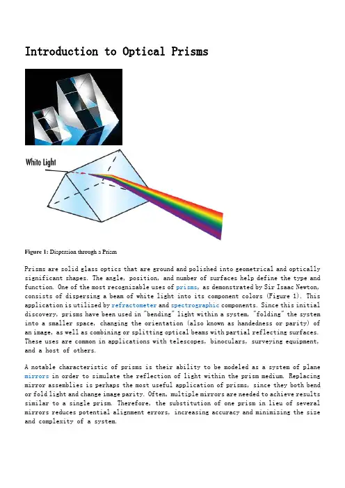
Introduction to Optical PrismsFigure 1: Dispersion through a PrismPrisms are solid glass optics that are ground and polished into geometrical and optically significant shapes. The angle, position, and number of surfaces help define the type and function. One of the most recognizable uses of prisms, as demonstrated by Sir Isaac Newton, consists of dispersing a beam of white light into its component colors (Figure 1). This application is utilized by refractometer and spectrographic components. Since this initial discovery, prisms have been used in "bending" light within a system, "folding" the system into a smaller space, changing the orientation (also known as handedness or parity) of an image, as well as combining or splitting optical beams with partial reflecting surfaces. These uses are common in applications with telescopes, binoculars, surveying equipment, and a host of others.A notable characteristic of prisms is their ability to be modeled as a system of plane mirrors in order to simulate the reflection of light within the prism medium. Replacing mirror assemblies is perhaps the most useful application of prisms, since they both bend or fold light and change image parity. Often, multiple mirrors are needed to achieve results similar to a single prism. Therefore, the substitution of one prism in lieu of several mirrors reduces potential alignment errors, increasing accuracy and minimizing the size and complexity of a system.PRISM MANUFACTURINGBefore delving into the theory behind prisms, consider their manufacturing process. In order to be used successfully in most applications, prisms must be manufactured with very strict tolerances and accuracies. Due to the variability in shape, size, and, most importantly, the number of surfaces, a large-scale automated process for prism manufacturing is quite infeasible. In addition, most high precision prisms tend to be made in low quantities, meaning an automated process would be unnecessary.First, a block of glass (known as a "blank") of a specified grade and glass type is obtained. This block is then ground, or generated, by a metal diamond bonded wheel into anear-finished product. A majority of the glass is removed quickly in this stage resulting in flat, but still coarse surfaces (Figure 2a). At this point, the dimensions of the prism-to-be are very close to the desired specifications. Next is a fine grinding process that removes sub-surface breaks from the surface; this stage is known as smoothening. Scratches left from the first stage are removed in the second stage (Figure 2b). After smoothening, the glass surfaces should appear cloudy and opaque. In both the first two stages, the prism surface must be wet in order to expedite glass removal and prevent overheating of the glass itself.The third stage involves polishing the prism to the correctly specified surface accuracy. In this stage, the glass is rubbed against a polyurethane polisher wet with "slurry," an optical polishing compound typically comprised of water mixed with pumice or cerium oxide (Figure 2c). The exact duration of the polishing stage is highly dependent on the surface specifications required. Once polishing is completed, chamfering can begin. In this fourth stage, the edges of the prism are subjected to a spinning diamond plate in order to slightly dull the sharp edges it obtains throughout the aforementioned steps (Figure 2d). After chamfering, the finished prism is cleaned, inspected (via both manual and automated means), and coated with anti-reflection (AR) and/or metallic mirror coatings, if necessary, to further aid in overall transmission and/or reflection. Though the process is much more involved and may require more iterations or operations due to the number of surfaces on a prism, the Generating, Smoothening, Polishing and Chamfering Stages are roughly outlined in Figures 2a - 2d.Figure 2a: Prism Manufacturing Process: Generating StageFigure 2b: Prism Manufacturing Process: Smoothening StageFigure 2c: Prism Manufacturing Process: Polishing StageFigure 2d: Prism Manufacturing Process: Chamfering StageThroughout the manufacturing of a prism, it is necessary to continually adjust and secure each surface being worked on. Securing a prism in place involves one of two methods: blocking and contacting. Blocking entails arranging the prism in a metal tool with hot wax. Contacting, on the other hand, is an optical bonding process done at room temperature where two clean glass surfaces are fastened together simply through their Van Der Waals interaction. Contacting is utilized if high precision tolerances are required because it does not require additional adjustments to be made during the Generating, Smoothening, or Polishing Stages to account for the wax thickness between the prism surface and the contact block.During every stage of the prism manufacturing process, from generating to blocking and contacting, a skilled optician is required to manually inspect and adjust the prism surfaces being worked on. As a result, it is extremely labor intensive and requires experience and skill in order to complete. The entire process often requires a significant amount of time, work, and concentration.THEORY: LIGHT AND REFRACTIONUnderstanding how a prism works is key to deciding which type of prism fits best for a specific application. In order to do so, it is important to first understand how light interacts with an optical surface. This interaction is described by Snell's Law of Refraction:(1)Where n1 is the index of the incident medium, θ1 is the angle of the incident ray, n2 is the index of the refracted/reflected medium, and θ2is the angle of the refracted/reflected ray. Snell's Law describes the relationship between the angles of incidence and transmission when a ray travels between multiple media (Figure 3).Figure 3: Snell's Law and Total Internal ReflectionA prism is notable for its ability to reflect the ray path without the need for a special coating, such as that required when using a mirror. This is achieved through a phenomenon known as total internal reflection (TIR). TIR occurs when the incident angle (angle of the incident ray measured from normal) is higher than the critical angle θc:(2)Where n1 is the index of refraction for the medium where the ray originates, and n2 is the index of refraction for the medium where the ray exits. It is important to note that TIR only occurs when light travels from a high index medium to a low index medium.At the critical angle, the angle of refraction is equal to 90°. Referencing Figure 3, notice that TIR occurs only if θ exceeds the critical angle. If the angle is below the critical angle, then transmission will occur along with reflection as given by Snell's Law. If a prism face does not meet TIR specifications for the desired angle(s), then a reflective coating must be used. This is why some applications require coated versions of a prism that would otherwise work well uncoated in another application.Figure 4: Right Handedness or Even ParityFigure 5: Left Handedness or Odd ParityTHEORY: IMAGE HANDEDNESS/PARITYA significant aspect of imaging through a prism is image handedness (parity), otherwise referred to as the orientation of the image. This is introduced every time the ray path hits a plane mirror, any flat reflective surface, or a prism surface at an angle that produces TIR. There are two types of handedness: right and left. Right handedness (Figure 4) describes the case where an image undergoes an even number of reflections, resulting in the ability to read it clearly (assuming the image is text) in at least one position. Left handedness (Figure 5) describes the case where the image undergoes an odd number of reflections, leading to an irregularity in the position of the image that is comparable to what one sees in a mirror.In addition to parity, there are three types of image change (Figure 6). An inversion is an image-flip over a horizontal axis, whereas a reversion is an image-flip over a vertical axis. When both are done at the same time, an image rotation of 180° occurs and there is no change in parity. Another way to think of parity is defining it as being determined by looking back against the propagation direction towards either the object or image in its optical space (Figure 7).When using a prism, consider the following four points:1.Image Handedness Changes Every Time an Image is Reflected.2.Any Point along the Plane of the Reflecting Surface is Equidistant from the Object and Its Image.3.Snell's Law Can Be Applied to All Surfaces.4.When Testing for Image Handedness/Parity, It is Best to Use a Non-Symmetrical Letter Such as R, F, or Q.Avoid Using Letters Like X, O, A, etc.Figure 6: Inversion (Top), Reversion (Middle), Rotation (Bottom)Figure 7: How Parity is DeterminedTYPES OF PRISMSThere are four main types of prisms: dispersion prisms, deviation, or reflection prisms, rotation prisms, and displacement prisms. Deviation, displacement, and rotation prisms are common in imaging applications; dispersion prisms are strictly made for dispersing light, therefore not suitable for any application requiring quality images.Figure 8: Dispersion through a PrismDispersion PrismsPrism dispersion is dependent upon the geometry of the prism and its index dispersion curve, based on the wavelength and index of refraction of the prism substrate. The angle of minimum deviation dictates the smallest angle between the incident ray and the transmitted rays (Figure 8). The green wavelength of light is deviated more than red, and blue more than both red and green; red is commonly defined as 656.3nm, green as 587.6nm, and blue as 486.1nm.Deviation, Rotation, and Displacement PrismsPrisms that deviate the ray path, rotate the image, or simply displace the image from its original axis are helpful in many imaging systems. Ray deviations are usually done at angles of 45°, 60°, 90°, and 180°. This helps to con dense system size or adjust the ray path without affecting the rest of the system setup. Rotation prisms, such as dove prisms, are used to rotate an image after it is inverted. Displacement prisms maintain the direction of the ray path, yet adjust its relation to the normal.Prism Selection GuideTo aid in selecting the best prisms for specific applications, consider the following selection guide of the most commonly used in the optics, imaging, and photonics industries.This introduction gave a look into the manufacturing process and the theory associated with prisms, as well as a selection to help you find the best prism for your application. To learn some examples of prism applications, view Optical Prism Application Examples.。


光学测量棱镜
共有四种主要类型的棱镜:色散棱镜、偏转或反射棱镜、旋转棱镜和偏移棱镜。
偏转、偏移和旋转棱镜常用于成像应用;扩散棱镜专用于色散光源,因此不适合用于要求优质图像的任何应用。
色散棱镜
根据棱镜基片的波长和反射率,棱镜色散取决于棱镜的几何及其折射率色散曲线。
最小偏向角决定入射光线和投射光线之间的最小夹角(图8)。
绿色光的波长偏离超过红色,蓝色比红色和绿色多;红色通常定义为656.3nm,绿色为587.6nm和蓝色为486.1nm。
偏转、旋转和偏移棱镜
偏转光线路径的棱镜,或将图像从其原始轴偏移,在很多成像系统中很有帮助。
光线通常在45°、60°、90°和180°角度偏转。
这有助于聚集系统大小或调整光线路径而不影响其余的系统设置。
旋转棱镜,例如道威棱镜,用于旋转倒位后的图像。
偏移棱镜保持光线路径的方向,还会将其关系调整为正常。
附录
实物光路
•
•
•
•
•
•
••
••
•••
••
••
••。

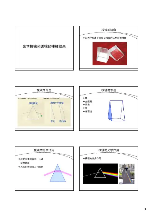
棱镜物理原理棱镜是一种常用的光学器件,它由透明介质制成,其两个大平面(称为底面)之间的其它平面(称为棱)是以恒定的角度相交的。
棱镜可以对光进行折射、偏转和分光等操作,因此在光学领域有着广泛的应用。
棱镜的物理原理主要涉及到光的折射和反射。
当一束光线从一个介质进入另一个介质时,如果两个介质的折射率不同,光线会发生折射。
折射是光线改变传播方向的现象,其原理可以用斯涅耳定律来描述。
斯涅耳定律指出,入射光线与法线的入射角和折射光线与法线的折射角之间存在着简单的关系:\[\frac{\sin\thetai}{\sin\thetao}=\frac{v_1}{v_2}\]其中,θi表示入射角,θo表示折射角,v1表示入射介质的光速,v2表示折射介质的光速。
由此可见,当光线从一个折射率较大的介质进入一个折射率较小的介质时,光线会向法线弯曲;相反,当光线从一个折射率较小的介质进入一个折射率较大的介质时,光线会远离法线弯曲。
根据棱镜的形状和材料不同,棱镜可以分为三角棱镜、矩形棱镜、菱形棱镜等多种类型。
其中,最常见的是三角棱镜,它由两个底面和三个棱组成,底面之间的夹角决定了光线在棱镜中的路径。
我们来看一个应用折射原理的例子,如何将一个白光分解成七色光。
这就是通过光的折射和色散完成的。
挤压上凸凹面,使它像一个三角形一样,称作棱镜。
当光线自空气进入棱镜时,由于光的波长不同,折射率也不同,因此光线在棱镜中发生折射,使不同波长的光偏离原来的方向。
之后,光线再次折射出来,不同波长的光根据折射率不同再次偏离原来的方向,最终形成七种颜色的光线,即红、橙、黄、绿、青、蓝和紫色。
此外,棱镜还可以用于测量折射率和分辨光谱等应用。
使用不同材料或形状的棱镜,可以实现对光的不同处理效果。
例如,玻璃棱镜的折射率较高,适用于对光线进行大角度的折射和准直;石英棱镜的折射率较低,适用于对光线进行小角度的折射和分光。
总结起来,棱镜物理原理主要基于光的折射和反射现象。


光学棱镜分光原理:光波在棱镜中的折射与分离
光学棱镜分光是利用棱镜对光波的折射特性进行光谱分离的原理。
这个过程包括把白光或混合波通过棱镜,然后不同波长的光在折射时发生不同的弯曲,从而分离成不同颜色的光谱。
以下是光学棱镜分光的基本原理:
入射光波:入射的光波可以是单色光或混合波(例如白光)。
这个光波通过棱镜。
折射:入射的光波在通过棱镜表面时会发生折射。
折射的程度取决于光波的波长。
根据光的折射定律,不同波长的光在折射后会有不同的角度。
色散:不同波长的光在折射后分散开来,形成光谱。
这是因为折射角与波长之间存在一种关系,称为色散关系。
分离:光谱中的不同颜色被分离开来,形成一个连续的颜色条带,称为光谱带。
彩虹效应:这个过程类似于彩虹的形成,其中雨滴分散阳光,使不同波长的光以不同的角度折射,形成彩虹。
光学棱镜分光的应用非常广泛,包括在物理学、化学、天文学等领域。
分光仪和光谱仪就是利用这个原理来分析和测量光谱的仪器。

光学系统中棱镜的用法
在光学系统中,棱镜是一种重要的光学元件,它可以改变光线的传播方向。
以下是棱镜在光学系统中的一些常见用法:
1. 分束:棱镜可以将一束光线分成多束光线,每束光线具有不同的方向和偏振状态。
这种用法在光学测量、光学通信等领域非常有用。
2. 偏振:棱镜可以改变光线的偏振状态,使得光线在某些方向上振动较强,而在其他方向上振动较弱。
这种用法在光学成像、光学干涉等领域非常有用。
3. 反射:棱镜可以反射光线,使得光线按照一定的角度反射出去。
这种用法在反射式望远镜、激光器等领域非常有用。
4. 折射:棱镜可以改变光线的折射率,使得光线按照一定的角度折射出去。
这种用法在透镜、折射式望远镜等领域非常有用。
总之,棱镜在光学系统中具有多种用途,可以根据具体的应用场景和需求选择合适的棱镜类型和用法。

眼镜棱镜图全解什么是眼镜的棱镜效应?⽹上配镜专家告诉您,只要眼睛的视觉通道与镜⽚的光学中⼼有偏差,就会产⽣棱镜效应。
所以处⽅正确的眼镜是否加⼯正确整形正确,可以⽤产⽣棱镜效应的严重程度来衡量。
下⾯我们就通过图形来解释眼镜的棱镜效应。
P=F× C(cm)P:表⽰棱镜F:表⽰屈光度C:表⽰光⼼偏离距离,单位(cm)红点表⽰瞳孔距离。
蓝点表⽰镜⽚光中⼼。
例:双眼度数-5.00D,PD:64mm,两个镜⽚的光学中⼼(PD)=72mm,请问这时候会产⽣多少棱镜效应?其基底的⽅向为何?解:72-64=8mmP=5× 0.8=4△BI(基底朝内)答:双眼4△BI例:双眼度数+4.00D,PD:64mm,两个镜⽚的光学中⼼(PD)=72mm,请问这时候会产⽣多少棱镜效应?其基底的⽅向为何?解:72-64=8mmP=4× 0.8=3.2△BO答:双眼3.2△BO例:双眼度数为-5.00D,左眼镜⽚光学中⼼位于瞳孔上⽅4mm,请问这时候会产⽣多少棱镜效应?其基底的⽅向为何?解:P=5× 0.4=2△BD(基底朝下)答:左眼2△BD例:双眼度数为+4.00D,右眼镜⽚光学中⼼位于瞳孔上⽅6mm,请问这时候会产⽣多少棱镜效应?其基底的⽅向为何?解:P=4×0.6=2.4△BU答:右眼2.4△BU例:右眼-3.50D,右眼镜⽚光学中⼼位在瞳孔上⽅3mm、⽿侧6mm,请问这时候会产⽣多少棱镜效应?其基底的⽅向为何?解:(⽔平)PH=3.5×0.6=2.1△BI(垂直)Pv=3.5×0.3=1.05△BD答:右眼2.1△基底朝内及1.05△基底朝下例:右眼:S-4.00C-2.00Ax180°;左眼:S-4.00C+2.00Ax180°右眼镜⽚光⼼偏离瞳孔中⼼外侧5mm,左眼镜⽚光⼼偏离瞳孔中⼼上侧5mm,将各⾃产⽣多少棱镜效应?各⾃基底的⽅向为何?解:先以光学⼗字法求得各主径线度数右眼如下:右眼:P=4× 0.5=2△BI左眼如下:左眼:P=2× 0.5=1△BD答:右眼2△基底朝内,左眼1△基底朝下例:左眼S-2.00C-1.50Ax70°,左眼镜⽚光⼼偏离瞳孔中⼼内侧5mm,请问这时候左眼会产⽣多少棱镜效应?其基底的⽅向为何?解:先画出光学⼗字法求得⽔平⽅向的度数答:镜⽚180°轴的度数:(-2.00)+(-1.50)sin² × 70°=-3.32DP=3.32× 0.5=1.66△BO(基底朝外)。
1棱镜度的意思
在光学领域,"棱镜度"是一个常用来描述棱镜性能的参数。
那么,1棱镜度的意思究竟是什么呢?本文将为您详细解释。
一、棱镜度定义
棱镜度(Prism Power)是衡量棱镜折射光线能力的单位,通常用“Δ”(希腊字母Delta)表示。
1棱镜度意味着当光线通过棱镜时,光线偏离原来方向的角度为1秒(1/60度)。
二、棱镜度的计算
棱镜度可以通过以下公式计算:
棱镜度(Δ)= (n - 1)× a
其中,n为棱镜材料的折射率,a为棱镜的顶角(单位:弧度)。
当棱镜度Δ=1时,表示光线通过棱镜后偏离原来方向1秒。
三、1棱镜度的实际意义
1棱镜度意味着当光线垂直入射到棱镜上,通过棱镜后,光线的偏离角度为1秒。
在实际应用中,1棱镜度的折射能力相对较小,通常用于校正轻微的视力问题,如轻微的斜视。
四、棱镜度的应用
1.眼镜:对于有斜视或其他视觉问题的患者,可以通过配置具有适当棱镜度的眼镜来校正视力。
2.光学仪器:棱镜在光学仪器中具有广泛的应用,如望远镜、显微镜等,通过调整棱镜度来改善图像质量。
3.光学实验:在物理实验中,棱镜度可以用来研究光的折射、散射等现象。
总结:1棱镜度是一个描述棱镜折射光线能力的单位,表示光线通过棱镜后偏离原来方向1秒。
棱镜度在眼镜、光学仪器和实验等领域具有广泛的应用。
光学棱镜成像规律归纳总结
光学棱镜是一种常用的光学元件,具有广泛的应用。
在使用光
学棱镜进行成像时,遵循一些基本规律可以帮助我们获得清晰的图像。
1.光线传播规律
光线在进入光学棱镜后会发生折射或反射。
根据光的传播路径,我们可以将光线分为入射光线、折射光线和反射光线。
2.焦距与成像规律
光学棱镜可以将入射光线聚焦到一点上,这个点称为焦点。
焦
点的位置与棱镜的形状、折射率以及入射角度有关。
3.成像位置与放大率
使用光学棱镜进行成像时,物体的位置和放大率是重要的参考
指标。
物体距离棱镜的远近和放大率之间存在一定的关系,可以根
据需求进行调节。
4.色散现象
光学棱镜对不同波长的光有不同的折射率,导致光线在通过棱镜时发生偏折。
这种现象称为色散,是光学棱镜成像中需要注意的特点之一。
以上是光学棱镜成像规律的归纳总结,这些规律可以帮助我们深入理解光学棱镜的工作原理和应用。
在实际应用中,我们可以根据这些规律进行设计和优化,以达到预期的成像效果。
光学棱镜用途
光学棱镜是一种常见的光学元件,它可以将光线折射、反射、分离、合并等,因此在许多领域都有广泛的应用。
光学棱镜在光学仪器中被广泛使用。
例如,在显微镜中,光学棱镜可以将光线折射,使得观察者可以看到更清晰的图像。
在望远镜中,光学棱镜可以将光线反射,使得观察者可以看到更远的天体。
在激光器中,光学棱镜可以将激光束分离成多个束,从而实现多束激光器的功能。
光学棱镜在光学通信中也有重要的应用。
在光纤通信中,光学棱镜可以将光线分离成多个波长,从而实现多波长光纤通信。
在光学调制解调器中,光学棱镜可以将光线分离成两个方向,从而实现光学调制解调的功能。
光学棱镜还在光学实验中被广泛使用。
例如,在干涉仪中,光学棱镜可以将光线分离成两个方向,从而实现干涉实验。
在光谱仪中,光学棱镜可以将光线分离成多个波长,从而实现光谱分析。
光学棱镜是一种非常重要的光学元件,它在光学仪器、光学通信、光学实验等领域都有广泛的应用。
随着科技的不断发展,光学棱镜的应用也将越来越广泛。