MOXAPT7728
- 格式:doc
- 大小:199.50 KB
- 文档页数:20

P/N: 1802000021022*1802000021022*ABC-02-USB Quick Installation GuideAutomatic Backup ConfiguratorEdition 2.1, July 2019Technical Support Contact Information/support Moxa Americas:Toll-free: 1-888-669-2872Tel: 1-714-528-6777Fax: 1-714-528-6778 Moxa China (Shanghai office): Toll-free: 800-820-5036 Tel: +86-21-5258-9955 Fax: +86-21-5258-5505 Moxa Europe:Tel: +49-89-3 70 03 99-0Fax: +49-89-3 70 03 99-99 Moxa Asia-Pacific: Tel: +886-2-8919-1230 Fax: +886-2-8919-1231 Moxa India:Tel: +91-80-4172-9088Fax: +91-80-4132-10452019 Moxa Inc. All rights reserved.OverviewThe ABC-02-USB Automatic Backup Configurator is a device that can save and load configuration files, backup event logs, and load firmware of Moxa’s managed switch via the USB (universal serial bus) interface. The ABC-02-USB is able to be accessed directly like a standard USB flash drive from a computer.The ABC-02-USB makes it easier to manage the backup of system parameters or perform configuration during the replacement of a switch. With the ABC-02-USB, users can quickly re-install a substitute switch (of the same model) without the need of a laptop computer. The ABC-02 can be used to recover the entire system configuration, including the IP address, if a switch failure occurs.Switches can load firmware from the ABC-02-USB and backup event logs to the ABC-02-USB. It is also an easy and fast diagnostics tool for automation engineers to retrieve configuration files and event logs in the field immediately, without the need for laptop computers. Package ChecklistThe ABC-02-USB is shipped with the following items. If any of these items is missing or damaged, please contact your customer service representative for assistance.• 1 x ABC-02-USB•Quick installation guide (printed)•Warranty cardFeatures•Widely used USB 2.0 interface•Click the switch rest button to back up the configuration file and event log to ABC-02•Automatic loading of system configuration after system reboot •Manual upgrade firmware from ABC-02 and backup event logs to ABC-02•Manual and saving system configuration through web console •Extend switch event log storage capability•Portable low-power design that requires no power supply•CE, FCC approvalHardware DescriptionProduct InstallationThe ABC-02-USB is designed for use with an USB 2.0 port. Plug the ABC-02 into the USB port of your Moxa managed switch. Securing the ABC-02 on the wall with an M4 screw is suggested.Avoid hanging the ABC-02 configurator from the switch without securing it onto the wall.Please refer to the Product Operation section for instructions on how to save and load the configuration, firmware, and event logs. Product OperationConfiguration Backup and Restore•Backup switch configuration on the ABC-02Use the switch web console to save the configuration file to theABC-02. This function is found under “System/System Files/Configuration Backup and Restore “. Then select “Auto BackupConfigurator (ABC-02)” in the web console. Click “Backup” to save the configuration file to the ABC-02. The file will be saved in the“:\Moxa” folder of the ABC-02. The file name is “Sys.ini”. •Restore the configuration file from the ABC-02 to the switchA. Manually operate in web consoleUse the switch web console to load configuration files from theABC-02 to the switch. This function is found under“System/System Files/ Configuration Backup and Restore”.Then select “Auto Backup Configurator (ABC-02)” in the webconsole. Click “Browse” to select the file you need. Then click“Restore” to start loading into your switch.B. Auto-load the configuration file from the ABC-02 to the systemwhen the switch boots upPower off your switch first, and then plug in the ABC-02. Thenpower on your switch, the system will detect the configurationfile on the ABC-02 automatically. The switch will recognize thefile name with following sequence priority:1. ”MAC address last 6 digits.ini*”2. “Sys.ini”. If no matching configuration file is found, the faultLED light will turn on. The switch will boot up normally.NOTE Please save your configuration files in the “:\Moxa” folder of the ABC-02. Auto-load will detect the configuration file using thispath only.Firmware UpgradeUpgrade the firmware from the ABC-02 to the switch. You can download the firmware file from /support/. Save the firmware file in the “:\Moxa” folder of the ABC-02.Plug in the ABC-02 into your switch. Use the switch web console to load the switch firmware file from the ABC-02. This function is found under “System/System Files/ Firmware Upgrade “. Then select “Auto Backup Configurator (ABC-02)” in the web console. Click “Browse” to select the file you need. Then click “Upgrade” to start loading the file into your switch.Log File BackupBackup the switch log file to the ABC-02Use the switch web console to save the configuration file to the ABC-02. This function is found under “System/System Files/ Log File Backup “. Then select “Auto Backup Configurator (ABC-02)” in the web console. Click “Backup” to save the configuration file to the ABC-02. The log file will be saved in the “:\Moxa” folder of the ABC-02. The file will be named “Sys.log”.One-click backupThe ABC-02 can backup configuration and log files from the switch. When the ABC-02 is plugged into the switch, “STATE” LEDs on the switch will start to blink slowly, and the reset function will be disabled automatically. Press the “reset” button once and the switch will start backing up configuration files and system logs to the ABC-02.The “RESET” button is located on the front panel of rackmount type switches and on the top panel of DIN-rail type switches.Auto backup to the ABC-02 when configurations changeThe ABC-02 is capable of backing up switch configuration files automatically. This function is found under “System/System Files/ Configuration Backup and Restore”. While the ABC-02 is plugged into the switch, enable the “Auto backup to ABC-02 when configuration change” option. Then click “Apply”. Once this configuration is modified, the switch will back up the current configuration under the “/His_ini” folder in the ABC-02. The file name will be the system date/time (MMDDHHmm.ini).Auto backup of the earliest 100 log entries to prevent overwritingThis function is designed to maintain a long-term record the switch log files. Moxa Ethernet switches are capable of saving 1000 entries of event logs. When the 1000-entry storage limit is reached, the switch will delete the oldest saved event log. The ABC-02 can help to backup these event logs. When switch log entries reach 1000, the ABC-02 will back up the earliest 100 entries of the switch.The function is found under “System/System Files/ Log File Backup”. Enable the “Auto backup the earliest 100 log entries to prevent overwriting”. Then click “Apply”. After that, when the ABC-02 is plugged into the switch, the event logs will always be saved to the ABC-02 automatically.NOTE For further details on the ABC-02 operation through the switch web console, please refer to the switch user manual.NOTE The status of the ABC-02 may be checked on the switch web console or by observing the switch front panel LEDs.Operation Switch LED statusThe switch detects ABC-02-USB plugged in STATE blinking slowly (1 time/ 2 seconds),Import/Export in progress* FAULT, MASTER, COUPLER LEDs Blink sequentially and circularlyImport/Export successful FAULT, MASTER, COUPLER LEDs light offSave/Load failed FAULT LED light on until ABC-02 isremoved or system rebootOperation ABC-02 LED status Power on ABC-02 STATE LED green light on Reading /Writing ABC-02 STATE LED blinking*Does not include “Auto backup to the ABC-02 when configuration change” and ”Auto backup the earliest 100 log entries to prevent overwritingSpecificationsOperating Temperature 0 to 60°C (32 to 140°F)Storage Temperature -40 to 85°C (-40 to 185°F) Connectors RS-232 RJ45 portPower Requirement 3 to 5 VDC, power input via RS-232 RTS Configuration via Moxa managed switch’s web console Casing PVC molding, IP40Weight 50 gInstallation M4 screw (> 4 mm)Dimension (W × D × H) 32.5 × 97 × 12 mmCable Length 35 cm, including connectors Operating Temperature 0 to 60°C (32 to 140°F)Storage Temperature -20 to 70°C (-4 to 158°F)Ambient Relative5 % to 95 % (non-condensing) HumidityEMI FCC Part 15, CISPR (EN55032) Class A EMS EN61000-4-2 (ESD), level 3EN61000-4-3 (RS), level 3EN61000-4-4 (EFT), level 3EN61000-4-5 (Surge), level 3EN61000-4-6 (CS), level 3Warranty 5 years。

TAP-213系列軌道用車載802.11n IP68無線AP/用戶端特色與優點•符合IEEE802.11a/b/g/n規範•可由冗餘雙直流電源輸入或PoE供電•QoS(WMM)和VLAN提供有效率的網路流量•基於控制器的Turbo Roaming(小於50毫秒)1•符合所有EN50155標準強制性測試項目2•IP68等級堅固外殼,支援-40至75°C的操作溫度•無線網路冗餘加上AeroLink保護認證簡介TAP-213無線Ap/用戶端對於軌道車載系統和列車對地通訊應用(例如CCTV和CBTC通訊)來說,是理想的堅固型無線方案。
TAP-213的防塵防風雨設計達到IP68等級,讓您將無線網路延伸至戶外地點與嚴苛環境。
兩組直流電源(DC)輸入增加了電源供應器的可靠度,裝置也可透過PoE供電,讓現場布線更方便。
TAP-213符合EN50155標準的強制性測試項目,確保適合軌道車輛應用。
TAP-213具備許多強化的工業級功能,提供穩定可靠的無線連線能力,特別適用於軌道車載環境。
針對嚴苛環境的特點•IP68等級金屬外殼,支援-40至75°C的寬操作溫度•M12防震設計,同時具備防水防塵特性•PoE及雙直流電源輸入•高功率400mW(最大值)無線發射率•介於24至110直流電壓(VDC)的寬廣電源輸入範圍•若為用戶端,Turbo Roaming快速漫遊在3個頻道及WPA2時,切換時間少於150毫秒•若為控制端,Turbo Roaming快速漫遊(僅限和WAC-1001或WAC-2004用時)在3個頻道及WPA2時,切換時間少於50毫秒•多種漫遊參數,適用於不同的安裝架構和天線類型規格WLAN InterfaceChannel Bandwidth5MHz,10MHz,20MHz,40MHzFrequency Band for EU(20MHz operating channels) 2.412to2.472GHz(13channels)5.180to5.240GHz(4channels)5.260to5.320GHz(4channels)5.500to5.700GHz(11channels)Frequency Band for JP(20MHz operating channels) 2.412to2.484GHz(14channels)5.180to5.240GHz(4channels)5.260to5.320GHz(4channels)5.500to5.700GHz(11channels)Frequency Band for US(20MHz operating channels) 2.412to2.462GHz(11channels)1.此處所指的Turbo Roaming快速漫遊復原時間是在最佳狀態下,配置無干擾20MHz RF頻道、WPA2-PSK安全性和預設的Turbo Roaming快速漫遊參數,所得到的測試結果平均值。

UC-8200系列Arm Cortex-A7雙核心1GHz IIoT閘道,內建LTE Cat.4,1個用於Wi-Fi模組的迷你PCIe擴充插槽,1個CAN連接埠、4個DI、4個DO特色與優點•Armv7Cortex-A7雙核心1GHz•Moxa工業Linux,提供10年超長期間支援•LTE規格電腦,獲得Verizon/AT&T認證以及工業級CE/FCC/UL認證•雙SIM插槽•2個自動感應10/100/1000Mbps乙太網路連接埠•整合式LTE Cat.4模組,支援US/EU/APAC頻帶•1個CAN連接埠,可支援CAN2.0A/B•具有microSD插槽,可擴充儲存空間•配備可程控LED以及可程控按鈕,讓您輕鬆地完成安裝與維護•-40至85°C寬溫範圍設計,啟用LTE時溫度範圍為-40至70°C認證簡介UC-8200運算平台是專為嵌入式資料擷取應用所設計。
電腦配備兩個RS-232/422/485串列埠、雙10/100/1000Mbps乙太網路連接埠、一個CAN連接埠,以及雙Mini PCIe插槽以支援Wi-Fi/行動通訊網路模組。
這些多元功能讓使用者能有效地調整UC-8200以適應各種複雜通訊解決方案。
UC-8200採用的是專為能源監視系統進行最佳化的Cortex-A7雙核心處理器,但是該處理器目前已被廣泛地用於各種工業解決方案。
這款輕薄的嵌入式電腦是可靠且安全的閘道,具備彈性的介面選項,可協助您在現場進行資料擷取並進行處理,同時也是適用於許多其他大規模部署的實用通訊平台。
已啟用LTE的寬溫度型號可用於延伸的溫度應用。
所有裝置全都在試驗室中經過完整測試,保證已啟用LTE的運算平台適用於寬溫應用。
外觀UC-8210UC-8220規格ComputerCPU Armv7Cortex-A7dual-core1GHzDRAM2GB DDR3LStorage Pre-installed8GB eMMCPre-installed OS Moxa Industrial Linux(Debian9,Kernel4.4)See /MILExpansion Slots MicroSD(SD3.0)socket x1Computer InterfaceTPM UC-8210-T-LX-S:TPM v2.0UC-8220-T-LX-AP-S:TPM v2.0UC-8220-T-LX-EU-S:TPM v2.0UC-8220-T-LX-US-S:TPM v2.0Ethernet Ports Auto-sensing10/100/1000Mbps ports(RJ45connector)x2 Serial Ports RS-232/422/485ports x2,software selectable(DB9male) CAN Ports CAN2.0A/B x1(DB9male)Digital Input DIs x4Digital Output DOs x4USB2.0USB2.0hosts x1,type-A connectorsWi-Fi Antenna Connector RP-SMA x2(UC-8220only)Cellular Antenna Connector SMA x2(UC-8220only)GPS Antenna Connector SMA x1(UC-8220only)Expansion Slots mPCIe slot x2(UC-8220-T-LX)mPCIe slot x1(UC-8220-T-LX US/EU/AP models)SIM Format Nano(UC-8220only)Number of SIMs2(UC-8220only)Buttons Programmable buttonEthernet InterfaceMagnetic Isolation Protection 1.5kV(built-in)Serial InterfaceConsole Port1x4-pin header to DB9console portBaudrate300bps to921.6kbpsData Bits5,6,7,8Parity None,Even,Odd,Space,MarkStop Bits1,1.5,2Serial SignalsRS-232TxD,RxD,RTS,CTS,DTR,DSR,DCD,GNDRS-422Tx+,Tx-,Rx+,Rx-,GNDRS-485-2w Data+,Data-,GNDRS-485-4w Tx+,Tx-,Rx+,Rx-,GNDCAN InterfaceNo.of Ports1Connector DB9maleBaudrate10to1000kbpsIndustrial Protocols CAN2.0A,CAN2.0BIsolation2kV(built-in)Signals CAN_H,CAN_L,CAN_GND,CAN_SHLD,CAN_V+,GNDDigital InputsConnector Screw-fastened Euroblock terminalDry Contact Off:openOn:short to GNDIsolation3K VDCSensor Type Wet contact(NPN)Dry contactWet Contact(DI to COM)On:10to30VDCOff:0to3VDCDigital OutputsConnector Screw-fastened Euroblock terminalCurrent Rating200mA per channelI/O Type SinkVoltage24VDC nominal,open collector to30VDCCellular InterfaceCellular Standards LTE CAT-4Band Options US model:LTE Bands:Band2(1900MHz)/Band4(1700MHz)/Band5(850MHz)/Band13(700MHz)/Band14(700MHz)UMTS Bands:Band2(1900MHz)/Band5(850MHz)Carrier Approval:Verizon,AT&TEU model:LTE Bands:Band1(2100MHz)/Band3(1800MHz)/Band5(850MHz)/Band7(2600MHz)/Band8(900MHz)/LTE Band20(800MHz)UMTS Bands:Band1(2100MHz)/Band2(1900MHz)/Band5(850MHz)/Band8(900MHz)AP model:LTE Bands:Band1(2100MHz)/Band3(1800MHz)/Band5(850MHz)/Band7(2600MHz)/Band8(900MHz)/Band28(700MHz)UMTS Bands:Band1(2100MHz)/Band2(1900MHz)/Band5(850MHz)/Band8(900MHz)GPS InterfaceReceiver Types72-channel u-blox M8engineGPS/GLONASS/GalileoAccuracy Position:2.5m CEPSBAS:2.0m CEPAcquisition Aided starts:3secCold starts:26secSensitivity Cold starts:-148dBmTracking:-164dBmTime Pulse0.25Hz to10MHzLED IndicatorsSystem Power x2Programmable x1SIM card indicator x1Wireless Signal Strength Cellular/Wi-Fi x6Power ParametersNo.of Power Inputs Redundant dual inputsInput Voltage12to48VDCPower Consumption10WInput Current0.8A@12VDCReliabilityAlert Tools External RTC(real-time clock)Automatic Reboot Trigger External WDT(watchdog timer)Physical CharacteristicsDimensions141.5x120x39mm(5.7x4.72x1.54in)for UC-8220141.5x120x27mm(5.7x4.72x1.06in)for UC-8210Housing SECCMetalInstallation DIN-rail mounting,Wall mounting(with optional kit)IP Rating IP30Weight UC-8210:560g(1.23lb)UC-8220:750g(1.65lb)Environmental LimitsAmbient Relative Humidity5to95%(non-condensing)Operating Temperature UC-8210-T-LX:-40to85°C(-40to185°F)UC-8210-T-LX-S:-40to85°C(-40to185°F)UC-8220-T-LX:-40to70°C(-40to158°F)UC-8220-T-LX-US-S:-40to70°C(-40to158°F)UC-8220-T-LX-EU-S:-40to70°C(-40to158°F)UC-8220-T-LX-AP-S:-40to70°C(-40to158°F)Storage Temperature(package included)-40to85°C(-40to185°F)Shock IEC60068-2-27Vibration2Grms@IEC60068-2-64,random wave,5-500Hz,1hr per axis(without USB devicesattached)Standards and CertificationsSafety UL62368-1,EN62368-1EMC EN55032/35,EN61000-6-2/-6-4EMI CISPR32,FCC Part15B Class AEMS IEC61000-4-2ESD:Contact:4kV;Air:8kVIEC61000-4-3RS:80MHz to1GHz:10V/mIEC61000-4-4EFT:Power:2kV;Signal:1kVIEC61000-4-6CS:10VIEC61000-4-8PFMFIEC61000-4-5Surge:Power:0.5kV;Signal:1kVHazardous Locations Class I Division2,ATEXCarrier Approvals VerizonAT&TGreen Product RoHS,CRoHS,WEEEMTBFTime UC-8210-T-LX:716,739hrsUC-8210-T-LX-S:708,581hrsUC-8220-T-LX:650,836hrsUC-8220-T-LX-US-S:528,574hrsUC-8220-T-LX-EU-S:528,574hrsUC-8220-T-LX-AP-S:528,574hrsStandards Telcordia(Bellcore)Standard TR/SRWarrantyWarranty Period5yearsDetails See /tw/warrantyPackage ContentsDevice1x UC-8200Series computerDocumentation1x quick installation guide1x warranty cardInstallation Kit1x DIN-rail kit(preinstalled)1x power jack6x M2.5mounting screws for the cellular module Cable1x console cable尺寸UC-8210UC-8220訂購資訊Model Name CPU RAM Storage TPM mPCIe Slot1forLTE ModulemPCIe Slot2forWi-Fi ModuleOperatingTemperatureUC-8210-T-LX1GHz Dual Core2GB8GB–––-40to85°C UC-8210-T-LX-S1GHz Dual Core2GB8GB Built-in––-40to85°C UC-8220-T-LX1GHz Dual Core2GB8GB–Reserved Reserved-40to70°CUC-8220-T-LX-US-S 1GHz Dual Core2GB8GB Built-inUS region LTEmodulepreinstalledReserved-40to70°CUC-8220-T-LX-EU-S 1GHz Dual Core2GB8GB Built-inEurope regionLTE modulepreinstalledReserved-40to70°CUC-8220-T-LX-AP-S 1GHz Dual Core2GB8GB Built-inAPAC region LTEmodulepreinstalledReserved-40to70°C配件(選購)Power AdaptersPWR-12150-EU-SA-T Locking barrel plug,12VDC,1.5A,100to240VAC,Continental Europe(EU)plug,-40to75°C operatingtemperaturePWR-12150-UK-SA-T Locking barrel plug,12VDC,1.5A,100to240VAC,United Kingdom(UK)plug,-40to75°C operatingtemperaturePWR-12150-USJP-SA-T Locking barrel plug,12VDC1.5A,100to240VAC,United States/Japan(US/JP)plug,-40to75°Coperating temperaturePWR-12150-AU-SA-T Locking barrel plug,12VDC,1.5A,100to240VAC,Australia(AU)plug,-40to75°C operatingtemperaturePWR-12150-CN-SA-T Locking barrel plug,12VDC,1.5A,100to240VAC,China(CN)plug,-40to75°C operating temperaturePower WiringCBL-PJTB-10Non-locking barrel plug to bare-wire cableCablesCBL-F9DPF1x4-BK-100Console cable with4-pin connector,1mWi-Fi Wireless ModulesUC-8200WiFi-AC Wi-Fi package for UC-8200,includes Wi-Fi module,6screws,1heat sink,1padAntennasANT-LTEUS-ASM-01GSM/GPRS/EDGE/UMTS/HSPA/LTE,omni-directional rubber duck antenna,1dBiANT-LTE-ASM-04BK704-960/1710-2620MHz,LTE omni-directional stick antenna,4.5dBiANT-LTE-OSM-03-3m BK700-2700MHz,multi-band antenna,specifically designed for2G,3G,and4G applications,3m cable ANT-LTE-ASM-05BK704-960/1710-2620MHz,LTE stick antenna,5dBiANT-LTE-OSM-06-3m BK MIMO Multiband antenna with screw-fastened mounting option for700-2700/2400-2500/5150-5850MHzfrequenciesANT-WDB-ARM-0202 2.4/5GHz,panel antenna,2/2dBi,RP-SMA(male)DIN-Rail Mounting KitsUC-8210DIN-rail Mounting Kit DIN-rail mounting kit for UC-8210with4M3screwsUC-8220DIN-rail Mounting Kit DIN-rail mounting kit for UC-8220with4M3screwsWall-Mounting KitsUC-8200Wall-mounting Kit Wall-mounting kit for UC-8200with4M3screws©Moxa Inc.版權所有.2021年8月04日更新。

DA-660A系列基於Arm架構、採用500MHz處理器、具備4個LAN連接埠和8至16個串列埠的1U機架安裝工業電腦特色與優點•MoxaMacro500MHz處理器,具備128MB板载RAM和32MB快閃記憶體•8至16個可由軟體選擇的RS-232/422/485串列埠•8至16個可由跳接器設定的1/150kΩ上拉/下拉電阻和120歐姆終端電阻•所有串列訊號皆具有15kV ESD防護•四個10/100Mbps乙太網路埠•USB和CF插槽,用於擴充儲存空間•標準19吋機架安裝,1U高度•100至240VAC寬壓電源輸入•HMI專用LCM顯示器和鍵盤•可直接執行的Linux作業系統平台•穩定的無風扇設計•提供具有串列埠隔離保護的型號認證簡介DA-660A系列是基於Arm架構、可直接執行的嵌入式電腦,專為工業資料採集應用所設計。
此系列電腦具有8至16個RS-232/422/485串列埠、4個乙太網路連接埠和2個USB2.0連接埠,皆以MoxaMacro通訊處理器為基礎。
此外,DA-662A-I-8/16-LX串列埠具有高度抗干擾保護。
外殼採用標準1U 19英吋寬機架安裝設計,堅固耐用。
而穩固的機架安裝設計則提供工業環境應用所需的強化保護,讓使用者可以輕鬆將DA-660A電腦安裝在標準19吋機架上。
DA-660A電腦非常適合需要分散式嵌入式技術的應用,例如SCADA系統、工廠現場自動化以及電力監控等應用。
外觀Front View(DA-662A-8)Front View(DA-662A-16)Rear View(DA-662A-8)Rear View(DA-662A-16)規格ComputerCPU MoxaMacro500MHzSDRAM128MBFlash NOR Flash,32MBPre-installed OS LinuxLCD Module Liquid Crystal Display on the case,2x16text mode Ethernet InterfaceEthernet Ports Auto-sensing10/100Mbps ports(RJ45connector)x4 Magnetic Isolation Protection 1.5kV(built-in)LED IndicatorsSystem System Ready x1Serial2per port(Tx,Rx)Serial InterfaceSerial Ports8-port models:8x RS-232/422/48516-port models:16x RS-232/422/485Console Port1x RJ45Serial SignalsData Bits5,6,7,8Stop Bits1,1.5,2Parity None,Even,Odd,Space,MarkFlow Control RTS/CTS,XON/XOFF,ADDC®(automatic data direction control)for RS-485,RTS Toggle(RS-232only)Baudrate50bps to921.6kbpsRS-232TxD,RxD,RTS,CTS,DTR,DSR,DCD,GNDRS-422Tx+,Tx-,Rx+,Rx-,GNDRS-485-4w Tx+,Tx-,Rx+,Rx-,GNDRS-485-2w Data+,Data-,GNDPower ParametersInput Voltage100to240VACPower Consumption20WReliabilityAlert Tools Built-in buzzer and RTC(real-time clock)Automatic Reboot Trigger Built-in WDTPhysical CharacteristicsDimensions480x45x237mm(18.9x1.77x9.33in)Weight4,300g(9.56lb)Environmental LimitsOperating Temperature-10to60°C(14to140°F)Storage Temperature(package included)-20to70°C(-4to-158°F)Ambient Relative Humidity5to95%(non-condensing)Vibration1g@IEC-68-2-6,sine wave(resonance search),5-500Hz,1Oct/min,1Cycle,13mins17sec per axisStandards and CertificationsSafety UL60950-1EMC EN61000-6-2/-6-4EMI CISPR22,FCC Part15B Class AEMS IEC61000-4-2ESD:Contact:8kV;Air:15kVIEC61000-4-3RS:80MHz to1GHz:3V/mIEC61000-4-4EFT:Power:1kV;Signal:0.5kVIEC61000-4-5Surge:Power:2kV;Signal:4kVIEC61000-4-6CS:3V/mIEC61000-4-8:1A/mIEC61000-4-11Green Product RoHS,CRoHS,WEEEMTBFTime DA-662A-8-LX:272,913hrsDA-662A-16-LX:177,580hrsDA-662A-16-DP-LX:177,260hrsDA-662A-I-8-LX:268,332hrsDA-662A-I-16-LX:189,455hrsStandards Telcordia(Bellcore)StandardWarrantyWarranty Period5yearsDetails See /tw/warrantyPackage ContentsDevice1x DA-660A Series computerInstallation Kit1x rack-mounting kitCable1x8-pin RJ45to DB9male serial port cable,150cm1x RJ45-to-RJ45cross-over cable,100cm1x8-pin RJ45to DB9female console port cable,150cm6x jumper capDocumentation1x document and software CD1x quick installation guide1x warranty card尺寸訂購資訊Model Name RS-232/422/485Ports RS-485Serial Ports(2-Wire Only)10/100Mbps LAN Ports DA-662A-8-LX8–4DA-662A-16-LX16–4DA-662A-16-DP-LX16–4DA-662A-I-8-LX444DA-662A-I-16-LX4124配件(選購)Power CordsPWC-C7AU-2B-183Power cord with Australian(AU)plug,2.5A/250V,1.83mPWC-C7CN-2B-183Power cord with two-prong China(CN)plug,1.83mPWC-C7EU-2B-183Power cord with Continental Europe(EU)plug,2.5A/250V,1.83mPWC-C7UK-2B-183Power cord with United Kingdom(UK)plug,2.5A/250V,1.83mPWC-C7US-2B-183Power cord with United States(US)plug,10A/125V,1.83mPower AdaptersPWR-24270-DT-S1Power adapter,input voltage90to264VAC,output voltage24V with2.5A DC load©Moxa Inc.版權所有.2020年1月21日更新。

Firmware for PT-7728 Series Release NotesSupported Operating SystemsNotesChangesApplicable ProductsBugs Fixed• Added warning message when default password was not changed.• Encrypted security keys in user interface.• Enhanced RSTP compatibility.• Cross-site scripting vulnerability.• Denial of service attack vulnerability.• Privilege escalation vulnerability.• SSL v2/v3 vulnerability in HTTPS.• Web console cannot be accessed when the SNMP get bulk service is running.• Specific CLI command caused the switch to reboot with default settings.• Adding a new VLAN changed IGMP querier state from disable to enable.• Could not save configurations to the ABC-01 via IE browser.• Corrected RSTP auto-edge behavior.• Rate limit could not be set in web UI.• PTP timestamp error in announce message.• Removed 1588v2 PTP message of IEC 61850 QoS.• Ports on slot 4 back to default setting after system reboot.• Corrected RSTP edge definition in exported configuration file.• Corrected authorization of Radius/TACACS+ login.EnhancementsN/APT-7728-F-24, PT-7728-F-24-24, PT-7728-F-24-48, PT-7728-F-24-HV, PT-7728-F-48, PT-7728-F-48-48, PT-7728-F-48-HV, PT-7728-F-HV, PT-7728-F-HV-HV, PT-7728-F-HV-HV/KC, PT-7728-R-24, PT-7728-R-24-24, PT-7728-R-24-48, PT-7728-R-24-HV, PT-7728-R-48, PT-7728-R-48-48, PT-7728-R-48-HV, PT-7728-R-HV, PT-7728-R-HV-HV, PT-7728-R-HV-HV/KCN/ANew FeaturesN/AN/ASupported Operating SystemsNotesChangesApplicable ProductsBugs FixedN/A• Inaccurate system local time.• Time floating in NTP mechanism.EnhancementsN/APT-7728-F-24, PT-7728-F-24-24, PT-7728-F-24-48, PT-7728-F-24-HV, PT-7728-F-48, PT-7728-F-48-48, PT-7728-F-48-HV, PT-7728-F-HV, PT-7728-F-HV-HV, PT-7728-F-HV-HV/KC, PT-7728-R-24, PT-7728-R-24-24, PT-7728-R-24-48, PT-7728-R-24-HV, PT-7728-R-48, PT-7728-R-48-48, PT-7728-R-48-HV, PT-7728-R-HV, PT-7728-R-HV-HV, PT-7728-R-HV-HV/KCN/ANew FeaturesN/AN/ASupported Operating SystemsNotesChangesApplicable ProductsBugs Fixed• 12 digit product series number.• Fixed bugs on firmware v3.3.EnhancementsN/APT-7728-F-24, PT-7728-F-24-24, PT-7728-F-24-48, PT-7728-F-24-HV, PT-7728-F-48, PT-7728-F-48-48, PT-7728-F-48-HV, PT-7728-F-HV, PT-7728-F-HV-HV, PT-7728-F-HV-HV/KC, PT-7728-R-24, PT-7728-R-24-24, PT-7728-R-24-48, PT-7728-R-24-HV, PT-7728-R-48, PT-7728-R-48-48, PT-7728-R-48-HV, PT-7728-R-HV, PT-7728-R-HV-HV, PT-7728-R-HV-HV/KC• Supports IEC 61850 QoS.• Build-in MMS server based on IEC 61850-90-4 switch data modeling for power SCADA.New FeaturesN/AN/ASupported Operating SystemsNotesChangesApplicable ProductsBugs Fixed• Added web interface for loop-protection enable/disable.• Added web interface for SSH/SSL key generation.• Added SNMP MIB for SFP DDM.• Login failed in CLI mode when password contained a special character.• Hybrid VLAN lacked SNMP MIB object.• SFP DDM displayed inaccurate values.• IEEE 1588 PTP did not function correctly.• IPv6 did not function correctly.EnhancementsN/APT-7728-F-24, PT-7728-F-24-24, PT-7728-F-24-48, PT-7728-F-24-HV, PT-7728-F-48, PT-7728-F-48-48, PT-7728-F-48-HV, PT-7728-F-HV, PT-7728-F-HV-HV, PT-7728-F-HV-HV/KC, PT-7728-R-24, PT-7728-R-24-24, PT-7728-R-24-48, PT-7728-R-24-HV, PT-7728-R-48, PT-7728-R-48-48, PT-7728-R-48-HV, PT-7728-R-HV, PT-7728-R-HV-HV, PT-7728-R-HV-HV/KCN/ANew FeaturesN/AN/ASupported Operating SystemsNotesChangesApplicable ProductsBugs Fixed• Passed ODVA EtherNet/IP certificate.• Added some minor SNMP OIDs.• Enhanced multicast performance.• Added version number in MIB file.• NTP did not synchronize time in default setting.• NTP client function did not work with Windows XP NTP server.• Firmware Upgrade Failed when IEEE 802.1x was enabled.• Switch rebooted when receiving IGMP v3 packets (commonly used in Windows 7).EnhancementsN/APT-7728-F-24, PT-7728-F-24-24, PT-7728-F-24-48, PT-7728-F-24-HV, PT-7728-F-48, PT-7728-F-48-48, PT-7728-F-48-HV, PT-7728-F-HV, PT-7728-F-HV-HV, PT-7728-F-HV-HV/KC, PT-7728-R-24, PT-7728-R-24-24, PT-7728-R-24-48, PT-7728-R-24-HV, PT-7728-R-48, PT-7728-R-48-48, PT-7728-R-48-HV, PT-7728-R-HV, PT-7728-R-HV-HV, PT-7728-R-HV-HV/KCN/ANew FeaturesN/AN/ASupported Operating SystemsNotesChangesApplicable ProductsBugs FixedN/AN/AEnhancementsN/APT-7728-F-24, PT-7728-F-24-24, PT-7728-F-24-48, PT-7728-F-24-HV, PT-7728-F-48, PT-7728-F-48-48, PT-7728-F-48-HV, PT-7728-F-HV, PT-7728-F-HV-HV, PT-7728-F-HV-HV/KC, PT-7728-R-24, PT-7728-R-24-24, PT-7728-R-24-48, PT-7728-R-24-HV, PT-7728-R-48, PT-7728-R-48-48, PT-7728-R-48-HV, PT-7728-R-HV, PT-7728-R-HV-HV, PT-7728-R-HV-HV/KC• RSTP-2004.• MSTP.• NTP Server/Client.• SW 1588 PTPv2.• CLI.• Ethernet/IP.• Hybrid VLAN.• Radius/TACACS+ for both login access and port authentication.• Egress rate limit.• Unknown unicast filtering.• CPU loading.• Changed IP address without rebooting.• DHCP Discover retries forever, or retries for a period of time.• GARP timer adjustment.• Loop-protection.New FeaturesN/AN/ASupported Operating SystemsNotesChangesApplicable ProductsBugs FixedN/AN/AEnhancementsN/APT-7728-F-24, PT-7728-F-24-24, PT-7728-F-24-48, PT-7728-F-24-HV, PT-7728-F-48, PT-7728-F-48-48, PT-7728-F-48-HV, PT-7728-F-HV, PT-7728-F-HV-HV, PT-7728-F-HV-HV/KC, PT-7728-R-24, PT-7728-R-24-24, PT-7728-R-24-48, PT-7728-R-24-HV, PT-7728-R-48, PT-7728-R-48-48, PT-7728-R-48-HV, PT-7728-R-HV, PT-7728-R-HV-HV, PT-7728-R-HV-HV/KC• Supports TurboPack™ 2009 (add new functions for Turbo Chain, IPv6, Modbus/TCP, IEEE 1588PTP, SNMP Inform, LLDP, DHCP Option 82, Firefox, and SSH).• Push Ring Port button when running Turbo Chain, the Chain ports’ LED will activate.• Link Healthy Check on Giga ports for redundant protocols changed from Alarm mode to Polling mode.• Added “VLAN_UNAWARE”,”RSTP_2004”,”CHANGEIP_NOREBOOT”.• Added 10FL and MTRJ module.New FeaturesN/AN/ASupported Operating SystemsNotesChangesApplicable ProductsBugs FixedN/AN/AEnhancementsN/APT-7728-F-24, PT-7728-F-24-24, PT-7728-F-24-48, PT-7728-F-24-HV, PT-7728-F-48, PT-7728-F-48-48, PT-7728-F-48-HV, PT-7728-F-HV, PT-7728-F-HV-HV, PT-7728-F-HV-HV/KC, PT-7728-R-24, PT-7728-R-24-24, PT-7728-R-24-48, PT-7728-R-24-HV, PT-7728-R-48, PT-7728-R-48-48, PT-7728-R-48-HV, PT-7728-R-HV, PT-7728-R-HV-HV, PT-7728-R-HV-HV/KC• Add PM-7200-8SFP compatibility function.• If you want to upgrade the up-to-date firmware, please refer to User's Manual page 3-10 "System File Update" section for detailed instructions.New FeaturesN/AN/ASupported Operating SystemsNotesChangesApplicable ProductsBugs FixedN/AN/AEnhancementsN/APT-7728-F-24, PT-7728-F-24-24, PT-7728-F-24-48, PT-7728-F-24-HV, PT-7728-F-48, PT-7728-F-48-48, PT-7728-F-48-HV, PT-7728-F-HV, PT-7728-F-HV-HV, PT-7728-F-HV-HV/KC, PT-7728-R-24, PT-7728-R-24-24, PT-7728-R-24-48, PT-7728-R-24-HV, PT-7728-R-48, PT-7728-R-48-48, PT-7728-R-48-HV, PT-7728-R-HV, PT-7728-R-HV-HV, PT-7728-R-HV-HV/KC• New release for the PT-7728 Series.New FeaturesN/AN/A。
EDS-208系列8埠入門級非網管型乙太網路交換器特色與優點•10/100BaseT(X)(RJ45連接器)、100BaseFX (多模、SC/ST 連接器)•支援IEEE802.3/802.3u/802.3x •廣播風暴保護•支援鋁軌式安裝•-10至60°C 工作溫度範圍認證簡介EDS-208系列支援IEEE 802.3/802.3u/802.3x ,具有10/100M 、全/半雙工、MDI/MDIX 自動感應RJ45連接埠。
EDS-208系列可在-10至60°C 的額定溫度範圍內運作,並且非常堅固耐用,適合任何嚴苛的工業環境。
此系列交換器可以輕鬆安裝在DIN 軌道和配接箱中。
由於可安裝在DIN 軌道上、工作溫度範圍寬,並且具備含LED 指示燈的IP30外殼,這款即插即用的EDS-208交換器不僅簡單易用又具可靠性。
規格Ethernet InterfaceStandardsIEEE 802.3for 10BaseTIEEE 802.3u for 100BaseT(X)and 100BaseFX IEEE 802.3x for flow control 10/100BaseT(X)Ports (RJ45connector)Auto MDI/MDI-X connection Full/Half duplex modeAuto MDI/MDI-X connection 100BaseFX Ports (multi-mode SC connector)EDS-208-M-SC:Supported 100BaseFX Ports (multi-mode ST connector)EDS-208-M-ST:SupportedOptical Fiber100BaseFXMulti-ModeSingle-ModeFiber Cable TypeOM150/125µmG.652800MHz x kmTypical Distance4km5km40km WavelengthTypical (nm)13001310TX Range (nm)1260to 13601280to 1340RX Range (nm)1100to 16001100to 1600Optical PowerTX Range (dBm)-10to -200to -5RX Range (dBm)-3to -32-3to -34Link Budget (dB)1229800Dispersion Penalty(dB)31Note:When connecting a single-mode fiber transceiver,we recommend using anattenuator to prevent damage caused by excessive optical power.Note:Compute the“typical distance”of a specific fiber transceiver as follows:Linkbudget(dB)>dispersion penalty(dB)+total link loss(dB).Switch PropertiesProcessing Type Store and ForwardMAC Table Size2KPacket Buffer Size768kbitsPower ParametersInput Voltage24VDCInput Current EDS-208:0.07A@24VDCEDS-208-M Series:0.1A@24VDCOperating Voltage12to48VDCConnection1removable3-contact terminal block(s)Overload Current Protection 2.5A@24VDCReverse Polarity Protection SupportedPhysical CharacteristicsHousing PlasticIP Rating IP30Dimensions40x100x86.5mm(1.57x3.94x3.41in)Weight170g(0.38lb)Installation DIN-rail mountingEnvironmental LimitsOperating Temperature-10to60°C(14to140°F)Storage Temperature(package included)-40to85°C(-40to185°F)Ambient Relative Humidity5to95%(non-condensing)Standards and CertificationsSafety UL508EMC EN55032/24EMI CISPR32,FCC Part15B Class AEMS IEC61000-4-2ESD:Contact:4kV;Air:8kVIEC61000-4-3RS:80MHz to1GHz:3V/mIEC61000-4-4EFT:Power:1kV;Signal:0.5kVIEC61000-4-5Surge:Power:1kV;Signal:1kVIEC61000-4-6CS:3VIEC61000-4-8PFMFShock IEC60068-2-27Vibration IEC60068-2-6Freefall IEC60068-2-31MTBFTime EDS-208:401,624hrsEDS-208-M Series:368,353hrs Standards Telcordia(Bellcore),GB WarrantyWarranty Period5yearsDetails See /tw/warranty Package ContentsDevice1x EDS-208Series switch Documentation1x quick installation guide1x warranty card尺寸訂購資訊Model Name 10/100BaseT(X)PortsRJ45Connector100BaseFX PortsMulti-Mode STConnector100BaseFX PortsMulti-Mode SCConnectorHousing Material Operating Voltage Operating Temp.EDS-2088––Plastic12-48VDC-10to60°C EDS-208-M-ST71–Plastic12-48VDC-10to60°C EDS-208-M-SC7–1Plastic12-48VDC-10to60°C配件(選購)Power SuppliesDR-120-24120W/2.5A DIN-rail24VDC power supply with universal88to132VAC or176to264VAC input byswitch,or248to370VDC input,-10to60°C operating temperatureDR-452445W/2A DIN-rail24VDC power supply with universal85to264VAC or120to370VDC input,-10to50°Coperating temperatureDR-75-2475W/3.2A DIN-rail24VDC power supply with universal85to264VAC or120to370VDC input,-10to60°C operating temperatureMDR-40-24DIN-rail24VDC power supply with40W/1.7A,85to264VAC,or120to370VDC input,-20to70°Coperating temperatureMDR-60-24DIN-rail24VDC power supply with60W/2.5A,85to264VAC,or120to370VDC input,-20to70°Coperating temperatureRack-Mounting KitsRK-4U19-inch rack-mounting kit©Moxa Inc.版權所有.2020年2月19日更新。
P/N: 1802077280410*1802077280410*PT-G7728/G7828 Quick Installation GuideEdition 1.0, December 2017Technical Support Contact Information/support Moxa Americas:Toll-free: 1-888-669-2872Tel: 1-714-528-6777Fax: 1-714-528-6778 Moxa China (Shanghai office): Toll-free: 800-820-5036 Tel: +86-21-5258-9955 Fax: +86-21-5258-5505 Moxa Europe:Tel: +49-89-3 70 03 99-0Fax: +49-89-3 70 03 99-99 Moxa Asia-Pacific: Tel: +886-2-8919-1230 Fax: +886-2-8919-1231 Moxa India:Tel: +91-80-4172-9088Fax: +91-80-4132-10452017 Moxa Inc. All rights reserved.Package ChecklistMoxa’s PT-G7728/G7828 industrial rackmount switch is shipped with the following items. If any of these items are missing or damaged, please contact your customer service representative for assistance.• 1 PT-G7728 or G7828 switch•USB cable (Type A male to Micro USB type B)• 2 protective caps for unused ports, 3 protective caps for unused USB ports• 2 rackmount ears•Quick installation guide (printed)•Substance Disclosure Table•Product Certificate of Quality Inspection (Simplified Chinese) •Product Notices (Simplified Chinese)•Warranty cardNOTE You can find information and software downloads on the relevant product pages located on Moxa’s website: Default Settings•Default IP address: 192.168.127.253•Default Subnet Mask: 255.255.255.0•Default Usernames: admin, user•Default Password: moxaPanel LayoutsFront Panel1.System status LEDs (from left to right)STATE LED indicator, MSTR/HEAD LED indicator, FAULT LEDindicator, CPLR/Tail LED indicator, SYNC LED indicatorB console port3. 2 x 10/100/1000BaseT(X) and 2 x 100/1000Base SFP ports4.100/1000Base SFP port status LEDs5.10/100/1000 BaseT(X) port status LEDs6.Ethernet module slot 17.Ethernet module slot 28.Ethernet module slot 39.Ethernet module slot 410.Ethernet module slot 511.Ethernet module slot 612.Power module slot 113.Power module slot 214.Grounding screwRear ViewB console portB storage port3.System LED indicators4.Module and port LED indicators5.Rest buttonDimensionsUnit: mm (inches)Ethernet ModulesLM-7000H-4GTX LM-7000H-4GSFPLM-7000H-4GPoEPower ModulesPWR-HV-P48 PWR-LV-P48Rack Mounting Instructions1. Elevated Operating Temperature: If installed in a closed ormulti-unit rack assembly, the operating ambient temperature of the rack environment may be greater than room temperature.Therefore, consideration should be given to installing the equipment in an environment compatible with the maximum ambienttemperature (Tma) specified by the manufacturer.NOTE In order to ensure reliable operations, please make sure the operating temperature of the environment does not exceed the spec. When mounting a rack-mounted switch with otheroperating units in a cabinet without forced ventilation, it isrecommended that 1U of space is reserved between eachrack-mounted switch and/or device.2. Required Air Flow: Installation of the equipment in a rack shouldbe such that the amount of air flow required for safe operation of the equipment is not compromised.3. Mechanical Loading: Mounting of the equipment in the rackshould be such that a hazardous condition is not achieved due to uneven mechanical loading.4. Circuit Overloading: Consideration should be given to theconnection of the equipment to the supply circuit and the effect that overloading of the circuits might have on overcurrent protection and supply wiring. Appropriate consideration of equipment nameplate ratings should be used when addressing this concern.5. Reliable Grounding: Reliable grounding of rack-mountedequipment should be maintained. Particular attention should be given to supply connections other than direct connections to the branch circuit (e.g. use of power strips).NOTE The rackmount ears can be installed on the front or rear of the PT-G7728/G7828 switch.Connecting the Power InputsThe PT-G7728/PT-G7828 switches support 2 types of power supply: •PWR-HV-P48: one 110/220 VAC/VDC (90 to 264 VAC, 88 to 300 VDC), one 48VDC PoE power input for PoE+ ports. • PWR-LV-P48: one 24/48 VDC (18 to 72 VDC), one 48 VDC PoE powerinput for PoE+ ports.For the PWR-HV-P48, the 110/220 VAC/VDC power supplies provide power to the switch. Separate 48 VDC power supplies are required to provide power to all PoE+ ports (50 to 57 VDC is recommended for IEEE 802.3at devices).For the PWR-LV-P48 models, the 24/48 VDC power supplies provide power to the switch. Separate 48 VDC power supplies are required to provide power to all PoE+ ports (50 to 57 VDC is recommended for IEEE 802.3at devices).Wiring RequirementsPower Terminal BlocksThe connection for power input and PoE external power supply is on the power modules.PWR-HV-P48 STEP 1: Insert the neutral/line (L/N/Ground) AC wires into the terminals. STEP 2: Insert the terminal block connector into the terminal block receptor.PWR-LV-P48STEP 1: Insert the negative/positive (-/+) DC wires into the terminals. STEP 2: Insert the terminal block connector prongs into the terminal block receptor.PoE Power Terminal BlocksSTEP 1: Insert the negative/positive DC wires into the -/+ terminals, respectively.STEP 2: Insert the terminal block connector prongs into the terminal block receptor.NOTE In order to have higher levels of protection against surge, it is suggested to install a surge protector in front of the power inputof the PoE powered device so that it is suitable for use in IEC61850 conditions.NOTE When wiring the power input, we suggest using the cable type - AWG (American Wire Gauge) 18 (1.03mm2) and thecorresponding pin type cable terminals. The connector must beable to withstand torque at maximum 5 pound-inches. The ratedtemperature of wiring should be at least 105°C.NOTE When installing 2 power units on the PT-G7728/G7828 switch, only power 1 (installed in the upper slot) will activate and providepower. The other power unit, power 2 (installed in the lower slot)will be on standby.NOTE The reverse power input connection will not activate the device or PoE input. In addition, the PoE will only activate when the systempower input is installed on the same power unit.Wiring the Relay ContactEach power module has one relay output that can provide two types of relay output. Refer to the table below for detailed information.The relay contact is used to detect user-configured events. Two wires are attached to the relay pins with normally close and normally open options. FAULT:The relay contact of the 3-pin terminal block connector is used to detect user-configured events. The module provides normally open and normally closed circuits depending on what the user chooses. For pin definitions refer to the table below.Relay connection Power on state Event triggerNO and COM Closed circuit Open circuitNC and COM Open circuit Closed circuitNOTE When wiring the relay contact, we suggest using the cable type - AWG (American Wire Gauge) 16-24 (1.31-0.205mm2) and thecorresponding pin type cable terminals. The connector must beable to withstand torque at maximum 5 pound-inches. The ratedtemperature of wiring should be at least 105°C.Install/Remove the Ethernet moduleThe Ethernet modules are hot-swappable. You have the option to mount or remove the Ethernet module while the device is operating.The installation procedure is as follows:1.Insert the Ethernet module straight into the slot2.Fasten the module to the device by tightening the 2 screws. Thetightening torque is 3.5 kgf-cm (0.35 Nm)The removal procedure is as follows:1.Loosen the 2 screws of the module2.Pull the module out of the slot3.Insert the dummy module in to the slot in order to have betterprotection against dust and EMI4.Fasten the dummy module using 2 screws. The tightening torque is4 kgf-cm (0.40 Nm)Install/Remove the Power moduleThe power supply units are hot-swappable. You have the option to mount or remove the power supply units while the device is operating.The installation procedure is as follows:1.Insert the power unit straight into the slot2.Fasten the unit to the device by tightening the 2 screws. Thetightening torque is 3.5 kgf-cm (0.35 Nm)The removal procedure is as follows:1.Loosen the 2 screws of the module2.Pull the module out of the slot3.Insert the dummy module in to the slot in order to have betterprotection against dust and EMI.4.Fasten the dummy module using 2 screws. The tightening torque is4 kgf-cm (0.40 Nm)NOTE If one of the modules is removed from the device, it is advisable to insert a dummy module in order to provide better protectionagainst dust and EMI.Grounding the Moxa Industrial Rackmount Switch Grounding and wire routing help limit the effects of noise due to electromagnetic interference (EMI). Run the ground connection from the ground screw to the grounding surface prior to connecting devices. NOTE Using a shielded cable achieves better electromagnetic resistance.USB Console ConnectionThe switch has two types of USB port, micro USB-B console port and type A USB host port. Use a USB cable (type A male to Micro USB-B male) to connect the USB-serial console port to your PC's COM port, and install the USB driver (available on Moxa Website) onto the PC. You can then use a console terminal program, such as Moxa’s PComm Terminal Emulator, to access the console configuration utility of the switch.USB Storage ConnectionThe USB storage port is on the rear panel of the PT-G7728/G7828 switch. (Type A connector; see the diagram below for pinout assignments). Use Moxa’s ABC-02-USB automatic backup configurator to connect to the PT-G7728/G7828 USB storage port in order to perform configuration backup, firmware upgrade, or system log file backup.Pin Description1 VCC (+5V)2 D- (Data-)3 D+ (Data+)4 GND (Ground)The Reset ButtonThe reset button can perform two functions. One is to reset thePT-G7728/G7828 switch back to factory default settings and the other is to perform a quick back up of configuration and log files to theABC-02-USB automatic backup configurator.Reset to Factory Default SettingsDepress the Reset button for five seconds to load the factory default settings. Use a pointed object, such as a straightened paper clip or toothpick, to depress the Reset button. When you do so, the STATE LED will start to blink about once per second. Continue to depress the STATE LED until it begins blinking more rapidly; this indicates that the button has been depressed for five seconds and you can release the Reset button to load factory default settings.NOTE DO NOT power off the switch when loading default settings.Configuration and Log Files Back UpWhen the ABC-02-USB is connected to the PT-G7728/G7828 switch, the reset button allows for a quick back up of configuration and event logs to the ABC-02-USB. Press the reset button to start backing up the current system configuration files and event logs to the ABC-02-USB.NOTE When the ABC-02 is plugged in, you cannot reset to factory default by pressing the reset button.LED IndicatorsThe front panel of the PT-G7728/G7828 switch contains several LED indicators. The function of each LED is described in the table below.LED Color State DescriptionSystem LEDsSTATE GreenOnSystem has passed self-diagnosis test onboot-up and is ready to runBlinking1.When pressing the reset button for 5seconds, the LED will blink continuously(1 time/s) until resetting to factorydefault2.When an ABC-02 automatic backupdevice is detected, the LED will blink slowly (1 time/2s)Red On System failed self-diagnosis on boot up. •Switch Initiate fail•Fail Firmware Checksum Fail/Uncompressed FailFAULT Red OnOne of the following has happened:1.ABC Loading/Saving Failure2.The port has been disabled because theingress multicast and broadcastpackets exceed the ingress rate limit3.Incorrect loop connection in a singleswitch4.The Ring port connection is not valid Off System is in normal operationSYNC AmberOn PTP function is enabledBlinkingThe device is starting to receive the syncpacketGreen OnThe PTP function has successfullyconvergedMSTR/ HEAD GreenOn1.This switch is set as the Master of theTurbo Ring, or as the Head of the TurboChain.2.POST H.W. Fail (+State on and Faultblinking)Blinking1.The switch has become the Ring Masterof the Turbo Ring.2.Head of the Turbo Chain, after theTurbo Ring or the Turbo Chain wentdown.3.The switch is set as Turbo Chain’sMember and the corresponding chainport is down.Off1.The switch is not the Master of thisTurbo Ring.2.The switch is set as a Member of theTurbo Chain.CPLR/ TAIL GreenOn1.The switch coupling function is enabledto form a backup path.2.It is set as the Tail of the Turbo Chain.3.POST S.W. Fail (+State on and Faultblinking)Blinking1.Turbo Chain is down.2.The switch is set as Turbo Chain’sMember and the corresponding chainport is down.Off1.This switch disabled the couplingfunction.2.Set as a Member of the Turbo Chain.When the system is importing/exporting data from or to an ABC-02-USB automatic backup device, the FAULT, MSTR/HEAD, and CPLR/TAIL LEDs will blink in sequence.Ports 1 to 4 GreenOnPort's 1000 Mbps link is activePoE port is connected to PoE device.BlinkingData is transmitting at 1000 MbpsPoE port is connected to PoE device. AmberOnPort's 10/100 Mbps link is activePoE port is connected to PoE device.BlinkingData is transmitting at 10/100 MbpsPoE port is connected to PoE device.RedOnPoE power failure:•Once per second: PoE detection failure•Twice per second: short-circuit,overloading, or outside operatingtemperature rangeOff Port’s link is inactivePT-G7728/G7828 (Rear Panel view) LED Color State DescriptionSTATE GreenOnSystem has passed self-diagnosis test on bootup and is ready to runBlinking1.When pressing the reset button for 5seconds, the LED will blink continuously(1 time/s) until resetting to factorydefault2.When an ABC-02 automatic backupdevice is detected, the LED will blinkslowly (1 time/2s)Red OnSystem failed self-diagnosis on boot-up.•Switch Initiate fail•Fail Firmware Checksum Fail/Uncompressed FailFAULT Red OnOne of the following has happened:1.ABC-02 Loading/Saving Failure2.The port has been disabled because theingress multicast and broadcast packetsexceed the ingress rate limit3.Incorrect loop connection in a singleswitch4.The ring port connection is not valid Off System is in normal operationSYNC AmberOn PTP function is enabledBlinkingThe machine is starting to receive the syncpacketGreen On The PTP function is successfully converged.MSTR/ HEAD GreenOn1.This switch is set as the Master of theTurbo Ring, or as the Head of the TurboChain.2.POST H.W. Fail (+State on and Faultblinking)Blinking 1.The switch has become the Ring Master ofthe Turbo Ring.2.Head of the Turbo Chain, after the TurboRing or the Turbo Chain went down.3.The switch is set as Turbo Chain’sMember and the corresponding chain port is down.Off 1.The switch is not the Master of this TurboRing.2.The switch is set as a Member of theTurbo Chain.CPLR/ TAIL GreenOn1.The switch coupling function is enabled toform a back-up path.2.It is set as the Tail of the Turbo Chain.3.POST S.W. Fail (+State on and Faultblinking)Blinking1.Turbo Chain is down.2.The switch is set as Turbo Chain’sMember and the corresponding chain portis down.Off1.This switch disabled the coupling function2.Set as a Member of the Turbo Chain.PWR1 Amber OnPower is being supplied to the main module’spower input PWR1OffPower is not being supplied to the mainmodule’s power input PWR1PWR2 AmberOnPower is being supplied to the main module’spower input PWR2PulsateSlowlyThe unit in the power 2 is acting as a slavemode and not providing power to mainsystem.OffPower is not being supplied to the mainmodule’s power input PWR2EPS1 Amber OnPower is being supplied to the PoE+ powerinput EPS1OffPower is not being supplied to the PoE+power input EPS1EPS2 Amber OnPower is being supplied to the PoE+ powerinput EPS2OffPower is not being supplied to the PoE+power input EPS2Ports 1 to 28 GreenOnPort's 1000 Mbps link is activePoE port is connected to PoE device.BlinkingData is transmitting at up to 1000 MbpsPoE port is connected to PoE device. AmberOff Port’s link is inactiveOnPort's 10/100 Mbps link is activePoE port is connected to PoE device.BlinkingData is transmitting at up to 10/100 MbpsPoE port is connected to PoE device.RedOff Port’s link is inactiveOnPoE power failure:•Once/second: PoE detection failure•Twice/second: short-circuit, overloading,or over temperatureLM-7000H-4GTXLED Color State DescriptionMS (Module State) Green OnModule has passed self-diagnosis test onboot-up and is ready to run.Red On This module malfunctions.Off The module is unpowered and out of servicePorts 1 to 4 GreenOn Port's 1000 Mbps link is activeBlinking Data is transmitting at 1000 Mbps AmberOn Port's 10/100 Mbps link is activeBlinking Data is transmitting at 10/100 MbpsOff Port's link is inactiveLM-7000H-4GSFPLED Color State DescriptionMS (Module State) Green OnModule has passed self-diagnosis test onboot-up and is ready to run.Red On This module malfunctions.OFF The module is unpowered and out of servicePorts 1 to 4 GreenOn Port's 1000 Mbps link is activeBlinking Data is transmitting at up to 1000 Mbps AmberOn Port's 100 Mbps link is activeBlinking Data is transmitting at up to 10/100 MbpsOff Port's link is inactiveLM-7000H-4GPoELED Color State DescriptionMS (Module State) Green OnModule has passed self-diagnosis test onboot-up and is ready to run.Red On This module malfunctions.Off The module is unpowered and out of serviceEPS Amber OnExternal power supply is working for PoE+power outputOffExternal power supply is not working for PoE+power outputPorts 1 to 4 GreenOn Port's 1000 Mbps link is activeBlinking Data is transmitting at 1000 Mbps AmberOn Port's 10/100 Mbps link is activeBlinking Data is transmitting at 10/100 MbpsOff Port's link is inactivePoE/ PoE+ Ports 1 to 4 Green OnPoE port is connected to PoE device, using the802.3at standard.Amber OnPoE port is connected to PoE device, using the802.3af standard.Red OnPoE power failure:•Once/second: PoE detection failure•Twice/second: short-circuit, overloading,or over temperaturePWR-HV-P48LED Color State DescriptionEPS Amber OnPower is being supplied to the PoE+ powerinput EPSOffPower is not being supplied to the PoE+power input EPSPWR Amber On Power is being supplied to the unit Off Power is not being supplied to the unitPWR-LV-P48LED Color State DescriptionEPS Amber OnPower is being supplied to the PoE+ powerinput EPS1OffPower is not being supplied to the PoE+power input EPS1PWR Amber On Power is being supplied to the unit Off Power is not being supplied to the unitSpecificationsTechnologyStandards IEEE 802.3af/at for Power-over-EthernetIEEE 802.3 for 10BaseTIEEE 802.3u for 100BaseT(X) and 100BaseFXIEEE 802.3ab for 1000BaseT(X)IEEE 802.3z for 1000BaseXIEEE 802.3x for Flow ControlIEEE 802.1D-2004 for Spanning Tree ProtocolIEEE 802.1w for Rapid STPIEEE 802.1s for Multiple Spanning Tree ProtocolIEEE 802.1Q for VLAN TaggingIEEE 802.1p for Class of ServiceIEEE 802.1X for AuthenticationIEEE 802.3ad for Port Trunk with LACPProtocols IPv4, IPv6(PT-G7728 only), SNMPv1/v2c/v3, DHCPServer/Client, DHCP Option 66/67/82, BootP, TFTP,SNTP, SMTP, RARP, RMON, HTTP, HTTPS, Telnet,SNMP Inform, LLDP, Flow Control, Back Pressure FlowControl, Port Mirror, Fiber Check, Syslog, Dying Gasp,IGMPv1/v2/v3, GMRP, GVRP, 802.1Q, Q-in-Q VLAN,STP/RSTP, MSTP, Turbo Ring v1/v2, Turbo Chain, LinkAggregation, RADIUS, TACACS+, SSL, SSH, Port Lock,Broadcast Storm Protection, MAC AuthenticationBypass, MAC Sticky, Access Control Lists, TimeManagement: SNTP, NTP Server/Client, IEEE 1588v2PTP (hardware-based), EtherNet/IP, Modbus/TCPPT-G7828 only: VRRP, RIP V1/V2, OSPF, DVMRP,PIM-DMMIB MIB-II, Ethernet-like MIB, P-BRIDGE MIB, Q-BRIDGEMIB, Bridge MIB, RSTP MIB, RMON MIB Group 1, 2, 3,9Flow Control IEEE 802.3x flow control, back pressure flow controlInterfaceGigabit Ethernet 2-ports 10/100/1000BaseT(X) and 2-ports100/1000Base SFPConsole Port USB console (Micro USB-B connector)LED Indicators PWR1, PWR2, EPS1, EPS2, STATE, SYNC, FAULT,MSTR/HEAD, CPLR/TAILAlarm Contact **************@125VACPower RequirementsInput Voltage PWR-HV-P48:(110/220 VDC), (110VAC, 60Hz), (220VAC, 50Hz),PoE: 48 VDC (53 to 57 VDC is recommended of PoE+device)PWR-LV-P48: 24/48 VDC, PoE: 48 VDC (53 to 57VDC is recommended of PoE+ device)Operating Voltage PWR-HV-P48:(88 to 300 VDC), (90 to 264 VAC, 47 to 63 Hz), PoE: 46 to 57 VDCPWR-LV-P48: 18 to 72 VDC, PoE: 46 to 57 VDCPower Consumption (without modules consumption) When using PWR-HV-P48: 110 VDC: 12.5 W220 VDC: 13.3 W110 VAC: 13.5 W220 VAC: 15.8 WWhen using PWR-LV-P48: 24 VDC: 11.7 W48 VDC: 11.7 WPower Consumption of module LM-7000H-4GTX: 1.98 WLM-7000H-4GSFP: 1.56 WLM-7000H-4GPoE: 1.98 W (w/o PoE output)Input Current (without modules consumption) When using PWR-HV-P48: 110 VDC: 0.12 A220 VDC: 0.07 A110 VAC: 0.29 A220 VAC: 0.18 AWhen using PWR-LV-P48: 24 VDC: 0.49 A48 VDC: 0.25 APeak Inrush Current PWR-HV-P48: 110Vac: < 10A ( t > 0.1ms) 220Vac: < 20A ( t > 0.1ms)PWR-LV-P48: 24Vdc: < 5A ( t > 0.1ms), 48V: < 10A ( t > 0.1ms)Overload CurrentProtectionPresentReverse PolarityProtectionPresentPhysical CharacteristicsHousing IP30 protectionDimensions 443 x 44 x 280 mm (17.32 x 1.37 x 11.02 in) Weight PT-G7728/G7828: 3.08kg (6.78lb)LM-7000H-4GSFP: 0.3kg (0.66lb)LM-7000H-4GTX: 0.24kg (0.53lb)LM-7000H-4GPoE: 0.24kg (0.53lb)PWR-HV-P48/PWR-LV-P48: 0.3kg (0.66lb) Installation 19” rack mountingEnvironmental LimitsOperating Temp. -40 to 85°C (-40 to 185°F)Storage Temp. -40 to 85°C (-40 to 185°F)5 to 95% (non-condensing)Ambient RelativeHumidityStandards and CertificationsSafety UL 61010-2-201, EN 61010(LVD) (Pending)EMC EN 55024, 55032EMI CISPR 22, FCC Part 15B Class AEMS IEC 61000-4-2 ESD: Contact: 8 kV; Air: 15 kVIEC 61000-4-3 RS: 80MHz to 1GHz: 20 V/mIEC 61000-4-4 EFT: Power: 4 kV; Signal: 4 kVIEC 61000-4-5 Surge: Power 4 kV; Signal: 4 kVIEC 61000-4-6 CS: 10VIEC 61000-4-8Note: For better conductive radiation immunity, it is recommended to use a STP cable and install a surge protector at the PoE power input: EPS. Rail Traffic EN 50121-4Substation IEC-61850-3 ed2 class2, IEEE 1613WarrantyWarranty Period 5 yearsDetails See /warrantyRestricted Access Locations•This equipment is intended to be used in RestrictedAccess Locations, such as a computer room, with accesslimited to service personnel or users who have beeninstructed on how to handle the metal chassis ofequipment that is very hot. The location should only be accessible with a key or through a security system.•External metal parts of this equipment are extremely hot. Before touching the equipment, you must take special precautions to protect your hands and body from serious injury.。
MOXA发布首款带2kV光隔保护的USB转串口HUB 佚名
【期刊名称】《《可编程控制器与工厂自动化(PLC FA)》》
【年(卷),期】2007(000)002
【摘要】2007年1月31日-MOXA发布了2款带有光电隔离保护的USB转串口HUB,UPort 1250I(2个串口)和UPort 1450I(4个串口)。
UPort 1250I 和UPort 14501包含标准UPort的功能,包括三合一串口界面,串口最高速率可达921.6Kbps,内嵌15kV ESD保护,支持USB2.0,通讯速率可达480 Mbps。
这两款产品不仅拓宽了现有UPort产品线,同样也提供了更多的USB转串口的选择。
【总页数】1页(P12)
【正文语种】中文
【中图分类】TP336
【相关文献】
1.MOXA发布首款带2kV光隔保护的USB转串口HUB [J],
2.moxa发布具有旋转开关的串口转光纤转换器 [J], 无
3.MOXA发布首款带2KV光隔保护的USB转串口HUB [J],
4.MOXA发布带2kV光隔保护的USB转串口HUB [J],
5.瑞萨电子发布世界上第一款经过USB-IF认证的USB3.0 Hub控制器 [J],
因版权原因,仅展示原文概要,查看原文内容请购买。
技术规格标准:IEEE 802.3 10BaseT,IEEE 802.3u 100BaseT(X)和100Base FX,IEEE 802.3ab 1000BaseT(X),IEEE 802.3z 1000BaseSX/LX/LHX/ZX,IEEE 802.3x流量控制,IEEE 802.1D快速生成树,IEEE 802.1W Rapid STP,IEEE 802.1Q VLAN Tagging,IEEE 802.1p Class of Service,IEEE 802.1X Authentication,IEEE 802.3ad Port Trunk with LACP协议:IGMP V1/V2/V3 device,GMRP,GVRP,SNMPV1/V2C/V3,DHCPP服务器/客户端,DHCP Option 82,BootP,TFTP,SNTP,SMTP,RARP,RMONMIB:MIB-II,Ethernet-like MIB,P-BRIDGE MIB,Q-BRIDGE MIB,Bridge MIB,RSTP MIB,RMON MIBGroup 1,2,3,9流量控制:IEEE802.3x 流控,背压式流控接口快速以太网:插槽1,2,3,可安装具备10/100BaseT(X)或100BaseFX(SC/ST接口)类型的8/7/6端口模块千兆以太网:插槽4,可安装具备10/100/1000BaseT(X)和1000BaseSX/LX/LHX/ZX(LC接口)类型的4/2端口模块Console:RS-232(RJ45)系统LED指示灯:STA T,PWR1,PWR2,FAULT,MASTER,COUPLER模块LED指示灯:LNK/ACT,FDX/HDX,RING PORT,COUPLER PORT,SPEED 报警触点:一路继电器输出,容量1A@ 24 VDC电源输入电压:24 VDC (18 ~ 36 V)或48 VDC (36 ~ 72 V)或125/250 VDC (88 ~ 300 V)和110/240 V AC (85 ~ 264 V)输入电流:(所有端口都配成光纤端口)Max 2.58A @ 24 VDC,Max 1.21A @ 48 VDC,Max 0.53A @ 250 VDC或240 V AC连接:10-pin接线端子过载保护:提供反接保护:提供机械特性外壳:IP30防护等级尺寸(W x H x D):440 x 44 x 325 mm17.32 x 1.73 x 12.76 in.安装方式:19英寸机架式安装工作环境操作温度:-40 ~ 85 °C (-40 ~ 185 °F)cold start of min. 100 V AC at -40 °C储存温度:-40 ~ 85 °C (-40 ~ 185 °F)相对湿度:5 ~ 95% (无凝霜)保修期 5 年PT-7728-S-PTP系列(新品!)IEC 61850-3 模块化IEEE 1588 v2机架式以太网交换机简介PT-7728-S-PTP系列产品是为了满足变电站自动系统需求(IEC 61850-3,IEEE 1613),交通控制系统(NEMA TS2),和轨道应用(EN50121-4)而设计的。
PT-7728-S-PTP系列产品的千兆带宽快速以太主干网,冗余环网和24/48 VDC,110/220 VDC/VAC双路独立冗余电源供应,不但可以提高您的通讯可靠性,而且还能节约用于布线的成本。
Moxa公司的PT-7728-S-PTP IEC 61850-3高速以太网交换机支持最新的IEEE 1588 v2技术来实现防护和控制应用中所要求的精密时间同步。
这些以太网交换机可以保证在IEC 61850过程层上的时间戳精确度在1微秒以内。
因此他们可以配置到1558 v2主时钟,边界时钟和透明时钟等功能中。
PT-7728-S-PTP 的模块化设计同样可以让网络设计变得更简单,并且支持安装最多2个千兆端口,12个高速以太网接口来提供更大的灵活性。
这些功能加上可选择的前端或后端配线使得 PT-7728-S-PTP可以适用于大多数的工业应用。
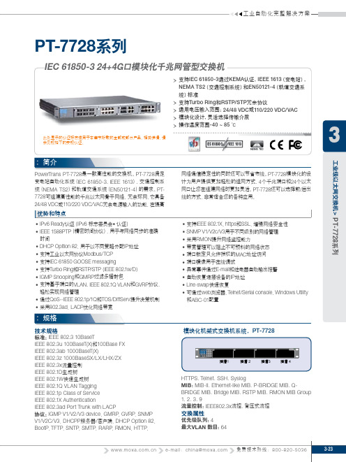
特点∙支持IEC 61850-3,IEEE 1613 (变电站),NEMA TS2 (交通控制系统),和 EN50121-4(轨道应用) 标准。
∙支持IEEE 1588 PTP,用于网络精密时间同步。
∙支持用于以太网冗余的Turbo Ring,Turbo Chain 和 IEEE 802.1D-2004 RSTP/STP 。
∙配备独立冗余电源输入以适应24/48 VDC或110/220 VDC/VAC 工作电压范围。
∙为多种媒体选项而作的模块化设计。
∙-40~85℃的工作温度。
MOXA 机架式全网管工业以太网交换机PT-7728-S-24T 全网管型机架式工业交换机,24个10/100M固定电口,后面板出线、前面板LED显示,支持一路电源110/220 VDC/VAC输入,可配PM7200的1光/2光模块PT-7728-S-HV 全网管机架式模块化百兆工业交换机,带8个10/100M RJ45口,另提供2个用于安装100M光模块的插槽,可配置PM7200百兆多口模块,后面板出线、前面板LED 显示,支持一路电源110/220 VDC/VAC输入PT-7728-R-HV 机架式模块化网管型交换机系统,配备3个用于安装100M模块的插槽和1个用于安装1000M模块的插槽,最高可配置24+4G个端口,后面板出线、前面板LED显示,支持一路电源110/220 VDC/VAC输入PT-7728-R-HV-HV 机架式模块化网管型交换机系统,配备3个用于安装100M模块的插槽和1个用于安装1000M模块的插槽,最高可配置24+4G个端口,后面板出线、前面板LED 显示,支持两路电源110/220 VDC/VAC冗余输入PT-7728-R-24 机架式模块化网管型交换机系统,配备3个用于安装100M模块的插槽和1个用于安装1000M模块的插槽,最高可配置24+4G个端口,后面板出线、前面板LED显示,支持一路电源24VDC输入PT-7728-R-24-24 机架式模块化网管型交换机系统,配备3个用于安装100M模块的插槽和1个用于安装1000M模块的插槽,最高可配置24+4G个端口,后面板出线、前面板LED显示,支持两路电源24VDC冗余输入PT-7728-R-24-48 机架式模块化网管型交换机系统,配备3个用于安装100M模块的插槽和1个用于安装1000M模块的插槽,最高可配置24+4G个端口,后面板出线、前面板LED显示,支持两路电源24VDC和48VDC冗余输入PT-7728-R-24-HV 机架式模块化网管型交换机系统,配备3个用于安装100M模块的插槽和1个用于安装1000M模块的插槽,最高可配置24+4G个端口,后面板出线、前面板LED显示,支持两路电源24VDC和110/220 VDC/VAC冗余输入PT-7728-R-48 机架式模块化网管型交换机系统,配备3个用于安装100M模块的插槽和1个用于安装1000M模块的插槽,最高可配置24+4G个端口,后面板出线、前面板LED显示,支持一路电源48VDC输入PT-7728-R-48-48 机架式模块化网管型交换机系统,配备3个用于安装100M模块的插槽和1个用于安装1000M模块的插槽,最高可配置24+4G个端口,后面板出线、前面板LED显示,支持两路电源48VDC冗余输入PT-7728-R-48-HV 机架式模块化网管型交换机系统,配备3个用于安装100M模块的插槽和1个用于安装1000M模块的插槽,最高可配置24+4G个端口,后面板出线、前面板LED显示,支持两路电源48VDC和110/220 VDC/VAC冗余输入PT-7828-R-24 IEC 61850、三层机架式模块化网管型交换机系统,配备3个用于安装100M 模块的插槽和1个用于安装1000M模块的插槽,最高可配置24+4G个端口,后面板出线,支持一路隔离电源24VDC输入,-40到85度。
PT-7828-R-24-24 IEC 61850、三层机架式模块化网管型交换机系统,配备3个用于安装100M 模块的插槽和1个用于安装1000M模块的插槽,最高可配置24+4G个端口,后面板出线,支持两路隔离电源24VDC冗余输入,-40到85度。
PT-7828-R-24-48 IEC 61850、三层机架式模块化网管型交换机系统,配备3个用于安装100M 模块的插槽和1个用于安装1000M模块的插槽,最高可配置24+4G个端口,后面板出线,支持两路隔离电源24VDC和48VDC冗余输入,-40到85度。
PT-7828-R-24-HV IEC 61850、三层机架式模块化网管型交换机系统,配备3个用于安装100M 模块的插槽和1个用于安装1000M模块的插槽,最高可配置24+4G个端口,后面板出线,支持两路隔离电源24VDC和110/220 VDC/VAC冗余输入,-40到85度。
PT-7828-R-48 IEC 61850、三层机架式模块化网管型交换机系统,配备3个用于安装100M 模块的插槽和1个用于安装1000M模块的插槽,最高可配置24+4G个端口,后面板出线,支持一路隔离电源48VDC输入,-40到85度。
PT-7828-R-48-48 IEC 61850、三层机架式模块化网管型交换机系统,配备3个用于安装100M 模块的插槽和1个用于安装1000M模块的插槽,最高可配置24+4G个端口,后面板出线,支持两路隔离电源48VDC冗余输入,-40到85度。
PT-7828-R-48-HV IEC 61850、三层机架式模块化网管型交换机系统,配备3个用于安装100M 模块的插槽和1个用于安装1000M模块的插槽,最高可配置24+4G个端口,后面板出线,支持两路隔离电源48VDC和110/220 VDC/VAC冗余输入,-40到85度。
PT-7828-R-HV IEC 61850、三层机架式模块化网管型交换机系统,配备3个用于安装100M 模块的插槽和1个用于安装1000M模块的插槽,最高可配置24+4G个端口,后面板出线,支持一路隔离电源110/220 VDC/VAC冗余输入,-40到85度。
PT-7828-R-HV-HV IEC 61850、三层机架式模块化网管型交换机系统,配备3个用于安装100M模块的插槽和1个用于安装1000M模块的插槽,最高可配置24+4G个端口,后面板出线,支持两路隔离电源110/220 VDC/VAC冗余输入,-40到85度。