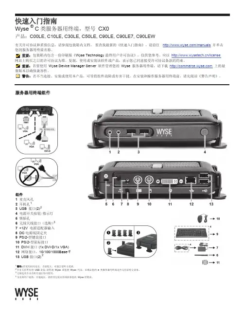
Wyse T系列终端产品介绍
- 格式:pptx
- 大小:1.66 MB
- 文档页数:18


网思技术(北京)有限公司Wyse WTOS 瘦客户机使用简介 基于Wyse ThinOS ™系统July, 2009网思技术(北京)有限公司Table of Contents01【配置Wyse FTP 地址】 (3)02【连接Citrix XenDesktop 虚拟机】 (4)03【重启或关闭】 (7)04【建立并使用RDP 远程连接】 (8)05【切换远程连接】 (11)06【进阶使用】 (12)网思技术(北京)有限公司01【配置Wyse FTP 地址】注:以下步骤只需在第一次使用设备时配置1. 点击开始菜单 > 系统设置 > 网络网思技术(北京)有限公司2. 点击“服务器”标签,在“文件服务器/路径”一栏填写Wyse FTP 地址(请联系管理员获取此地址)3. 点击OK 保存设置,并重启02【连接Citrix XenDesktop 虚拟机】网思技术(北京)有限公司1. 启动机器后,用户输入正确的用户名和密码,并点击确定2. 成功通过验证后,点击桌面的右下角的连接图标,并在列表中选择需要连接的虚拟机3. 使用完虚拟机后,在开始菜单点击“断开”或“注销”。
也可以长按设备外壳上的电源按钮关机(不会影响虚拟机的运行状态)网思技术(北京)有限公司网思技术(北京)有限公司03【重启或关闭】1. 点击开始 > 关机2. 选择“关闭系统”或“关闭并重新启动系统”从而关闭或重启网思技术(北京)有限公司04【建立并使用RDP 远程连接】1. 打开“连接管理器”,点击“新建”,并选择“RDP ”协议2. 第一栏和第二栏信息必填,其他栏目信息可选第一栏:连接描述第二栏:远程服务器或虚拟机的地址(可使用IP 地址或机器名或FQDN )网思技术(北京)有限公司网思技术(北京)有限公司3. 点击OK 保存设置网思技术(北京)有限公司4. 在“连接管理器”界面选需要使用的连接项目,点击“连接”进行连接05【切换远程连接】1. 同时按住Ctrl + Alt + Up (向上方向键),即可将远程连接由全屏状态切换到Window 状态2. 同时按住Ctrl + Alt + Down (向下方向键),即可在远程连接进程间切换(类似于Windows 系统的Alt + Tab 功能)网思技术(北京)有限公司06【进阶使用】更详细的使用说明请见《Wyse Thin OS 用户手册》。

Dell Wyse 5070 Extended 擴充式精簡型用戶端使用者指南2021 8註、警示與警告:「註」表示可以幫助您更有效地使用產品的重要資訊。
:「警示」表示有可能會損壞硬體或導致資料遺失,並告訴您如何避免發生此類問題。
:「警告」表示可能的財產損失、人身傷害或死亡。
© 2018-2021 Dell Inc. 或其子公司。
版權所有,翻印必究。
Dell、EMC 與其他商標均為 Dell Inc.或其子公司的商標。
其他商標可能為其各自擁有者的商標。
章1: 歡迎使用 Dell Wyse 5070 擴充式精簡型用戶端 (6)章2: 機箱概觀 (7)章3: 精簡型用戶端的主要元件 (9)章4: Wyse 5070 精簡型用戶端支援的系統周邊裝置 (10)支援的顯示器 (10)支援的托架 (10)支援的系統周邊裝置 (11)章5: 設定精簡型用戶端 (12)章6: 處理您的精簡型用戶端之前 (16)章7: 處理您的精簡型用戶端之後 (17)章8: 卸下和安裝元件 (18)安全說明 (18)處理您的精簡型用戶端之前 (19)安全預防措施 (19)靜電放電──ESD 保護 (19)ESD 現場維修套件 (20)運送敏感元件 (20)處理您的精簡型用戶端之後 (21)建議的工具 (21)螺絲大小清單 (21)機箱蓋 (22)卸下機箱蓋 (23)安裝機箱蓋 (25)PCIe 模組 (28)卸下 PCIe 模組 (28)安裝 PCIe 模組 (30)幣式電池 (32)卸下幣式電池 (32)安裝幣式電池 (33)固態硬碟 (33)卸下固態硬碟 (34)安裝固態硬碟 (35)擴充模組 (35)卸下擴充模組-VGA-RJ45-SFP (35)安裝擴充模組 - VGA-RJ45-SFP (37)無線網卡 (38)卸下無線網卡 (38)目錄3安裝無線網卡 (39)CAC 讀卡機 (39)卸下 CAC 讀卡機 (39)安裝 CAC 讀卡機 (42)記憶體 (44)卸下記憶體模組 (44)安裝記憶體模組 (48)喇叭和電源按鈕 (49)卸下喇叭和電源按鈕 (49)安裝喇叭和電源按鈕 (51)序列埠與平行埠 (52)卸下序列埠與平行埠 (52)安裝序列埠與平行埠 (54)散熱器 (54)卸下散熱器 (55)安裝散熱器 (56)主機板 (57)卸下主機板 (58)安裝主機板 (60)章9: 技術規格 (61)系統規格 (61)處理器 (61)作業系統 (62)記憶體規格 (62)儲存 (62)音效規格 (63)通訊規格 (63)連接埠和連接器規格 (64)安全保護 (64)電池規格 (64)交流電變壓器規格 (64)實體規格 (65)環境 (65)章10: ThinOS 上的 Wyse 5070 精簡型用戶端組態 (66)簡介 (66)使用「初次開機精靈」設定 ThinOS (66)登入執行 Wyse ThinOS 的 Wyse 5070 精簡型用戶端 (68)本機設定功能表 (68)進行鍵盤設定 (68)進行滑鼠設定 (69)進行顯示設定 (69)進行 LPD 設定 (70)進行印表機設定 (70)進行連接埠設定 (70)進行 LPD 設定 (71)進行 SMB 設定 (71)使用印表機設定選項 (72)4目錄章11: ThinLinux 的 Wyse 5070 精簡型用戶端 (73)簡介 (73)登入執行 ThinLinux 的 Wyse 5070 精簡型用戶端 (73)進行 Wyse ThinLinux 的週邊裝置設定 (73)設定 Dell Wyse ThinLinux 的顯示畫面 (73)進行鍵盤偏好設定 (74)自訂顯示器 (75)進行滑鼠偏好設定 (76)進行印表機設定 (77)章12: Windows 10 IoT Enterprise 的 Wyse 5070 精簡型用戶端 (79)簡介 (79)設定您的精簡型用戶端之前 (79)自動與手動登入 (79)啟用自動登入 (80)鍵盤和地區設定 (80)裝置和印表機 (80)新增印表機 (81)設定多螢幕顯示 (81)章13: BIOS 概觀 (82)存取精簡型用戶端 BIOS 設定 (82)系統設定概觀 (82)開機順序 (83)導覽鍵 (83)General (一般) 畫面選項 (83)System Configuration (系統組態) 畫面選項 (84)Video (影像) 畫面選項 (86)Security (安全性) 畫面選項 (86)Secure Boot (安全開機) 畫面選項 (87)Performance (效能) 畫面選項 (88)Power Management(磁碟管理)畫面選項 (88)POST Behavior(POST 行為)畫面選項 (89)Wireless (無線) 畫面選項 (90)Virtualization Support (虛擬支援) 畫面選項 (90)Maintenance (維護) 畫面選項 (90)「System Log」(系統記錄) 畫面選項 (91)章14: 故障排除您的系統 (92)電源狀態和 LED 狀態 (92)電源行為 (92)電源 LED 錯誤代碼行為 (93)目錄5歡迎使用 Dell Wyse 5070 擴充式精簡型用戶端Wyse 5070 擴充式精簡型用戶端為一款搭載四核心處理器的高效能精簡型用戶端,專為安全而設計,且具備易於管理的虛擬桌面環境。
Dell Wyse 5070 扩展瘦客户端用户指南2021 8注意、小心和警告:“注意”表示帮助您更好地使用该产品的重要信息。
:“小心”表示可能会损坏硬件或导致数据丢失,并告诉您如何避免此类问题。
:“警告”表示可能会导致财产损失、人身伤害甚至死亡。
© 2018-2021 Dell Inc. 或其子公司。
保留所有权利。
Dell、EMC 和其他商标是 Dell Inc. 或其附属机构的商标。
其他商标可能是其各自所有者的商标。
章 1: 欢迎使用 Dell Wyse 5070 extended thin client (6)章 2: 机箱概览 (7)章 3: 瘦客户端的主要组件 (9)章 4: 支持用于 Wyse 5070 thin client 的系统外围设备 (10)支持的显示器 (10)支持的安装方式 (11)支持的系统外围设备 (11)章 5: 设置瘦客户机 (12)章 6: 处理瘦客户机之前 (16)章 7: 拆装瘦客户机之后 (17)章 8: 卸下和安装组件 (18)安全说明 (18)处理瘦客户机之前 (19)安全防范措施 (19)静电放电 (ESD) 保护 (19)ESD 现场服务套件 (20)运输敏感组件 (20)拆装瘦客户机之后 (21)建议工具 (21)螺钉大小列表 (21)机箱盖 (23)卸下机箱盖 (23)安装机箱盖 (25)PCIe 模块 (28)卸下 PCIe 模块 (28)安装 PCIe 模块 (30)币形电池 (32)卸下币形电池 (32)安装币形电池 (33)固态硬盘 (34)卸下固态硬盘 (34)安装固态硬盘 (35)扩展模块 (35)卸下扩展模块 - VGA-RJ45-SFP (35)安装扩展模块 - VGA-RJ45-SFP (37)无线网卡 (38)卸下无线网卡 (38)目录3安装无线网卡 (39)CAC 读卡器 (39)卸下 CAC 读卡器 (39)安装 CAC 读卡器 (42)内存 (44)卸下内存模块 (44)安装内存模块 (48)扬声器和电源按钮 (49)卸下扬声器和电源按钮 (49)安装扬声器和电源按钮 (51)串行和并行端口 (52)卸下串行和并行端口 (52)安装串行和并行端口 (54)散热器 (55)卸下散热器 (55)安装散热器 (56)系统板 (58)卸下系统板 (58)安装系统主板 (61)章 9: 技术规格 (62)系统规格 (62)处理器 (62)操作系统 (63)内存规格 (63)存储 (63)音频规格 (64)通信规格 (64)端口和连接器规格 (65)安全性 (65)电池规格 (65)交流适配器规格 (66)物理规格 (66)环境 (66)章 10: ThinOS 上的 Wyse 5070 瘦客户机配置 (67)简介 (67)使用首次引导向导配置 ThinOS (67)登录到运行 Wyse ThinOS 的 Wyse 5070 thin client (69)本地设置菜单 (69)配置键盘设置 (69)配置鼠标设置 (70)配置显示屏设置 (70)配置 LPD 设置 (71)配置打印机设置 (71)配置端口设置 (71)配置 LPD 设置 (72)配置 SMB 设置 (72)使用打印机设置选项 (73)4目录章 11: ThinLinux 上的 Wyse 5070 瘦客户机 (74)简介 (74)登录到运行 ThinLinux 的 Wyse 5070 thin client (74)在 Wyse ThinLinux 上配置外围设备设置 (74)在 Dell Wyse ThinLinux 上配置显示屏 (74)设置键盘首选项 (75)自定义显示屏 (76)设置鼠标首选项 (77)配置打印机设置 (78)章 12: Windows 10 IoT Enterprise 上的 Wyse 5070 瘦客户机 (80)简介 (80)配置瘦客户端之前 (80)自动和手动登录 (80)启用自动登录 (81)键盘和区域设置 (81)设备和打印机 (82)添加打印机 (82)配置多显示器显示 (82)章 13: BIOS 概览 (83)访问瘦客户机 BIOS 设置 (83)系统设置程序概览 (83)引导顺序 (84)导航键 (84)常规屏幕选项 (84)系统配置屏幕选项 (85)视频屏幕选项 (87)安全性屏幕选项 (87)安全引导屏幕选项 (88)性能屏幕选项 (89)电源管理屏幕选项 (89)POST 行为屏幕选项 (90)无线屏幕选项 (91)虚拟化支持屏幕选项 (91)维护屏幕选项 (91)系统日志屏幕选项 (92)章 14: 系统故障排除 (93)电源状态和LED 指示灯状态 (93)电源行为 (93)电源 LED 错误代码行为 (94)目录5欢迎使用 Dell Wyse 5070 extended thin client Wyse 5070 extended thin client 是采用四核处理器的高性能瘦客户机,其设计可带来安全且易于管理的虚拟桌面环境。
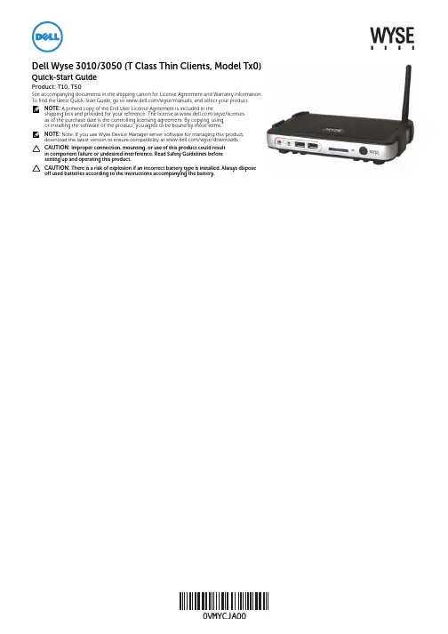
Dell Wyse 3010/3050 (T Class Thin Clients, Model Tx0)Quick-Start GuideProduct: T10, T50See accompanying documents in the shipping carton for License Agreement and Warranty information. To find the latest Quick-Start Guide, go to /wyse/manuals, and select your product.NOTE:A printed copy of the End User License Agreement is included in theshipping box and provided for your reference. The license at /wyse/licensesas of the purchase date is the controlling licensing agreement. By copying, using,or installing the software or the product, you agree to be bound by those terms.NOTE:Note: If you use Wyse Device Manager server software for managing this product, download the latest version to ensure compatibility at /wyse/downloads.CAUTION: Improper connection, mounting, or use of this product could resultin component failure or undesired interference. Read Safety Guidelines beforesetting up and operating this product.CAUTION: There is a risk of explosion if an incorrect battery type is installed. Always dispose off used batteries according to the instructions accompanying the battery.T10, T50[1] Warning: Listening to audio at high volume levels for extended durations can damage your hearing.[2] Not all USB devices are supported; check with Wyse or your Wyse representative to find out if a particular device is supported on your thin client.[3] Wireless option not available in all localities.Components1 Microphone in2 Speaker out [1]3 USB 2.0 port (2)[2]4 SD card slot (not available on T10)5 Activity light6 Power on/off button/light7 Wireless antenna port (optional)[3]8 USB 2.0 port (2)[2]9 DVI-I port (1x DVI-D/1x VGA)10 Product information tab11 Network port, 10/100/1000 Base-T12 +12V Power adapter input13 Lock receptacle14 Horizontal stand/VESA mount15PS/2-type mouse port located on keyboardComponents may vary based on model and location.Setting Up Your Thin ClientBe sure you have read Safety Guidelines before setting up and operating this product. Refer to the figures and proceed as follows:1Make sure the monitor and the thin client are turned off and disconnected from AC power. Place the thin client on a desk or use the horizontal stand/bracket for VESA mounting (assemble with user-provided screws).2Make all desired connections (video display and keyboard with mouse are required). Connection to a 10/100/1000 Base-T Ethernet network is required unless an optional WiFi network adapter is used for wireless connection to a network. Additional connections of peripheral devices may be made to the other ports.3Connect the power adapter to the thin client power input before connecting to a 100-240V AC, 50-60 Hz electrical outlet. Wait until the initialization sequence is completed (the activity light will go off), and then press the power button on the thin client to apply power.Safety GuidelinesImproper connection, mounting, or use of this product could result in component failure or undesired interference. Read the following guidelines before setting up and operating the device.Setup•Do not connect to AC power until all other connections (including the power adapter) are made. Connecting or disconnecting components or equipment on the back panel when the device is receiving AC power can cause power surges and damage the device.•Do not force a connector into its socket. If any undue resistance is encountered, ensure that the connector is correctly oriented to the receptacle.•For wireless usage and requirements, refer to the regulatory notices in the device’s documentation.Venting and Care•Mount the device only as shown or in accordance with the instructions provided with Dell Wyse-approved mounting accessory kits. Improper orientation could restrict airflow of heat from the device and damage it.•Allow sufficient space around the device for ventilation; do not place the device in any enclosure that restricts airflow around the device; do not place any objects on the device or block the vent outlets.For environmental operating specifications, locate your product and download the Fact Sheet using the Cloud clients tab at /wyse/T10.Power Sources•For regulatory compliance use only the power adapter that comes with your device or a Wyse-approved equivalent. For proper replacement compare the labels on both device and power adapter to ensure that their voltages match.WARNING: Use of any other power adapter may damageyour device or the power adapter. The damage caused by an improper power adapter is not covered by warranty.•Accidental loss of power can damage the device. Avoidconnecting it to any power outlet which can be accidentally switched off. Do not hard reset the device by holding down the power button during normal operation.•When turning off the device, be sure to perform a complete shutdown (via the user interface or a light press on the power button). Do not disconnect the AC power cord, DC power cord, or shut off power at a circuit breaker (including power strips), etc., to turn off the device.•Surge protectors for electrical devices are recommended in areas of lightning. However, when lightning is occurring, your equipment should be properly shut down and unplugged from AC power until the storm has passed.•Be very careful to not interrupt power while the device is downloading a software update.Battery The device contains an internal button cell battery replaceable by Dell Wyse or one of our Authorized Service Centers. For service, visit /support/. WARNING: There is a risk of explosion if the battery is replaced by an incorrect type. Always dispose of used batteries according to the instructions accompanying the battery. WARNING: Perchlorate Materials - Special Handling May Be Required under California Code of Regulations, title 22. (Only required within the USA.)Need more information?Dell Reference Guides - Documentation is available at: /wyse/manuals Dell Support - Latest software images are available at: /wyse/downloads Dell Device Manager - Information about Wyse remote management software is available at: /wyse/WDM Dell WSM - Information about Dell WSM software is available at: /wyse/WSM Dell and the Environment - Information about Wyse compliance with RoHS and with the Waste Electrical and Electronic Equipment (WEEE) is available at: /environment Dell and Recycling - Information about recycling unwanted Dell product within the United States is available at: /recycling Dell Warranty - The standard warranty is three years from the date of purchase.____________________________________________________________________Copyright © 2014 Dell Inc. All rights reserved.This product is protected by U.S. and international copyright and intellectual property laws. Dell and the Dell logo are trademarks of Dell Inc. in the United States and/or other jurisdictions. All other marks and names mentioned herein may be trademarks of their respective companies.Sept 2014 Dell PN: VMYCJ Rev: A00。
Dell Wyse 5470 Thin Client 设置和规格注、小心和警告注: “注”表示帮助您更好地使用该产品的重要信息。
小心: “小心”表示可能会损坏硬件或导致数据丢失,并说明如何避免此类问题。
警告: “警告”表示可能会造成财产损失、人身伤害甚至死亡。
© 2019 Dell Inc. 或其子公司。
保留所有权利。
Dell、EMC 和其他商标是 Dell Inc. 或其附属机构的商标。
其他商标可能是其各自所有者的商标。
2019 - 08Rev. A001 设置您的 Wyse 5470 Thin Client (4)2 机箱概览 (5)显示器视图 (5)左侧视图 (7)右侧视图 (7)掌垫视图 (8)底部视图 (9)键盘快捷方式 (9)3 技术规格 (11)芯片组 (11)处理器 (11)内存 (11)端口和接口 (12)智能卡读取器 (12)存储 (12)物理规格 (13)操作系统 (13)通信 (13)以太网 (13)无线模块 (14)音频 (14)介质卡读取器 (14)键盘 (15)摄像头 (15)触摸板 (16)电源适配器 (16)电池 (16)显示器 (17)视频 (18)环境规格 (18)安全性 (19)管理软件 (19)安全软件 (19)4 软件 (20)下载驱动程序 (20)5 获取帮助 (21)联系戴尔 (21)目录3设置您的 Wyse 5470 Thin Client注: 根据您所订购的配置,本文档中的图像可能与您的瘦客户机有所差异。
1 连接电源适配器,然后按下电源按钮。
注: 为节省电池电量,电池可能进入省电模式。
连接电源适配器并按下电源按钮以开启瘦客户机。
2 完成操作系统设置。
4设置您的 Wyse 5470 Thin Client机箱概览显示器视图Wyse 5470(带非触摸屏)1摄像头2摄像头状态指示灯3麦克风4LCD 面板5通用访问读卡器 - 可选Wyse 5470 with touch screen (optional)机箱概览51Microphone2Camera3Camera status light4LCD panel5Common Access Card reader—optional6机箱概览1电源输入(4.5 毫米适配器)2电池状态指示灯3USB T ype-C 3.1 Gen 1 端口,具有电源传输和 DisplayPort 功能4HDMI 2.0a 端口5RJ45 端口6USB 3.1 Gen 1 端口7USB 3.1 Gen 1 端口8通用音频插孔右侧视图1SD 3.0 内存卡读取器2USB 2.0 端口(带 PowerShare)3VGA 端口4Nobel 楔形钥匙锁锁槽机箱概览71电源按钮2键盘3触摸板8机箱概览1散热器通风口2服务标签3扬声器键盘快捷方式表. 1: 键盘快捷方式机箱概览910机箱概览技术规格芯片组表. 2: 芯片组处理器表. 3: 处理器内存表. 4: Memoryspecifications 3技术规格11端口和接口表. 5: 端口和接口智能卡读取器表. 6: 通用访问读卡器—可选存储瘦客户机支持以下配置之一:•M.2 2230 固态驱动器•M.2 2280 固态驱动器•eMMC 存储(焊接在系统板上)12技术规格表. 7: 存储规范注:如果您的系统随附 M.2 SSD ,则 M.2 SSD 默认为主驱动器。

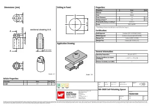
Dimensions: [mm]sectional drawing A-AAAScale- 4:1702941500Cautions and Warnings:The following conditions apply to all goods within the product series of WA-SNSR ofWürth Elektronik eiSos GmbH & Co. KG:General:•This mechanical component is designed and manufactured for use in general electronic equipment.•Würth Elektronik must be asked for written approval (following the PPAP procedure) before incorporating the components into any equipment in fields such as military, aerospace, aviation, nuclear control, submarine, transportation (automotive control, train control, ship control), transportation signal, disaster prevention, medical, public information network, etc. where higher safety and reliability are especially required and/or if there is the possibility of direct damage or human injury.•Mechanical components that will be used in safety-critical or high-reliability applications, should be pre-evaluated by the customer. •The component is designed and manufactured to be used within the datasheet specified values. If the usage and operation conditions specified in the datasheet are not met, the component may be damaged or dissolved.•Do not drop or impact the components, the component may be damaged.•Würth Elektronik products are qualified according to international standards, which are listed in each product reliability report. Würth Elektronik does not warrant any customer qualified product characteristics beyond Würth Elektroniks’ specifications, for its validity and sustainability over time.•The responsibility for the function of the application of the customer specific products and use in a particular customer design is always the full and autonomous responsibility of the customer. All technical specification for standard products also apply to customer specific products.Product Specific:Cleaning and Washing:•Washing agents used during the production to clean the customer application might damage or change the characteristics of the components. Washing agents may have a negative effect on the long-term functionality of the product.•Using a brush during the cleaning process may damage the component. Therefore, we do not recommend using a brush during the PCB cleaning process.Potting and Coating:•If the product is potted in the customer application, the potting material might shrink or expand during and after hardening. Shrinking could lead to an incomplete seal, allowing contaminants into the components. Expansion could damage the components. Werecommend a manual inspection after potting or coating to avoid these effects. Storage Conditions:• A storage of Würth Elektronik products for longer than 12 months is not recommended. Within other effects, the terminals may suffer degradation, resulting in bad processability. Therefore, all products shall be used within the period of 12 months based on the day of shipment.•Do not expose the components to direct sunlight.•The storage conditions in the original packaging are defined according to DIN EN 61760-2.•The storage conditions stated in the original packaging apply to the storage time and not to the transportation time of the components. Packaging:•The packaging specifications apply only to purchase orders comprising whole packaging units. If the ordered quantity exceeds or is lower than the specified packaging unit, packaging in accordance with the packaging specifications cannot be ensured. Handling:•The maximum permissible torques must be complied with to prevent mechanical destruction of the component and PCB.•If a component is pre-assembled with an adhesive tape, the adhesive duration cannot be guaranteed. This depends on the surface where the component will be mounted on. It also depends on the environmental conditions the component is exposed to. The customer has to evaluate this for his specific application.•Violation of the technical product specifications will void the warranty.•Coated metal parts may have spots and/or deposits because of the rinsing and drying process during plating. The storage and processability are not affected.•The temperature rise of the component must be taken into consideration. The operating temperature is comprised of ambient temperature and temperature rise of the component.The operating temperature of the component shall not exceed the maximum temperature specified.These cautions and warnings comply with the state of the scientific and technical knowledge and are believed to be accurate and reliable.However, no responsibility is assumed for inaccuracies or incompleteness.Würth Elektronik eiSos GmbH & Co. KGEMC & Inductive SolutionsMax-Eyth-Str. 174638 WaldenburgGermanyCHECKED REVISION DATE (YYYY-MM-DD)GENERAL TOLERANCE PROJECTIONMETHODJSa001.0012021-11-17DIN ISO 2768-1mDESCRIPTIONWA-SNSR Self-Retaining SpacerORDER CODE702941500BUSINESS UNIT STATUS PAGEImportant NotesThe following conditions apply to all goods within the product range of Würth Elektronik eiSos GmbH & Co. KG:1. General Customer ResponsibilitySome goods within the product range of Würth Elektronik eiSos GmbH & Co. KG contain statements regarding general suitability for certain application areas. These statements about suitability are based on our knowledge and experience of typical requirements concerning the areas, serve as general guidance and cannot be estimated as binding statements about the suitability for a customer application. The responsibility for the applicability and use in a particular customer design is always solely within the authority of the customer. Due to this fact it is up to the customer to evaluate, where appropriate to investigate and decide whether the device with the specific product characteristics described in the product specification is valid and suitable for the respective customer application or not.2. Customer Responsibility related to Specific, in particular Safety-Relevant ApplicationsIt has to be clearly pointed out that the possibility of a malfunction of electronic components or failure before the end of the usual lifetime cannot be completely eliminated in the current state of the art, even if the products are operated within the range of the specifications.In certain customer applications requiring a very high level of safety and especially in customer applications in which the malfunction or failure of an electronic component could endanger human life or health it must be ensured by most advanced technological aid of suitable design of the customer application that no injury or damage is caused to third parties in the event of malfunction or failure of an electronic component. Therefore, customer is cautioned to verify that data sheets are current before placing orders. The current data sheets can be downloaded at .3. Best Care and AttentionAny product-specific notes, cautions and warnings must be strictly observed. Any disregard will result in the loss of warranty.4. Customer Support for Product SpecificationsSome products within the product range may contain substances which are subject to restrictions in certain jurisdictions in order to serve specific technical requirements. Necessary information is available on request. In this case the field sales engineer or the internal sales person in charge should be contacted who will be happy to support in this matter.5. Product R&DDue to constant product improvement product specifications may change from time to time. As a standard reporting procedure of the Product Change Notification (PCN) according to the JEDEC-Standard inform about minor and major changes. In case of further queries regarding the PCN, the field sales engineer or the internal sales person in charge should be contacted. The basic responsibility of the customer as per Section 1 and 2 remains unaffected.6. Product Life CycleDue to technical progress and economical evaluation we also reserve the right to discontinue production and delivery of products. As a standard reporting procedure of the Product Termination Notification (PTN) according to the JEDEC-Standard we will inform at an early stage about inevitable product discontinuance. According to this we cannot guarantee that all products within our product range will always be available. Therefore it needs to be verified with the field sales engineer or the internal sales person in charge about the current product availability expectancy before or when the product for application design-in disposal is considered. The approach named above does not apply in the case of individual agreements deviating from the foregoing for customer-specific products.7. Property RightsAll the rights for contractual products produced by Würth Elektronik eiSos GmbH & Co. KG on the basis of ideas, development contracts as well as models or templates that are subject to copyright, patent or commercial protection supplied to the customer will remain with Würth Elektronik eiSos GmbH & Co. KG. Würth Elektronik eiSos GmbH & Co. KG does not warrant or represent that any license, either expressed or implied, is granted under any patent right, copyright, mask work right, or other intellectual property right relating to any combination, application, or process in which Würth Elektronik eiSos GmbH & Co. KG components or services are used.8. General Terms and ConditionsUnless otherwise agreed in individual contracts, all orders are subject to the current version of the “General Terms and Conditions of Würth Elektronik eiSos Group”, last version available at .Würth Elektronik eiSos GmbH & Co. KGEMC & Inductive SolutionsMax-Eyth-Str. 174638 WaldenburgGermanyCHECKED REVISION DATE (YYYY-MM-DD)GENERAL TOLERANCE PROJECTIONMETHODJSa001.0012021-11-17DIN ISO 2768-1mDESCRIPTIONWA-SNSR Self-Retaining SpacerORDER CODE702941500BUSINESS UNIT STATUS PAGE。
QUICK CARDEthernet RFC 2544 Layer 2 TrafficThis quick card describes how to configure and run an RFC 2544 Layer 2 Traffic Test for Metro Ethernet service activation.•T-BERD/MTS 5800 equipped with the following:o BERT software release V30.1.0 or greatero C510M1GE test option for 10 Megabit to 1 Gigabit Etherneto C510GELAN test option for 10 Gigabit Etherneto C525GE test option for 25 Gigabit Etherneto C540GE test option for 40 Gigabit Etherneto C550GE test option for 50 Gigabit Etherneto C5100GE test option for 100 Gigabit Ethernet•Optical Transceiver supporting the line rate to be tested(SFP or QSFP)•Cables to match the optical transceiver and the line under test•Fiber optic inspection microscope (P5000i or FiberChek Probe)•Fiber optic cleaning supplies Figure 1: Equipment Requirements1.Press the Power button to turn on theT-BERD.2.Press the Test icon at the top of thescreen to display the Launch Screen.ing the Select Test menu, Quick Launchmenu, or Job Manager, launch the EthernetRFC 2544 Layer 2 Traffic test on Port 1 for the desired rate. For Example:Ethernet►1GigE Optical ►RFC 2544 ►L2 Traffic ►P1 Terminate.4.Tap the button next to “Start a NewConfiguration (reset to defaults)”Figure 2: Launch ScreenQUICK CARD►The following Information is needed to configure the test:•VLAN ID, if VLAN tagging is used.•Maximum Transmission Unit (MTU), if Jumbo Frames are used.•Committed Information Rate (CIR)•Pass/Fail Threshold for Throughput, Frame Loss, Latency and Jitter1.Tap the button to display theL2 Network Settings screen.2.If you are testing a VLAN, setEncapsulation to VLAN and enter yourVLAN ID.3.Tap the button twice to displaythe Select Tests screen.4.Select the Throughput, Latency, FrameLoss, and Packet Jitter tests.5.Tap the button to display theUtilization screen.6.Set Max Bandwidth to the CommittedInformation Rate (CIR).7.Tap the button to display theFrame Lengths screen.Figure 4: Work OrderFigure 6: Select TestsFigure 5: L2 Network SettingsQUICK CARD8.Select the 1st, 4th, and 8th Frame Lengths.9.If the MTU is greater than 1518 (1522 with VLAN tagging), also enter and select the frame length of the MTU.10.Deselect (uncheck) all other frame lengths.11.Tap the button four times to display the Test Thresholds screen.12.Check all boxes for which a Pass/Fail Threshold is known. Enter the Threshold for each selection.13.Tap the button 3 times to display theRun J-QuickCheck screen.Figure 8: Frame LengthsFigure 9: Test ThresholdsFigure 10: J-QuickCheckQUICK CARD►For Optical Interfaces:e the VIAVI P5000i or FiberChek Probemicroscope to inspect both sides of everyconnection being used (SFP, attenuators,patch cables, bulkheads)o Focus the fiber on the screen.o If it appears dirty, clean the fiber end-face and re-inspect.o If it appears clean, run the inspection test.o If it fails, clean the fiber and re-runinspection test. Repeat until it passes.2.Insert desired Optical Transceiver into thePort 1 SFP or QSFP slot on the top of theT-BERD.3.If necessary, insert optical attenuators intothe SFP TX and/or RX ports.4.Connect the SFP to the port under testusing a jumper cable compatible with theline under test.►For Copper 10/100/1000BASE-T interfaces: Connect the 10/100/1000 RJ-45 jack tothe port under test using CAT 5E or bettercable.►Verify that Local Port status UP and Full Duplex (FD)►Tap the button.►Verify that the Remote Loop is recognized, and that Measured Throughput is greater than or equal to the Committed Information Rate.►Tap the button to display the Run RFC 2544Tests screen. Figure 12: Local Port statusFigure 11: Inspect Before You Connect Figure 13: Run J-QuickCheckQUICK CARD© 2022 VIAVI Solutions, Inc,Product specifications and descriptions in this Contact Us+1 844 GO VIAVI(+1 844 468-4284)1.Tap the button three times to display the Report screen.2.Tap .3.Tap buttons three times toclose the report and exit the RFC 2544 test.1.Tap the button.2.Wait for the test to complete and verify that all tests pass or complete as indicated by agreen or blue checkmark.E RE P ORTFigure 14: Run RFC 2544 TestsFigure 15: Create ReportFigure 16: Exit。
5060Install the stand安裝腳架Pasang penyanggaلماحلا بيكرت1Connect the keyboard and mouse連接鍵盤與滑鼠Menyambungkan keyboard dan mouseسواملاو حيتافملا ةحول ليصوتب مق2Connect the power cable andpress the power button連接電源線然後按下電源按鈕Sambungkan adaptor daya dan tekan tombol daya.ليغشتلا رز ىلع طغضاو رايتلا لباك ليصوتب مق5Connect the display andpress the power button連接顯示器,然後按下電源按鈕Sambungkan adaptor daya dan tekan tombol daya.ليغشتلا رز ىلع طغضاو ةشاشلا ليصوتب مق4Connect the network interface連接網路介面Sambungkan ke antarmuka jaringanةكبشلا ةهجاو ليصوتب مق3o remove the SFP interface, rotate the latch and unplug it from its slot.若要卸下 SFP介面,請轉動閂鎖,然後將其從插槽拔下。
Untuk melepaskan Antarmuka SFP, putar kait dan lepaskan dari slotnya..هتحتف نم هلصفو جالزملا ريودتب مق ،SFP ةهجاو ةلازلإ :ةظحلامRJ-45 interfaceRJ-45 介面Antarmuka RJ-45RJ-45 ةهجاوOr | 或 | Atau | وأSFP InterfaceSFP介面Antarmuka SFPSFP ةهجاوFeatures功能 | Fitur-Fitur |تازيملا1. Power button/Power light2. Activity light3. USB 2.0 port (2)4. Headset port5. Wireless antenna port (optional)6. Product information tag7. +19V Power port8. Security-cable slot9. Wireless antenna port (optional)10. DisplayPort 11. DisplayPort 12. USB 2.0 port (2)13. USB 3.1 Gen 1 port (2)14. Network port, 10/100/1000 Base-Tinterface (optional)15. SFP interface (optional)1. 電源按鈕/電源指示燈2. 活動指示燈3. USB 2.0 連接埠 (2 個)4. 耳麥連接埠5. 無線天線連接埠 (可選)6. 產品資訊標籤7. +19V 電源連接埠8. 安全纜線孔9. 無線天線連接埠 (可選)10. DisplayPort 11. DisplayPort12. USB 2.0 連接埠 (2 個)13. USB 3.1 第 1 代連接埠 (2 個)14. 網路連接埠,10/100/1000 Base-T 介面 (選配)15. SFP 介面 (選配)Product support and manuals 產品支援與手冊Manual dan dukungan produkلئلادلاو جتنملا معد/support/support/manualsContact Dell與 Dell 公司聯絡 | Hubungi Dell Dell ـب لاصتلاا/contactdellRegulatory and safety法規與安全規範 | Pengatur dan keamanan ةملاسلاو ةيميظنتلا تاراعشلإا/regulatory_complianceRegulatory model 法規型號 | Model pengatur يميظنتلا زارطلاN07DRegulatory type法規類型 | Tipe pengatur يميظنتلا عونلاN07D001Computer model 電腦型號 | Model komputer رتويبمكلا زارطWyse 5060Wyse 5060 系列1. Tombol daya/Lampu daya2. Lampu aktivitas3. Port USB 2.0 (2)4. Port headset5. Port antena nirkabel (opsional)6. Tag informasi produk7. Port Daya +19V8. Slot kabel pengaman9. Port antena nirkabel (opsional)10. DisplayPort 11. DisplayPort 12. Port USB 2.0 (2)13. Port USB 3.1 Gen 1 (2)14. Port jaringan, antarmuka Base-T10/100/1000 (opsional)15. Antarmuka SFP (opsional)1.ليغشتلا حابصم/ليغشتلا رز2 .طاشنلا حابصم3 .)2( USB 2.0 ذفنم4.سأرلا ةعامس ذفنم5.)يرايتخا( يكلسلالا يئاوهلا ذفنم6 .جتنملا تامولعم ةملاع7.تلوف +19 ةقاط ذفنم8.ناملأا لباك ةحتف9.)يرايتخا( يكلسلالا يئاوهلا ذفنم10 .DisplayPort 11 .DisplayPort 12.)2( USB 2.0 ذفنم13 .)2( لولأا ليجلا نم USB 3.1 ذفنم14. ةهجاوب 10/100/1000 ،ةكبشلا ذفنم )يرايتخا( Base-T15.)يرايتخا( SFP ةهجاو2017-05© 2017 Dell Inc. or its subsidiaries.。
Dell Wyse 5030 PCoIP Zero Client User GuideNotes, cautions, and warningsNOTE: A NOTE indicates important information that helps you make better use of your product.CAUTION: A CAUTION indicates either potential damage to hardware or loss of data and tells you how to avoid the problem.WARNING: A WARNING indicates a potential for property damage, personal injury, or death.© 2017 Dell Inc. or its subsidiaries. All rights reserved. Dell, EMC, and other trademarks are trademarks of Dell Inc. or its subsidiaries. Other trademarks may be trademarks of their respective owners.2017 - 10Rev. A00Welcome to Dell Wyse 5030 PCoIP zero client The Dell Wyse 5030 PCoIP zero client delivers workstation-level performance. It is compact, strong, and flexible. Its dedicated hardware PCoIP engine delivers the highest level of display performance available for advanced applications, including CAD, 3D solids modeling, video editing, and so on.It offers the full benefits of an efficient and secure centralized computing environment, like multiple display support, multimedia playback, HD audio, and four USB peripheral ports.Welcome to Dell Wyse 5030 PCoIP zero client3Hardware installation Dell Wyse 5030 PCoIP zero client hardware installationFor more information about hardware installation, see the Dell Wyse 5030 PCoIP Zero Client Quick Start Guide at Dell Support4Hardware installationInitial environment setup Dell Wyse 5030 zero client uses PC-over- IP (PCoIP) protocol environment. The zero client connects to a host server which is PCoIP capable.Before setting up and using the zero client, you should install PCoIP. This guide helps you to set up the zero client and establish a remote connection to your host server using PCoIP technology.NOTE: PCoIP technology is designed to deliver a user desktop from a centralized host server across standard IP networks. ThePCoIP technology supports full DisplayPort or DVI-D quad monitor video, complete USB 2.0 compatibility, and full-duplex high-definition audio.Initial environment setup5Setting up the zero client Read the Safety Guidelines before setting up and operating the product. Make sure the All-in-One zero client is turned off anddisconnected from the AC power.To set up the zero client, do the following:1 Connect the keyboard, mouse, and Ethernet network.The remaining connections of the peripheral devices are connected to other ports.2 Connect the power cable to the zero client power input port before connecting to a 100-240 V AC, 50 to 60 Hz electrical outlet.3 Press the Power Button and the power button turns green.4 Wait for the monitor to display the On Screen Display (OSD).Zero client LED indicators include:•Off—AC power is off.•Amber—AC power is on, and zero client power is off.•Green—Zero client power is on.•Blinking green—Host server is in low-power state.NOTE: If the monitor does not show the OSD, check the connections and make sure the All-in-One zero client is turnedon.6Setting up the zero clientEstablishing a PCoIP connection To establsih a PCoIP connection, do the following:1 Turn on the zero client and wait until the Connect command button on the zero client user screen is active.2 Click Connect.NOTE: If the Connect command button on the zero client user screen is inactive or if the zero client cannot discoverhost servers on the network, check the network connection and make sure the Ethernet switch or router is turned on.The following message is displayed:Discovering hosts, please wait …After the process of host discovery is complete, a list of available hosts on the network is displayed.3 Select the preferred host, and click OK.Establishing a PCoIP connection7Video resolution How to set custom resolution for PCoIP zero clients PCoIP zero clients enables you to set a custom resolution on the client, which is saved even when the thin client is turned off. This lets you set a resolution that is different from the attached display's native resolution. The following are the steps to set the display resolution:1 Connect to the On-Screen Display (OSD).2 Select Options, and then select User Settings.3 Click Display T opology, and then enable display configuration.4 Select the display resolution from the list of supported resolution values.NOTE:•Zero clients with firmware 3.0 to 3.1.x inherit the native resolution of the attached monitor.•In the View environments, this capability requires a connection to a VMware View 4.5 or newer virtual desktop. Also, make sure the VMware View has enough video RAM set to support high resolutions.Display connectors with PCoIP enabled deviceThe following information describes various display connectors, ports, and how they are used with a focus on achieving resolution of2560x1600:Depending on the PCoIP device, you can have multiple display connectors that have different uses, such as:1DVI-A—analog video only—This DVI-A is used for analog displays using a DVI-VGA adapter cable.2DVI-I—integrated digital and analog video—This DVI-I is used for digital displays with DVI cables or analog displays with a DVI-VGA adapter cable.3DVI-D—digital video only—This can be used for digital displays with DVI cables.4Display Port (DP)—This DVI-D can be used for DisplayPort displays with a DisplayPort cable or DVI displays if a DP-DVI adapter cable is used.Individual Display Port links support dual-link data rates when operating in Display Port mode supporting resolutions of 2560x1600.They can also provide single-link data rates when operating in DisplayPort++/DVI mode.5Mini DisplayPort (mDP)—This Mini DisplayPort can be used for the Mini Display Port displays with a mDP cable, or a mDP-DP cable or DVI displays if a mDP-DVI adapter cable is used.Mini DisplayPort links supports dual-link data rates and 2560x1600 resolutions.6Single-link DVI—SL-DVI—The DVI specification allows a maximum pixel clock of 165 MHz to be used on a single-link DVI video signal. The highest 60Hz-refresh VESA resolution supported by single-link connections is 1920x1200.7Dual-link DVI—DL-DVI—Dual-link DVI doubles the number of data pairs, which allows resolutions requiring an effective pixel clock of up to 330 Hz to be supported. The highest 60 Hz refresh VESA resolution supported by dual-link DVI connections is 2560x1600.NOTE: These dual-link connectors can support either single-link data rates or dual-link data rates.8Video resolutionNOTE:•PCoIP zero clients only supply single-link data rates through each DVI connector.•Dual-link connectors are provided to allow all the digital DVI cable types.•Single-link DVI cables can be plugged into dual-link DVI connectors and passes single link data rates, if the analog pin compatibility is maintained.•Dual-link DVI cables require dual-link DVI connectors and can not be plugged into single-link DVI connectors. Analog pin compatibility is also required.•T o achieve 2560x1600 @ 60 Hz resolutions on a dual-link DVI capable monitor through a PCoIP zero client, you must use an adapter cable to combine two single-link DVI data outputs into a single dual-link DVI connection. Monitor resolutions and refresh rates supported in PCoIP zero clients and host cardsIn general, PCoIP zero clients and the Remote Workstation cards should work with standard display resolutions supported by Video Electronics Standards Association (VESA).The following are the list of tested monitor resolutions supported —display timing, all at 60 Hz display refresh rate:1Single-link rate—•640 x 480•800 x 600•848 x 480•1024 x 768•1280 x 720•1280 x 768•1280 x 800•1280 x 960•1280 x 1024•1360 x 768•1366 x 768•1400 x 1050•1440 x 900•1600 x 900•1600 x 1200•1680 x 1050•1920 x 1080•1920 x 12002Dual-link rate—•1792 x 1344•1856 x 1392•1856 x 1392Video resolution97Safety guidelines Improper connection, or mounting of the product could result in component failure or undesired interference. Follow the below guidelines before setting up and operating your device.•Setup—•Do not connect to AC power until all other connections—including the power adapter are made. Connecting or disconnecting components, or equipment on the back panel when the device is receiving AC power can cause power surges, and damage the device.•Do not force a connector into its socket. If any undue resistance is encountered, ensure that the connector is correctly oriented to the receptacle.•Venting and care—•Mount the device only as shown or in accordance with the instructions provided with Dell approved mounting accessory kits.Improper orientation could restrict the airflow of heat from the device and damage it.•Allow sufficient space around the device for ventilation, do not place the device in any enclosure that restricts airflow around the device, and do not place any objects on the device or block the vent outlets. For environmental operating specifications, seeSystem specifications.•Power sources—•When turning off the device, make sure to perform a complete shutdown—through the power button. Do not disconnect the AC power cord, DC power cord, or shut off power at a circuit breaker—including power strips, to turn off the device.•Surge protectors for electrical devices are recommended in areas of lightning. However, when lightning is occurring, your equipment should be properly shut down and unplugged from AC power until the storm has passed.10Safety guidelines8System specifications This section provides the configuration details of Dell Wyse 5030 zero client.T able 1. System specificationsSystem specifications1112System specifications。
只需四步轻松搞定瘦客户机运维管理只需四步轻松搞定瘦客户机运维管理为用户挑选合适的设备可以为运行在数据中心的桌面带来诸多益处,但首先,你得选对瘦客户机。
在之前的文章中,我们介绍了一些选择瘦客户机的技巧,例如要考虑一致性、内存扩展性等。
实际上,企业真正要用好瘦客户机就必须拥有一套集中管理基础设施,这样才能降低长期运维开销。
第一步:找对管理工具主要的还是你要明白你自己环境中的具体需求,然后看供应商是否有相应工具可用。
如果工具不够灵活或者难以使用,就需要考虑更换终端类型或者供应商了。
一些供应商针对特殊的瘦客户端类型提供了不同的工具。
寻找能够针对瘦客户端应用组策略和进行批量固件升级的工具,理想的情况是在设备启动时自动进行。
如果终端管理工具能够很好地和现有的硬件及资产管理系统协同工作,那就更好了。
例如戴尔Wyse云客户端管理器(Dell Wyse Cloud Client Manager)提供了基于云计算的新的管理方法。
可以在本机及外部实现针对戴尔Wyse瘦客户机与零客户端的基于云的远程配置和管理功能,还可以根据个人或群组成员身份来相应规定终端用户权利和使用权限,以提升效率以及使用户能够主动自我管理,从而显著减轻IT部门的负担。
第二步:前期测试不可少最佳方式是在分支办公室进行管理特性测试。
如果你准备在远程站点中部署瘦客户端设备,那么就需要一种远程办公室员工能够部署的瘦客户机类型。
为了进行测试,将两个瘦客户机设备带到远程办公室,一个保持未拆封状态。
在桌面上部署第一个设备,使其处于工作状态。
然后将包装未拆封的那个交给当地员工,让他将其和部署好的那个进行互换。
这样做的目的是查看当现有的瘦客户端损坏后是否能够直接邮寄一个新的瘦客户端到分支办公室以进行替换。
更为严格的测试是在一个空桌子上,仅仅提供网络连接和电源,而没有可替换的瘦客户端。
理想情况下,新的设备在到达分支办公室前不需要进行任何配置,并且当地IT员工也不需要接受任何培训。