5600 5600SE 中文操作手册
- 格式:pdf
- 大小:174.65 KB
- 文档页数:13
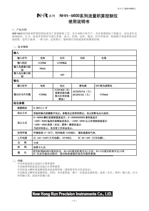

LV5600MUL TI W A VEFORM MONITORLV7600MUL TI W AVEFORM MONITOR概要LV5600/LV7600是支持4K/HD/SD-SDI信号和HD/SD的IP信号的共用选件单元的综合型波形监视器和波形监测仪。
LV5600配有7英寸触摸屏显示器支持AC电源的3U高度半个机架宽度波形监视器。
LV7600是1U高度一个机架宽的与LV5600相同功能的波形监测仪。
根据监看的信号和所需功能选配选件,实现最合理的高效率设备定制。
特点支持多种信号输入可监测及监看最高到12G-SDI为止的各种SDI信号和IP (video over IP)信号。
音频信号支持SDI嵌入式音频、IP 中叠加的音频信号、外部输入的AES/EBU音频、模拟音频。
卓越的操作性一方面沿袭了之前机种的操作键和多功能旋钮的操作配置,同时也可以使用USB鼠标操作。
并且为了进一步提高方便性LV5600采用了触屏功能的7英寸全高清液晶面板;LV7600通过USB线连接触屏式外置LCD,可直观地进行各种触屏操作和设置。
※不保证所有触屏式外置LCD监视器均可运作。
SDI输入信号格式支持SD-SDI,HD-SDI,3G-SDI,12G-SDI单链路、3G-SDI 双链路及4链路、HD-SDI的4链路信号。
IP信号输入格式IP信号支持SMPTE ST 2022-6(非压缩)、SMPTE ST 2022-7、SMPTE 2110-20(非压缩)标准接口的2K视频信号。
2K视频格式时,使用1根10G比特以太网线可接收最多2个通道的信号。
IP信号分析通过IP流状态分析界面可以监看信号源IP地址、目标地址,并且同时对PTP显示相关的时间信息和延时信息。
传输质量分析功能SDI信号分析功能,不仅有各种传输错误的监看、外同步相位差显示、视音频延时测量、SDI信号频率偏差测量功能,而且还实现了4K系统中非常关键的辅助数据深度分析功能。
安装1、安装的一般要求①、进水压力应在0.2-0.5MPa,当水源压力无法满足要求时,可安装增压水泵提高进水压力。
如果压力过高,应安装减压阀来控制进水压力。
②、进水温度应在5-45℃之间,电源采用交流200V/50Hz。
③、软水器应安装在牢固的平台上,附近有畅通的下水,并留有足够的操作和维修空间。
④、工作环境温度应在5-50℃之间,相对湿度≤95%(5℃时)。
2、控制阀的安装与树脂填装(顶装形式)第一步:首先将下布水器牢固安装在中心管底端,然后插入到树脂罐中央,在中心管上端低于罐口0.5mm处截断并导角,然后用胶带封住中心管口,以防树脂漏入。
第二步:将石英砂沿中心管周围空隙投入树脂罐,并使之在罐底铺平,石英砂高于下布水器上20mm,石英砂应按粒径级别分层铺装,主要起到布水作用(对于直径小于500mm树脂罐一般不装石英砂)。
第三步:将树脂均匀地装入树脂罐中,装至规定的层高后,再向注入10%的食盐溶液,至浸没树脂为止,使树脂充分膨胀。
树脂装填完,应取下中心管的封口胶带,上述操作时应注意使中心管始终保持在树脂罐口的中央位置。
第四步:将上布水器安装到控制阀上,然后将中心管从上布水器内插入到控制阀内,小心地沿顺时针方向转动控制阀,直至旋紧在树脂罐接口上(或用法兰连接固定)。
注意上布水器与控制阀、中心管,下布水器与中心管必须严密,防止树脂跑出。
中心管与控制阀必须严密不漏水,否则会出现窜硬水现象。
3、管道连接要求①、与软水器连接的管道应采用给水塑料管,排水管不得采用软塑料管,防止管道变形,影响排水效果。
②、按照控制阀进出水箭头标记连接进出水管,采用流量型再生控制器,流量计必须安装在出水口。
③、进出水管应装有压力表及手动阀门,同时还应装有旁通阀,在出水管阀前还应安装有取样阀。
进水管阀后一般安装有 Y 型过滤器,防止管道内污物堵塞阀体造成设备无法正常运行。
④、排水管的连接长度不应超过6m,尽量减少弯度,并严禁安装阀门。
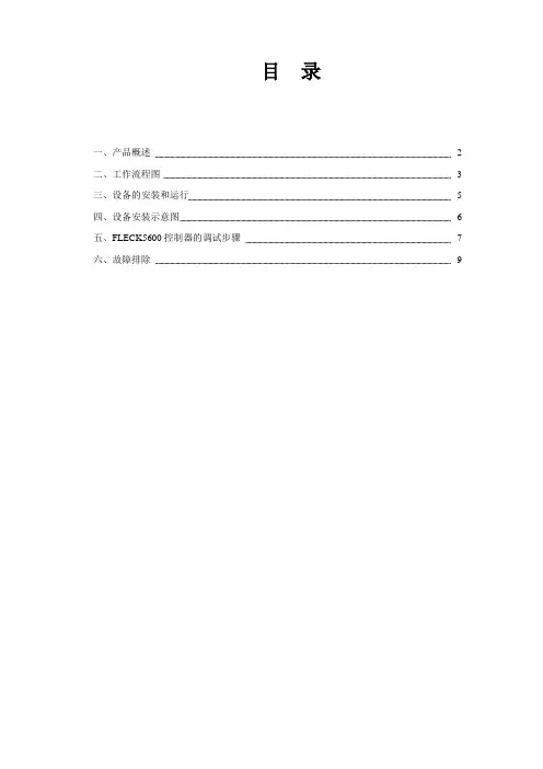
目录一、产品概述 2二、工作流程图 3三、设备的安装和运行 5四、设备安装示意图 6五、FLECK5600控制器的调试步骤7六、故障排除9产品概述首先感谢您使用本公司的全自动软化水设备!为着方便您的使用,我们编写了该产品的客户手册,您的认真阅读和理解一定能为产品的良好使用打下基础。
5600系列自动软水器分为时间周期型和流量周期型两种控制方式,用户可以根据当地水质及用户对于水质的要求来进行选择。
本产品广泛应用于蒸汽和热水锅炉、热交换设备、食品加工、造纸印刷、洗衣印染、家庭、宾馆饭店、医疗制药、纯水制备预处理等行业。
我公司将给用户提供完善的技术及售后服务。
自动软水器技术参数:入口水压:0.2Mpa-0.6Mpa工作温度:2-50℃电源型式:220V/50Hz AC电源功率:3W出口硬度:≤0.03mmol/L再生方式:动态顺流再生或逆流再生树脂型号:001×7强酸性阳离子交换树脂盐耗:<160-240g/mol(根据水质情况)FLECK5600控制器工作流程图说明:FLECK5600和56SE控制器的水流过程略为不同,但原理一致。
1、工作状态2、预清洗(5min)3、反洗(10min)4、吸盐(50min)硬水经控制器进水口向下流过中心管、下布水器,向上流经树脂层,流出排水口,进行反洗。
硬水经控制器进水口流过树脂层,软化后经下布水器、中心管向上流出出水口,此时设备处于工作状态。
硬水经控制器进水口流过树脂层,软化后经下布水器、中心管向上流出排水口,进行预清洗。
硬水经控制器进水口,通过射流器,吸入盐液再生剂,向下流过树脂层进行再生还原,最后通过下布水器、中心管和排水口流出。
5、慢洗6、快洗7、稳层清洗 8、盐箱充水吸盐完成后,空气止回阀会将吸盐口封住,防止空气的进入,硬水继续经控制器进水口,通过射流器,向下流过树脂层,最后通过下布水器、中心管和排水口流出。
硬水经控制器进水口,向下通过中心管、下布水器,然后向上流过树脂层,最后通过排水口流出。


5600 5600SE全自动软化水设备安装、运行及维护手册目录一、产品概述二、工作流程图三、设备的安装和运行四、设备安装示意图五、FLECK5600控制器的调试步骤六、FLECK56SE控制器的调试步骤七、FLECK56SE控制器全面编程及相关代号的意义列表八、故障排除产品概述首先感谢您使用本公司的全自动软化水设备!为着方便您的使用,我们编写了该产品的客户手册,您的认真阅读和理解一定能为产品的良好使用打下基础。
5600系列自动软水器分为时间周期型和流量周期型两种控制方式,用户可以根据当地水质及用户对于水质的要求来进行选择。
本产品广泛应用于蒸汽和热水锅炉、热交换设备、食品加工、造纸印刷、洗衣印染、家庭、宾馆饭店、医疗制药、纯水制备预处理等行业。
我公司将给用户提供完善的技术及售后服务。
自动软水器技术参数:入口水压:0.2Mpa-0.6Mpa 工作温度:2-50℃ 电源型式:220V/50Hz AC 电源功率:3W出口硬度:≤0.03mmol/L再生方式:动态顺流再生或逆流再生 树脂型号:001×7强酸性阳离子交换树脂 盐 耗:<160-240g/mol (根据水质情况)FLECK5600/56SE 控制器工作流程图说明:FLECK5600和56SE 控制器的水流过程略为不同,但原理一致。
1、 工作状态2、预清洗(5min )硬水经控制器进水口流过树脂层,软化后经下布水器、中心管向上流出出水口,此时设备处于工作状态。
硬水经控制器进水口流过树脂层,软化后经下布水器、中心管向上流出排水口,进行预清洗。
3、反洗(10min)4、吸盐(50min)5、慢洗6、快洗硬水经控制器进水口向下流过中心管、下布水器,向上流经树脂层,流出排水口,进行反洗。
硬水经控制器进水口,通过射流器,吸入盐液再生剂,向下流过树脂层进行再生还原,最后通过下布水器、中心管和排水口流出。
吸盐完成后,空气止回阀会将吸盐口封住,防止空气的进入,硬水继续经控制器进水口,通过射流器,向下流过树脂层,最后通过下布水器、中心管和排水口流出。
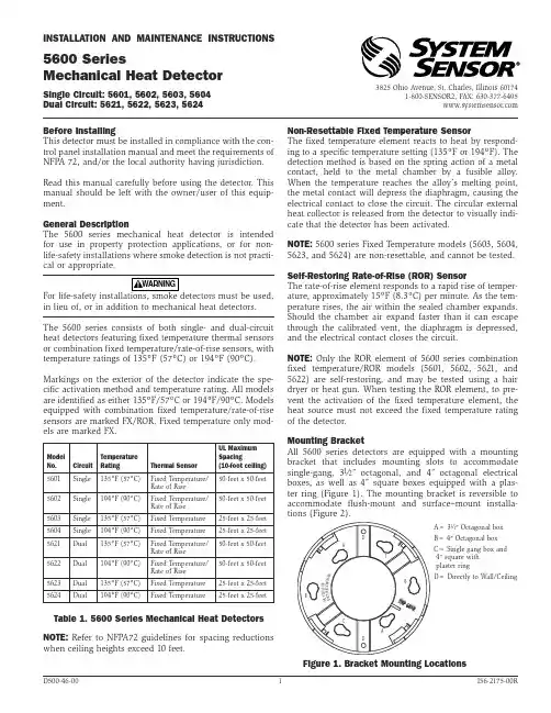
Before InstallingThis detector must be installed in compliance with the con-trol panel installation manual and meet the requirements of NFPA 72, and/or the local authority having jurisdiction. Read this manual carefully before using the detector. This manual should be left with the owner/user of this equip-ment.General DescriptionThe 5600 series mechanical heat detector is intended for use in property protection applications, or for non-life-safety installations where smoke detection is not practi-cal or appropriate.in lieu of, or in addition to mechanical heat detectors. The 5600 series consists of both single- and dual-circuit heat detectors featuring fixed temperature thermal sensors or combination fixed temperature/rate-of-rise sensors, with temperature ratings of 135ºF (57ºC) or 194ºF (90ºC).Markings on the exterior of the detector indicate the spe-cific activation method and temperature rating. All models are identified as either 135ºF/57ºC or 194ºF/90ºC. Models equipped with combination fixed temperature/rate-of-rise sensors are marked FX/ROR. Fixed temperature only mod-els are marked FX.NOTE: Refer to NFPA72 guidelines for spacing reductions when ceiling heights exceed 10 feet.Non-Resettable Fixed Temperature SensorThe fixed temperature element reacts to heat by respond-ing to a specific temperature setting (135ºF or 194ºF). The detection method is based on the spring action of a metal contact, held to the metal chamber by a fusible alloy. When the temperature reaches the alloy’s melting point, the metal contact will depress the diaphragm, causing the electrical contact to close the circuit. The circular external heat collector is released from the detector to visually indi-cate that the detector has been activated.NOTE: 5600 series Fixed T emperature models (5603, 5604, 5623, and 5624) are non-resettable, and cannot be tested.Self-Restoring Rate-of-Rise (ROR) SensorThe rate-of-rise element responds to a rapid rise of temper-ature, approximately 15ºF (8.3ºC) per minute. As the tem-perature rises, the air within the sealed chamber expands. Should the chamber air expand faster than it can escape through the calibrated vent, the diaphragm is depressed, and the electrical contact closes the circuit.NOTE: Only the ROR element of 5600 series combination fixed temperature/ROR models (5601, 5602, 5621, and 5622) are self-restoring, and may be tested using a hair dryer or heat gun. When testing the ROR element, to pre-vent the activation of the fixed temperature element, the heat source must not exceed the fixed temperature rating of the detector.Mounting BracketAll 5600 series detectors are equipped with a mounting bracket that includes mounting slots to accommodate single-gang, 31⁄2″ octagonal, and 4″ octagonal electrical boxes, as well as 4″ square boxes equipped with a plas-ter ring (Figure 1). The mounting bracket is reversible to accommodate flush-mount and surface–mount installa-tions (Figure 2).INSTALLATION AND MAINTENANCE INSTRUCTIONS3825 Ohio Avenue, St. Charles, Illinois 601741-800-SENSOR2, FAX: 630-377-64955600 SeriesMechanical Heat DetectorSingle Circuit: 5601, 5602, 5603, 5604Dual Circuit: 5621, 5622, 5623, 5624Table 1. 5600 Series Mechanical Heat Detectors Figure 1. Bracket Mounting LocationsA= 31⁄2″ Octagonal boxB= 4″ Octagonal box C= Single gang box and 4″ square with plaster ringD= Directly to Wall/CeilingS T R IP G A U G EBCDDAABCModel No.CircuitTemperatureRatingThermal SensorUL Maximum Spacing(10-foot ceiling)5601Single 135ºF (57ºC)Fixed T emperature/Rate of Rise 50-feet x 50-feet 5602Single 194ºF (90ºC)Fixed T emperature/Rate of Rise 50-feet x 50-feet 5603Single 135ºF (57ºC)Fixed T emperature 25-feet x 25-feet 5604Single 194ºF (90ºC)Fixed T emperature 25-feet x 25-feet 5621Dual 135ºF (57ºC)Fixed T emperature/Rate of Rise 50-feet x 50-feet 5622Dual 194ºF (90ºC)Fixed T emperature/Rate of Rise 50-feet x 50-feet5623Dual 135ºF (57ºC)Fixed T emperature 25-feet x 25-feet 5624Dual194ºF (90ºC)Fixed T emperature25-feet x 25-feetWiring Installation GuidelinesAll wiring must be installed in compliance with the National Electrical Code, applicable state and local codes, and any special requirements of the local Authority Having Jurisdiction. Proper wire gauges should be used. The conductors used to connect heat detectors to the alarm control panel and accessory devices should be color-coded to reduce the likelihood of wiring errors. Improper connec-tions can prevent a system from responding properly in the event of a fire.The non-polarized screw terminals on the back of the detector will accept 14–22 A WG wire. For best system performance, all wiring should be installed in separate grounded conduit; do not mix fire alarm system wiring in the same conduit as any other electrical wiring. T wisted pair may be used to provide additional protection against extraneous electrical interference.Wire connections are made by stripping approximately 1⁄4″ of the insulation from the end of the feed wire, inserting it into the proper base terminal, and tightening the screw to secure the wire in place.InstallationRemove power from the alarm control unit or initiating device circuits before installing detectors.1. Detach the detector from the mounting bracket byrotating the detector 1⁄4 turn counter-clockwise.2. Orient the mounting bracket properly for either aflush- or surface-mount installation (Figure 2).3. Select the pair of mounting holes suitable for the junc- tion box, (figure 1) and secure the bracket to the box.4. Connect the wires to the detector per Figure 3 orFigure 4, as applicable.5. Place the detector onto the mounting bracket by rotat- ing clockwise. The detector will lock into place with a “click”.6. After all detectors have been installed, apply power to the alarm control unit.7. T est each detector as described in Testing.8. Reset all the detectors at the alarm control unit.9. Notify the proper authorities that the system is in oper- ation.Figure 3. Wiring Diagram – Single Circuit ModelsFigure 4. Wiring Diagram – Dual Circuit Models Testing/MaintenanceThe rate-of-rise mechanism may be subject to reduced sen-sitivity over time. Annual testing of the rate-of-rise opera-tion is therefore recommened.Before testing, notify the proper authorities that mainte-nance is being performed and the system will be temporar-ily out of service. Disable the zone or system undergoing maintenance to prevent any unwanted alarms.Only the ROR element of 5600 series combination fixed temperature/ROR models (5601, 5602, 5621, and 5622) are self-restoring, and may be tested using a hair dryer or heat gun.Figure 2. Reversible Mounting BracketEOLControlSurface–mountFlush–mountControlEOLWhen testing the ROR element, to prevent the activation of the fixed temperature element, the heat source must not exceed the fixed temperature rating of the detector.5600 series fixed(5603, 5604, 5623, and 5624) are non-resettable, and cannot be tested.Specifications:Operating Voltage /Contact Ratings 6 – 125 V AC / 3A (Resistive) 6 – 28 VDC / 1A 125 VDC / 0.3A 250 VDC / 0.1A Maximum InstallationT emperature Models 5601, 5603, 5621, and 5623: 100°F (38°C) Models 5602, 5604, 5622, and 5624:150°F (65.6°C)Alarm T emperature Models 5601, 5603, 5621, and 5623: 135°F (57°C) Models 5602, 5604, 5622, and 5624: 194°F (90°C)Rate-of-Rise Threshold 15°F (8.3°C) per minute(models 5601, 5602, 5621, and 5622 only) Operating HumidityRange 5 to 95% RH non-condensing Input T erminals 14 - 22 A WG Back Box Mounting 31⁄2″ octagonal 4″ octagonal Single gang4″ square with a square to round plaster ring Dimensions withmounting bracket Diameter: 4.57 inches (11.6cm) Height: 1.69 inches (4.3cm)Weight 6 oz. (170 grams)Please refer to insert for the Limitations of Fire Alarm SystemsSystem Sensor warrants its enclosed module to be free from defects in materials and workmanship under normal use and service for a period of three years from date of manufacture. System Sensor makes no other express warranty for this module. No agent, representative, dealer, or employee of the Company has the authority to increase or alter the obligations or limitations of this Warranty. The Company’s obli-gation of this Warranty shall be limited to the replacement of any part of the module which is found to be defective in materials or workmanship under normal use and service during the three year period commencing with the date of manufacture. After phoning System Sensor’s toll free number 800-SENSOR2 (736-7672) for a Return Authorization number, send defective units postage prepaid to: System Sensor, Repair Department, RA #__________, 3825 Ohio Avenue, St. Charles, IL 60174.FCC StatementThis device complies with part 15 of the FCC Rules. Operation is subject to the following two conditions: (1) This device may not cause harmful interference, and (2) this device must accept any interference received, including interference that may cause undesired operation.Note: This equipment has been tested and found to comply with the limits for a Class B digital device, pursuant to Part 15 of the FCC Rules. These limits are designed toprovide reasonable protection against harmful interference in a residential installation. This equipment generates, uses and can radiate radio frequency energy and, if not installed and used in accordance with the instructions, may cause harmful interference to radio communications. However, there is no guarantee that interference will not occur in a particular installation. If this equipment does cause harmful interference to radio or television reception, which can be determined by turning the equipment off and on, the user is encouraged to try to correct the interference by one or more of the following measures:– Reorient or relocate the receiving antenna. – Increase the separation between the equipment and receiver. – Connect the equipment into an outlet on a circuit different from that to which the receiver is connected. – Consult the dealer or an experienced radio/TV technician for help.Please include a note describing the malfunction and suspected cause of failure. The Company shall not be obligated to replace units which are found to be defective because of damage, unreasonable use, modifications, or alterations occurring after the date of manufacture. In no case shall the Company be liable for any consequen-tial or incidental damages for breach of this or any other Warranty, expressed or implied whatsoever, even if the loss or damage is caused by the Company’s negli-gence or fault. Some states do not allow the exclusion or limitation of incidental or consequential damages, so the above limitation or exclusion may not apply to you. This Warranty gives you specific legal rights, and you may also have other rights which vary from state to state.Three-Year Limited Warranty。

FLECK5600SE控制器全自动软化水设备操作使用手册北京普瑞特水处理技术开发有限公司FLECK56SE控制器调试步骤一:准备工作和注意事项a、软水设备在调试及运行前应按厂家要求安装完毕进、出水、排污管道和阀门;b、自来水、电源及排水沟准备就绪;c、打开旁通阀,让自来水冲洗管道至出水变清,然后关闭阀门;d、控制器再生程序分别为:1、反洗(Backwash)2、吸盐与慢洗(Brine/Rinse)3、快洗(Rinse)4、盐箱注水(Brine Refill)。
工作指示工作状态—灯亮当天再生—灯闪—灯闪编程模式指示灯正向Up再生反向Down二:调试工作1. 整控制器到工作位置,让水流进树脂罐,当水流停止时,打开阀门以放尽罐中空气,然后关闭阀门;2.插上电源,观察是否工作;3.控制器时间设定,按动Up或Down键可调整时间,连续按住可连续调整;4.控制器简单编程(控制器时间非12:01PM)a.同时按住Up或Down键,5秒后控制器进入编程模式,此时编程指示灯亮,每按一次Extra Cycle键,控制器程序进入下一步程序;b.产水量设定按动Up或Down键可以设定软水器再生前的产水量;c.A Off:流量型专用参数,不得更改。
d.退出编程按动Extra Cycle键,控制器退出编程模式。
5.控制器全面编程按动Up或Down键,将时间设定为12:01PM(必须设定为该时间,才可以进行全部程序内容的调试);然后通过按动Up、Down、Extra Cycle键即可进行对控制器全部程序内容的编程,程序内容及步骤见附表《控制器全面编程及相关代号的意义列表。
》6、软水器即时再生方式按动Extra Cycle键,开始再生程序- - -a、对于即时再生控制器,按动Extra Cycle键后,即开始再生程序;b、对于延时再生控制器,按动Extra Cycl键后,工作状态指示灯开始闪动,控制器将在当日的预先设定时间开始再生程序;c、按住Extra Cycle键5秒钟后,延时再生类型控制器即被强制进入再生程序;7、再生步骤按动Extra Cycle键,控制器进入再生程序(此前,盐箱加满大盐粒,禁用细盐、碘盐、将水加至空气止回阀顶部)a、控制器进入步骤1(RINSE),快洗3-8分钟,按动Extra Cycle键;b、控制器进入步骤2(BACK WASH),反洗1-8分钟,按Extra Cycle健;c、控制器进入步骤3(BRINE/RINSE),吸盐/慢洗2-58分钟,按动Extra Cycle健;d、控制器进入步骤4(REPID RINSE),注水2-11分钟;e、按动Extra Cycle健,控制器返回工作状态。

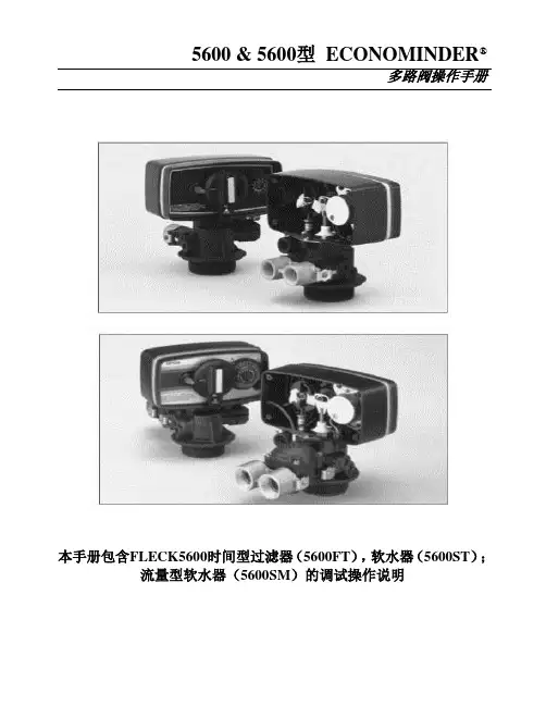
5600 & 5600型ECONOMINDER®多路阀操作手册本手册包含FLECK5600时间型过滤器(5600FT),软水器(5600ST);流量型软水器(5600SM)的调试操作说明5600产品概述FLECK全自动控制器以闻名于世的FLECK公司软化水技术为基础,它是将软水器的运行及再生的每一个步骤实现全自动控制,并采用时间、流量或感应器等方式来启动再生。
由于FLECK系列全自动软水设备控制系统技术成熟、操作简便、富来控制器采用的工程塑料和无铅黄铜阀体完全符合食品卫生要求,配以聚四氟乙烯(Teflon)涂层,活塞减小了阻力,延长了使用寿命,运行可靠。
FLECK系列全自动软水器可用于家用、工业锅炉、热交换器、宾馆饭店、食品工业、洗衣印染、医疗卫生等行业,该产品具有自动化程度高、交换容量大、结构紧凑、能耗低、省人工、无需日常保养等特点。
系统技术参数进口压力:0.2 Mpa-0.6 Mpa工作温度:2 ℃—50℃进水硬度:符合国家标准出水硬度:≤0.03mmol/L使用电源:220v/50Hz AC布置形式:单罐或双罐串联(二级软化时采用)再生方式:顺流再生操作程序:自动程序控制使用树脂:001×7强酸性阳离子交换树脂我公司将为用户提供完善的技术服务及售后服务。
第1页5600ST安装和启动程序软水器的安装,应根据制造商建议的入水口、出水口和排污口接管,且应符合相关管路规范。
在软水装置接通电源前1.将软水器控制阀手动转至工作位置,打开进出水口,使水流入树脂罐。
直到管路内空气排尽,当水流流出出水口时,关闭进出水口。
注:可手动旋转控制阀前部的旋钮将其拨至不同的再生位置,直到显示软水器处于所需位置。
2.将控制阀手动转至反洗位置,使水经排水口流出3或4分钟。
3.取下控制阀后盖板。
4.确保盐的用量按制造商的建议设置。
如有必要,按设置说明书设置盐的用量。
将控制阀手动转至盐水重注位置,使水填充至空气止回阀顶。
目录一、产品概述2二、工作流程图3三、设备的安装和运行5四、设备安装示意图6五、FLECK5600控制器的调试步骤7六、故障排除9产品概述首先感谢您使用本公司的全自动软化水设备!为着方便您的使用,我们编写了该产品的客户手册,您的认真阅读和理解一定能为产品的良好使用打下基础。
5600系列自动软水器分为时间周期型和流量周期型两种控制方式,用户可以根据当地水质及用户对于水质的要求来进行选择。
本产品广泛应用于蒸汽和热水锅炉、热交换设备、食品加工、造纸印刷、洗衣印染、家庭、宾馆饭店、医疗制药、纯水制备预处理等行业。
我公司将给用户提供完善的技术及售后服务。
自动软水器技术参数:入口水压:0.2Mpa-0.6Mpa工作温度:2-50℃电源型式:220V/50Hz AC电源功率:3W出口硬度:≤0.03mmol/L再生方式:动态顺流再生或逆流再生树脂型号:001×7强酸性阳离子交换树脂盐耗:<160-240g/mol(根据水质情况)FLECK5600控制器工作流程图说明:FLECK5600和56SE控制器的水流过程略为不同,但原理一致。
1、工作状态2、预清洗(5min)3、反洗(10min)4、吸盐(50min)5、慢洗6、快洗7、稳层清洗 8、盐箱充水设备的安装和运行一、一般要求a、软水器应安装在牢固的水泥平台上,附近应设有排水沟;b、盐罐的安放应靠近树脂罐,并尽量缩短吸盐管的长度;c、环境温度不能低于2℃或高于50℃;d、软水器与加热设备直接相连时,应保持3米以上的管段并安装单向阀;e、要便于再生剂的补充;f、设备附近应当留有操作及维修空间。
二、控制器安装与树脂装填a、装填前应将升降管(带下布水器)放入树脂罐中央低于罐口0.5mm处截断并导角此后应用胶带封住升降管口,(为防止石英砂和树脂进入升降管);b、将石英砂沿升降管周围空隙投入树脂罐,并使之在罐底铺平;c、将处理好的树脂按照规定的装填量沿升降管周围投入树脂罐。
润新软水机说明书-CAL-FENGHAI.-(YICAI)-Company One1目录一、产品概述2二、工作流程图3三、设备的安装和运行5四、设备安装示意图6五、FLECK5600控制器的调试步骤7六、故障排除9产品概述首先感谢您使用本公司的全自动软化水设备!为着方便您的使用,我们编写了该产品的客户手册,您的认真阅读和理解一定能为产品的良好使用打下基础。
5600系列自动软水器分为时间周期型和流量周期型两种控制方式,用户可以根据当地水质及用户对于水质的要求来进行选择。
本产品广泛应用于蒸汽和热水锅炉、热交换设备、食品加工、造纸印刷、洗衣印染、家庭、宾馆饭店、医疗制药、纯水制备预处理等行业。
我公司将给用户提供完善的技术及售后服务。
自动软水器技术参数:入口水压:工作温度:2-50℃电源型式:220V/50Hz AC电源功率:3W出口硬度:≤L再生方式:动态顺流再生或逆流再生树脂型号:001×7强酸性阳离子交换树脂盐耗:<160-240g/mol(根据水质情况)FLECK5600控制器工作流程图说明:FLECK5600和56SE 控制器的水流过程略为不同,但原理一致。
1、工作状态2、预清洗(5min )3、反洗(10min)4、吸盐(50min )硬水经控制器进水口流过树脂层,软化后经下布水器、中心管向上流出出水口,此时设备处于工作状态。
硬水经控制器进水口流过树脂层,软化后经下布水器、中心管向上流出排水口,进行预清洗。
5、慢洗6、快洗7、稳层清洗 8、盐箱充水硬水经控制器进水口向下流过中心管、下布水器,向上流经树脂层,流出排水口,进行反洗。
硬水经控制器进水口,通过射流器,吸入盐液再生剂,向下流过树脂层进行再生还原,最后通过下布水器、中心管和排水口流出。
吸盐完成后,空气止回阀会将吸盐口封住,防止空气的进入,硬水继续经控制器进水口,通过射流器,向下流过树脂层,最后通过下布水器、中心管和排水口流出。
Master Programming Mode Flow Chart for Single Backwash ValvesWith Time of Day display set to 12:01 P.M., push and hold both the Set Up and Set Down buttons for 5 /Metric Display FormatExample: US display Format [U--1]Regeneration TypeExample: Meter Delayed Regeneration [7--3]Treated Water CapacityExample: 1,000 gallons/liters/cubic meters [1000]Regeneration TimeExample: Regenerate as needed at 2:00 A.M. [2:00]Regeneration Day OverrideExample: Regenerate at a minimum frequency of 3 days [A--3]Regeneration Cycle Step #1Example: 10 minute step time [1-10]Regeneration Cycle Step #2Example: 60 minute step time [2-60]Regeneration Cycle Step #3Example: 10 minute step time [3-10]Regeneration Cycle Step #4Example: 12 minute step time [4-12]Regeneration Cycle Step #5Example: Step 5 Cancelled [5OFF]Flow Meter SizeExample: 5600SE 3/4" Turbine Flow Meter [F133]Valve TypeExample: 5600SE Valve [o--1]Line FrequencyExample: 60 Hz Line Frequency [LF60]Master Programming Mode is exited,Normal Operation is resumedNOTE:1.Set Time of Day display to 12:01 P.M.2.Push and hold both the Set Up and Set Down buttons for 5 seconds.3.Push Extra Cycle button once per display until all displays are viewed and Normal Operation is resumed.4.Option setting displays may be changed as required by pushing either the Set Up or Set Down button.5.Depending on current valve programming certain displays will not be able to be viewed or set.6.Reference programming instructions for complete list of available settings.Page 1Master Programming Mode Flow Chart for Double Backwash ValvesWith Time of Day display set to 12:01 P.M., push and hold both the Set Up and Set Down buttons for 5 /Metric Display FormatExample: US display Format [U--1]Regeneration TypeExample: Meter Delayed Regeneration [7--3]Treated Water CapacityExample: 1,000 gallons/liters/cubic meters [1000]Regeneration TimeExample: Regenerate as needed at 2:00 A.M. [2:00]Regeneration Day OverrideExample: Regenerate at a minimum frequency of 3 days [A--3]Regeneration Cycle Step #1Example: 10 minute step time [1-10]Regeneration Cycle Step #2Example: 60 minute step time [2-60]Regeneration Cycle Step #3Example: 10 minute step time [3-10]Regeneration Cycle Step #4Example: 10 minute step time [4-10]Regeneration Cycle Step #5Example: 12 minute step time [5-12]Regeneration Cycle Step #6Example: Step 6 Cancelled [6OFF]Flow Meter SizeExample: 5600SE 3/4" Turbine Flow Meter [F133]Valve TypeExample: 5600SE Valve [o--1]Line FrequencyExample: 60 Hz Line Frequency [LF60]Master Programming Mode is exited,Normal Operation is resumedNOTE:1.Set Time of Day display to 12:01 P.M.2.Push and hold both the Set Up and Set Down buttons for 5 seconds.3.Push Extra Cycle button once per display until all displays are viewed and Normal Operation is resumed.4.Option setting displays may be changed as required by pushing either the Set Up or Set Down button.5.Depending on current valve programming certain displays will not be able to be viewed or set.6.Reference programming instructions for complete list of available settings.Page 2Master Programming ModeSet Up buttonExtra Cycle button Set Down buttonWhen the Master Programming Mode is entered, all available option setting displays may be viewed and set as needed. Depending on current option settings, some displays cannot be viewed or set.Entering Master Programming ModeSet the Time Of Day display to 12:01 P.M. Push and hold the Set Up and Set Down buttons together until the Program Dot turns on (about 5 seconds). Depending on current option settings, some displays cannot be viewed or set.Exiting Master Programming ModePush the Extra Cycle button once per display until all are viewed. The Program Mode is exited and normal operation resumes. Resetting Permanent Programming MemoryPush and hold the Set Up and Set Down buttons for 25 seconds or until the Time Of Day display resets to 12:00 P.M. All option settings reset to default values. Control programming must be reset as necessary./Metric Display Format (U)Push the Extra Cycle button. This display is used to set the desired display format. This option setting is identified by the "U"in the first digit. The possible settings are:US Format uses gallons for volume with a 12-hour timekeeping format. Regeneration timing in minutes.Example:[U - - I]Metric Format uses liters for volume and a 24-hour timekeeping format. Regeneration timing in tenths of minutes. Use the Set Up and Set Down buttons to adjust this value.Example:[U - - 2]Cubic Meter Format uses cubic meters for volume and a 24-hour timekeeping format. Regeneration timing in tenths of minutes. Use the Set Up and Set Down buttons to adjust this value.Example:[U - - 4]Page 3Master Programming Mode (Cont’d.)2.Regeneration Type (7)Push the Extra Cycle button. Use this display to set the Regeneration Type. This option setting is identified by the number "7"in the first digit. There are three possible settings:Timeclock DelayedThe control determines the day that a regeneration is required by the Regeneration Day Override setting (A). Once this day is reached, a regeneration cycle starts at the set Regeneration Time.Example:[7 - - I]Meter ImmediateThe control determines that regeneration is required when the available volume of treated water drops to zero. Regeneration begins immediately.Example:[7 - - 2] (This setting is typically used by the 9000SE)Meter DelayedThe control determines that a regeneration is required when the available volume of treated water drops to zero. Regeneration begins immediately at the set Regeneration Time. Use the Set Up and Set Down buttons to adjust this value.Example:[7 - - 3]3.Treated Water Capacity (No Display Code)Push the Extra Cycle button. Use this display to set the amount of water (gallons/liters/cubic meters) that can be treated by the unit before a regeneration cycle is required. With Meter Delayed Regeneration Type set, it is necessary for the programmer to determine a reserve capacity and subtract that value from the calculated full capacity of the unit. This display cannot be viewed with Timeclock Regeneration Type set. Use the Set Up and Set Down buttons to adjust this value.Example:Regenerate every 700 gallons/liters/cubic meters —[7 0 0]4.Regeneration Time (Clock Display Without a Flashing Colon)Push the Extra Cycle button. The next display that appears is the option setting for Regeneration Time. It is identified by a clock display without a flashing colon. Set the desired time of day that a regeneration may occur. This display cannot be viewed with Meter Immediate Regeneration Type set. Use the Set Up and Set Down buttons to adjust this value.Example: 2 o'clock A.M. Regeneration Time —[2: 0 0] (A.M. Indicator Dot On)5.Regeneration Day Override (A)Push the Extra Cycle button. Use this display to set the maximum amount of time (in days) the unit can be in service withouta regeneration. This option setting is identified by the letter "A" in the first digit.–With Timeclock or Meter Delayed Regeneration Types selected, regeneration begins at the set Regeneration Time.–With Meter Immediate Regeneration Type selected, regeneration begins at the same time of day that the last regeneration cycle was initiated. An OFF setting cancels this feature with all regeneration types except Timeclock Regeneration were it must be used. Use the Set Up and Set Down buttons to adjust this value.Example:Override every 7 days — [A - - 7]Cancel setting — [A O F F] (Meter Immediate or Delayed Regeneration Types Only)Page 4Master Programming Mode (Cont’d.)6.Regeneration Cycle Step Programming (1) (2) (3) (4) (5) (6)Push the Extra Cycle button. The next 2–6 displays that appear are part of a series of option settings used to program the Regeneration Cycle. Each display is used to set in minutes (or tenths of minutes - Metric). A step # turns on for theregeneration cycle step being programmed.–Skip regeneration steps by setting the display to 0–End a regeneration cycle by setting the step # after the last active step to OFF, as shown below:Example:Regeneration Cycle Step #1, 8 minutes —[I - - 8](US Format)Regeneration Cycle Step #3, skipped — [3 - - 0] (US Format)Regeneration Cycle Step #4, 8.5 minutes —[4 - 8.5] (Both Metric Formats)Regeneration Cycle Step #4, cancelled —[4 O F F] (All Formats)Push the Extra Cycle button once per display to advance through Regeneration Cycle Step Programming.Proper softener operation requires the calculation of a brine tank refill time:(Pounds of Salt Used per Regeneration Cycle ÷ 3) ÷ BLFC Size = Refill Time in MinutesExample:(10 lbs salt ÷ 3) ÷ 0.25 gpm = 13.3 minute refill(Consult valve service manual for actual step location)Use the Set Up and Set Down buttons to adjust this value.7.Flow Meter Size (F)Push the Extra Cycle button. The the next display sets the flowmeter size. Use this display to set the proper amount of pulses generated by the flow meter for each gallon or liter of water flow. This setting cannot be viewed with Timeclock Regeneration Type selected.Example:[F I 2 6] 3/4” Turbine Flow Meter used with the 2510SE (US Format)Example:[F 3 3.2] 3/4” Turbine Flow Meter used with the 2510SE (Metric Format)Example:[F 1 3 2]3/4” Turbine Flow Meter used with the TwinFlo100E (US Format)Example:[F 3 4.9] 3/4” Turbine Flow Meter used with the TwinFlo100E (Metric Format)Example:[F 1 3 3]3/4” Turbine Flow Meter used with the 5600SE or 9000SE (US Format)Example:[F 3 5.1] 3/4” Turbine Flow Meter used with the 5600SE or 9000SE (Metric Format)Example:[F - 2 0] 3/4” Paddle Wheel Flow Meter (US Format)Example:[F - 5.3] 3/4” Paddle Wheel Flow Meter (Metric Format)Example:[F - - 8] 1.0” Paddle Wheel Flow Meter (US Format)Example:[F - 2.1] 1.0” Paddle Wheel Flow Meter (Metric Format)Use the Set Up and Set Down buttons to adjust this value.8.Valve Type (o)Push the Extra Cycle button. Use this display to set the type of valve used with the control. This option setting is identified by the letter "o" in the first digit. When #2 is selected, the current Tank # in Service must be entered in the next display.Example:[o - - I] 2510SE, 2750SE or 5600SE Valve Operation.Example:[o - - 2]9000SE or TwinFlo100E Valve Operation.Example:[o - U I] Unit #1 Tank in Service. (Viewed with #2 set only)Use the Set Up and Set Down buttons to adjust this value.Page 5Master Programming Mode (Cont’d.)9.Line Frequency (LF)Push the Extra Cycle button. Use this display to set the frequency of the power applied to the control. When properly set, all timekeeping functions remain accurate. This option setting is identified by the letters "LF" in the first two digits. There are two possible selections.Example:[L F 5 0] 50 Hz Line Frequency Operation.Example:[L F 6 0] 60 Hz Line Frequency Operation.Use the Set Up and Set Down buttons to adjust this value.Push the Extra Cycle button once more to exit this programming mode.Page 6P/N 41674 Rev. A。