KlippelQCsystem操作说明书
- 格式:pdf
- 大小:4.24 MB
- 文档页数:25

操作手册根据程序软件2.07版本200/008-545,B-10/2004Quick GuideAppendix to Quick GuideAnnexes (8)DiaSorin S.p.A.Strada per Crescentino - 13040 Saluggia (Vercelli) - ItalyTel. 39.0161.487.093 - Fax 39.0161.487.628内容1.仪器简介 (4)2.仪器每日使用程序 (6)3.术语及解释 (7)4.测试准备 (8)4.1 打开系统 (8)4.2 关闭系统 (9)4.3 补充系统消耗品 (11)4.4 试剂盒准备 (13)4.5 装载试剂盒 (14)4.6 样本准备 (15)4.7 装载样本 (16)4.8 数据保存 (20)4.9 电子版说明书 (21)4.10 移液针头定位 (22)5.检查仪器状态 (24)5.1 消耗品 (24)5.1.1 清洗液/系统液,启动试剂和反应舱 (24)5.1.2 温度和电压 (25)5.1.3 废液罐—废品袋 (25)6.系统测试 (27)6.1 装载样本架 (27)6.2 选择测试 (27)6.3 结果评估 (28)7 试剂盒的使用和定标 (29)7.1 试剂盒装载 (29)7.2 检查试剂盒定标状态 (29)7.3 定标 (30)7.4 试剂盒使用完毕 (30)8.样本测试 (31)9.结果管理 (33)9.1 结果显示 (33)9.2 结果确认 (34)9.3 “Daily Lab-Journal”和“Valid menu” (34)10.日常维护 (36)10.1 每日维护 (36)10.2 每周维护 (36)10.3 每月维护 (37)第一章仪器简介说明:1.机械臂(左臂和右臂)[Pipettors (left & right)]2.反应舱装载带(Cuvette loader)3.反应杯贮存器(Stacker)4.样本区(Sample Area)5.试剂区(Reagent Area)6.孵育器装载器(Incubator loader)7.清洗装载器(Washer loader)8.孵育器(Incubator)9.清洗传送器(Washer transport)10.清洗头(Washer lift)11.清洗器[Diluters (left & right)]12.回传传送器(Back-transport)13.推动器(Pusher)14.检测室(Measure chamber)15.条形码阅读器(Barcode reader)移液针头定位器(Teacher)16.废品袋(Waste bag)17.启动试剂区(Starter Area)说明(包括消耗品的产品号码)1.光检测试剂(319101)2.启动试剂(319102)3.清洗液/系统液(319100)4.试剂盒5.反应舱(319130)6.清洗液/系统液罐7.废液罐8.“A” 型样本架*9.“L” 型样本架*10.“P” 型样本架*11.废品袋(450003)*注意:有的样本架只有10个位子。

安捷伦高效液相色谱仪操作说明一、校枪及样品处理1. 校枪仪器:两个小烧杯、分析天平、移液枪1000μL、100μL步骤:打开分析天平预热,一只烧杯放到称量盘上调零,一只装入纯水。
将移液枪1000μL、100μL调至950μL、50μL,分别吸取纯水称质量,如偏大或偏小,调节移液枪直至准确到0.001g。
(如枪使用过久或气密性不好,可以准备一个小烧杯装入纯水,每次先轻轻沾湿枪口,甩掉水或在用卫生纸吸取口上的水,再插上枪头使用。
)注意慢吸慢放,不要挂珠。
2. 样品处理:用1.5mL离心管取0.5mL发酵液,取出样品后,首现在离心机上离心(13000rap/min 3min)。
然后将样品稀释20倍,取950μL纯水、50μL发酵液于离心管中。
混匀后在离心机上离心(13000rap/min 3min)。
准备自动进样瓶(瓶中放上内衬管),取200μL待测液盖紧盖子。
按顺序放到自动进样盘中。
二、开机1、仪器各组件将在线脱气器、泵:四元、进样器:自动进样器(六通阀)、柱温箱、检测器:示差折光检测器开关打开。
打开计算机,进入Windows XP 画面,并运行CAC Server程序,打开色谱仪各组件电源,待显示已联上各组件的信息及各模块自检完成后,双击Instrument 1 Online ,图标打开工作站。
化学工作站自动与1200LC通讯。
流动相:将流动相(一般不主张使用偏酸、偏碱的流动相)放入溶剂瓶中,打开冲洗阀,设流速为2ml/min,单击确定,再依次单击泵→控制,选中启动,单击确定,则系统开始冲洗,至管路无气泡为止,切换管路反复操作至所需管路均无气泡。
在“控制”选项中选“关闭”,关闭泵,关闭冲洗阀。
单击泵下面瓶图标,输入溶剂的实际体积和瓶体积。
每次四元泵开始前,要打开冲洗阀阀门以5ml/min的流速冲洗10分钟,使脱气机与泵之间的流动相从冲洗阀流出,以免隔夜的流动相损伤色谱柱。
每次进样检测前,要用流动相冲洗色谱柱30分钟,达到柱温前20min流速设为0.2ml/min,达柱温后再改为0.6ml/min。

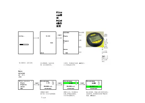
KLIPPEL 测试系统的简单操作手册检查激光:Enter----Main menu 选择Displacement meter----选择D(对校准器第二格,距离复0)----激光对准第一格(距离显示在9.7mm-10.3mm之间)----激光对准第三格,距离显示在-9.7mm—10.3mm之间----OK固定喇叭,将雷射激光对准喇叭中间反射面(可用涂改液涂在雷射光束照射喇叭位置,增强反射强度,白色贴纸也可),距离调至绿灯及黄灯皆连续亮,不闪动,将连接线正确接上喇叭正负端子。
LPM小信号线性参数测试1.点选第一行黄色资料夹图示,点选“open project”, 然后点选“new folder”,输入文件名后按OK。
2.点选第一行蓝色测试图示(new operation),点选测试模式“LPM linearparameters”, 点先“LPM Logitech”设定,按OK。
3.点选第一行灰色喇叭图示“properties”,选“info可于name”栏重新命名,“comment”栏输入备注说明。
然后点“Driver”,于“Diaphragm Area”栏输入有效振动面积(cm2),或于“Diameter”栏输入有效振动直径(cm),于“Material of voice coil”点音圈材质。
在于“Power”栏,输入额定功率(W),额定阻抗(ohm),按OK确认,按Close关闭。
4.点选第一行绿色启动图示开始测试。
结果可以得下列小信号线性参数Electrical ParametersRe electrical voice coil resistance at DC 直流电阻Le frequency independent part of voice coil inductanceL2 para-inductance of voice coilR2 electrical resistance due to eddy current lossesCmes electrical capacitance representing moving massLces electrical inductance representing driver complianceRes resistance due to mechanical lossesFs driver resonance frequency 共振频率Mechanical Parameters(using laser)Mms mechanical mass of driver diaphragm assembly Including air load and voice coil 有效振动质量(含空气负载)Mmd mechanical mass of voice coil and diaphragm without Air load 有效振动质量(不含空气负载)Rms mechanical resistance of total-driver lossesCms mechanical compliance of driver suspension 顺性Kms mechanical stiffness of driver suspension 钢性Bl force factor (Bl product) 磁力因数Lambdas suspension creep factorLoss factorsQtp total Q-factor considering all lossesQms mechanical Q-factor of driver in free air 机械阻尼因数Qes electrical Q-factor of driver in free air 电气阻尼系数Qts total Q-factor considering Re and Rms only 总阻尼系数Vas equivalent air volume of suspensionn0 reference efficiency (2 pi-radiation using Re)效率Lm sound pressure level 直流电阻活塞范围参考灵敏度Rmse Z root-mean-square fitting error of driver impedance Z(f)Rmse Hx root-mean-square fitting error of transfer function Hx(f)Series resistor resistance of series resistorSd diaphragm area 输入有效振动面积注:检查测试数据是否正确●点击“Table Linear Parameters” rmse Z 和rmse Hx 值都需小于4%●点击“Table Signal Characteristics” I SNR+D 值需大于20dB若喇叭失真明显高于杂讯,FO附近失真超过-20dB (10%),则将鼠标移至左上角视窗中代表本次测试的蓝色图示,击右键,点“Properties”,选Stimilus,于V oltage 栏将测试电压改小,再测一遍。


K750在使用前请详细阅读这些说明,并在充分了解动力切割机后才可开始使用。
Chinese警告! 动力切割机带危险性!不小心或不正确的使用方式会造成操作者或其他人员严重或者致命性伤害。
在使用前请详细阅读这些说明,并在充分了解动力切割机后才可开始使用。
在整个操作过程中,请配戴:•保护头盔•听觉保护设备•护目镜或覆面•通气口罩本产品符合适用的欧盟指令。
警告! 切割时会产生许多灰尘,可能导致吸入性伤害。
请使用经过检验合格的通气口罩。
避免吸入油气及废气。
确保有良好的通风设备。
警告! 切割锯片产生的火花,会引起汽油(天然气)、木材、干草等易燃物著火。
对环境的噪音释放遵照欧盟制订的指引。
本机的排放标准在《技术资料》篇和产品标签上有详细说明。
进行任何检查或者维修之前,把停止开关扳到《STOP》的位置上,以关掉引擎。
务必随时穿戴经过检验合格的保护手套。
必须经常清理。
定期检查。
务必配戴护目镜或覆面。
符号解说操作位置。
停止,复位弹簧位于操作位置。
停止于固定位置。
其它符号/标识是指特定市场上的专用合格证要求。
动力切割机上的符号:2 - Chinese目录目录符号解说符号解说 (2)目录目录 (3)零件组图示说明动力切割机上的零件组图示说明 (4)安全须知在使用新的动力切割机以前应采取的步骤 (5)人身防护配备 (5)动力切割机的安全设备 (6)动力切割机安全设备的检查、维修和保养 (7)一般安全须知 (8)一般工作须知 (9)切割锯片 (11)组装检查驱动轴和凸缘垫片 (13)安装切割锯片 (13)切割锯片的锯片防护罩 (13)燃油的处理燃油 (14)加油 (14)启动与停止启动与停止 (15)维修调整驱动皮带 (16)更换驱动皮带 (16)皮带滑轮与离合器 (16)化油器 (16)燃油滤清器 (17)空气滤清器 (17)启动器 (18)火花塞 (19)冷却系统 (19)消音器 (19)一般的维修说明 (20)技术资料切割设备 (21)EC 一致性声明 (22)Chinese - 3动力切割机上的零件组图示说明1 前侧把手2 水龙头3 警告标识4 空气滤清器外壳5 汽缸罩6 阻风门7 油门锁8 油门控制9 启动油门锁10 停止开关11切断 OilGuard 功能 (K750 OilGuard)12 启动器把手13 启动器14 消音器15 油箱16 自动解压阀17 切割锯片的锯片防护罩18 调整防护罩19 皮带保护罩20 带滤清器的水接头21 切割臂22 铭牌23 皮带张紧装置24 切割头25 切割锯片26 万用扳手27 操作手册零件组图示说明4 - ChineseChinese - 5在使用新的动力切割机以前应采取的步骤。

REFERENCE PREMIERE SUBWOOFERSRP-1000SW RP-1200SW RP-1400SW RP-1600SWWe want your new speaker system to look as good as it did leaving the factory! Please check promptly for any transit damage. Carefully unpack your new speaker system and verify the components against the packing list. In extreme circumstances, items may have become damaged in transit. If any damage is discovered, notify the delivery service and dealer where the system was purchased. Make a request for inspection, and follow their instructions for evaluation. Be sure to keep the product’s original shipping carton.INSPECTIONCONNECTIONS AND CONTROLSCAUTION: Ensure that the subwoofer is unplugged from the AC wall outletbefore making any connections.“LINE IN” Connection - Most of today’s surround receivers (and pre-amplifiers) have a line level subwoofer output labeled Subwoofer Pre Out, Sub Out, SW Out, etc. If you have this output, connect one end of a subwoofer cable to it and connect the other end of the cable into the subwoofer line input labeled L/LFE. This connection allows the subwoofer to operate with both music and surround sound movies (refer to your receiver manual). In absence of a subwoofer output on your receiver, as an alternative hookup, you can connect Left and Right channel Pre-Amp Outputs from your receiver (if provided) to the L/LFE and R inputs on the subwoofer.WA-2 Port Connection - For wireless connectivity of your new Klipsch Reference Premiere subwoofer, the optional WA-2 Wireless subwoofer kit is available. The WA-2 will only operate with select Klipsch, Energy, Mirage and Jamo brand subwoofers that have a “WA Port” input. The WA-2 is a 2.4 GHz product designed to wirelessly transmit a signal up to a 50 foot radius. See for more details.Level - If your subwoofer is connected to a Subwoofer Output of a surround receiver, first set the subwoofer volume level control in the receiver to the “half way” or “0 dB” position. Then increase the volume (or gain) of the subwoofer up until the subwoofer’s volume level matches the output of your main speakers. After this setup is completed, the volume control on your system’s main amplifier or pre-amplifier will be the volume control for both your subwoofer and speakers together. If your subwoofer is connected to the L/R Pre-Amp Outputs of a receiver there will be no subwoofer volume in that receiver to set before setting the subwoofer’s gain control.“LOWPASS” Control - The crossover point chosen determines where low bass frequencies are “handed off” from the speakers to the subwoofer. If setting the crossover point in the receiver, turn the Lowpass Filter knob on the subwoofer to the farthest point right (160Hz). Set the crossover point based on the size of the main left/right speakers you are using in the system. As a general rule, for larger, floorstanding speakers, set the crossover point between 50Hz-90Hz. If using small bookshelf or “satellite” speakers forthe mains, set the crossover point between 90Hz-150Hz. The smaller the speaker, the higher the setting until the bass frequencies blend well between the speakers and your subwoofer once your system is completely hooked up. If your receiver does not have a crossover point setting, set the Lowpass Filter on the subwoofer instead within the same recommended settings (see receiver manual for additional speaker setup info).“PHASE” 0/180 - This control is used to acoustically match the subwoofer’s output to your main speakers. Select the position, either 0° or 180°, in which your subwoofer has more output at the listening position.“POWER” AUTO/ON/OFF - When this switch is in the “ON/AUTO/STANDBY” position, the subwoofer will automatically turn “on” when it senses a signal. It will automatically go into “standby mode” after 15-20 minutes with no signal. When this switch is in the “OFF” position, the subwoofer will remain “off” until the switch is manually turned back to the “ON/AUTO/STANDBY” position. Power LED indicator - Located on the front baffle, this LED indicates the operating status of the built-in amplifier. The LED will light green whenthe amplifier is on and receiving a signal. If the LED is dark and not lit, the amplifier is off. For more information on the controls mentioned in this manual and on bass management, see your dealer or visit Your subwoofer has a durable vinyl finish that should only requiredry dusting or cleaning with a dry cloth. Avoid the use of abrasive orsolvent-based cleaners and harsh detergents. The brush attachment ofyour vacuum should remove any dust from your subwoofer enclosure.CARE AND CLEANINGRegister your product online at /register • Keep up-to-date on new products and promotions.• Your personal information will never be resold.• This registration information is not used forwarranty purposes.Please retain your receipt for warranty claims.PRODUCT REGISTRATIONCAISSONS DE GRAVES REFERENCE PREMIERENous voulons que votre nouvelle enceinte soit aussi belle qu’à sa sortie de l’usine ! Veuillez vérifier sans attendre qu’elle n’a pas été endommagée lors du transport. Déballez soigneusement votre nouvelle enceinte et vérifiez que les composants correspondent à la liste fournie. Dans des cas extrêmes, il est possible que des articles aient été endommagés au cours du transport.Si tel est le cas, avisez le livreur et le revendeur auprès duquel vous avez acheté le système. Faites une demande d’inspection, et suivez leurs instructions pour l’évaluation. Veillez à conserver le carton d’emballage d’origine du produit.INSPECTIONRP-1000SW RP-1200SW RP-1400SW RP-1600SWBRANCHEMENTS ET RÉGLAGESATTENTION : Veillez à ce que le caisson de graves soit débranché de la prise murale avant d’effectuer tout raccordement.Branchement d’entrée ligne (« LINE IN ») - La plupart des récepteurs(et préamplificateurs) surround d’aujourd’hui ont une sortie de niveau depréamplification pour caisson de graves intitulée Subwoofer Pre Out, Sub Out, SW Out, etc. Si vous disposez de cette sortie, branchez-y une extrémité d’un câble pour caisson de graves, et insérez l’autre extrémité du câble dans l’entrée de ligne du caisson de graves intitulée L/LFE. Ce branchement permet au caissonde graves de fonctionner aussi bien avec de la musique qu’avec des films en son surround (reportez-vous au manuel de votre récepteur). En l’absence d’une sortie pour caisson de graves sur votre récepteur, vous pouvez raccorder les sortiespréamplifiées des voies de gauche et de droite de votre récepteur (si disponibles) aux entrées L/LFE (Gauche/LFE) et R (Droite) du caisson de graves.Branchement au port WA-2 - Pour une connectivité sans fil de votre nouveau caisson de graves Klipsch Reference Premiere, le WA-2 est disponible en option. Le WA-2 fonctionnera uniquement avec certains caissons de graves de marque Klipsch, Energy, Mirage ou Jamo qui disposent d’une entrée intitulée « WA Port ». Le WA-2 est un produit de 2,4 GHz conçu pour transmettre un signal sans fil dans un rayon de 15 mètres. Consultez pour plus de détails.Réglage du gain (« LEVEL ») - Si votre caisson de graves est connecté à la sortie « Subwoofer » d’un récepteur surround, réglez d’abord le volume du caisson de graves sur la position « médiane » ou « 0 dB » du récepteur. Ensuite, augmentez le volume (ou le gain) du caisson de graves jusqu’à ce que la puissance sonore diffusée par le caisson de graves corresponde à celle de vos enceintes principales. Une fois ce réglage terminé, le bouton de volume de l’amplificateur ou dupréamplificateur de votre système assurera à la fois le réglage du volume de votre caisson de graves et de vos enceintes. Si votre caisson de graves est connecté aux sorties préamplifiées gauche/droite (L/R) d’un récepteur ou branché via la connexion à haut niveau aux bornes d’enceintes du récepteur, aucun réglage de volume du caisson de graves n’est nécessaire au niveau de ce récepteur avant de régler le contrôle de gain du caisson de graves. Réglage du filtre passe-bas (« LOWPASS ») - La fréquence de coupure choisiedétermine le point auquel les basses fréquences sont « transférées » des enceintes au caisson de graves. Pour régler la fréquence de coupure à partir du récepteur, tournez le bouton du filtre passe-bas (Lowpass Filter) du caisson de graves au maximum vers la droite (160 Hz). Réglez la fréquence de coupure en fonction dela taille des enceintes gauche/droite principales que vous utilisez avec le système. En règle générale, pour des enceintes de grande taille, de type colonne, réglezla fréquence de coupure entre 50 et 90 Hz. Si vous utilisez comme enceintes principales des enceintes de type bibliothèque ou satellite, réglez la fréquencede coupure entre 90 et 150 Hz. Plus l’enceinte est petite, plus le réglage doit être élevé pour que les basses fréquences se complètent harmonieusement entre les enceintes et votre caisson de graves une fois votre système entièrement installé. Si votre récepteur ne dispose pas d’un réglage de fréquence de coupure, réglezle filtre passe-bas (Lowpass Filter) du caisson de graves en suivant les mêmes recommandations (consultez le manuel du récepteur pour des renseignements supplémentaires concernant l’installation des enceintes).« PHASE » 0/180 - Ce réglage est utilisé pour ajuster le niveau acoustique du caisson de graves à vos enceintes principales. Sélectionnez la position (0° ou 180°) pour laquelle votre caisson de graves produit davantage de puissance à la position d’écoute.MISE SOUS TENSION (« POWER ») AUTO/ON/OFF - Lorsque ce commutateur est en position « ON », le caisson de graves reste en permanence sous tension. Lorsque ce commutateur est en position « AUTO », le caisson de graves se met automatiquement en marche dès la détection d’un signal. Il passe en mode veilleaprès 15-20 minutes sans signal. Lorsque le commutateur est en position « OFF »,le caisson de graves reste éteint tant que l’interrupteur d’alimentation est en position « ON » ou « AUTO » ou « STANDBY »Témoin de mise sous tension - Situé sur le baffle avant, ce témoin indique l’état opérationnel de l’amplificateur intégré. Le témoin est allumé en vert lorsquel’amplificateur est sous tension et reçoit un signal. Si le témoin n’est pas allumé,l’amplificateur est hors tension. Pour plus de renseignements sur les réglages mentionnés dans ce manuel et sur la gestion des graves, adressez-vous à votre revendeur ou consultez La finition vinyle résistante de votre caisson de graves ne nécessite qu’un dépoussiérage ou un nettoyage au chiffon sec. Évitez d’utiliser des produits de nettoyage abrasifs ou à base de solvant ainsi que des détergents agressifs. La brosse de votre aspirateur devrait être suffisante pour nettoyer la poussière de votre caisson de graves.ENTRETIEN ET NETTOYAGEEnregistrez votre produit en ligne à /register • Restez informé des nouveaux produits et des promotions.• Vos informations personnelles ne seront jamais revendues.• Ces informations d’enregistrement ne sont pas utilisées à des fins de garantie.Veuillez conserver votre reçu pour toute réclamation au titre de la garantie.ENREGISTREMENT DU PRODUITREFERENCE PREMIERE-SUBWOOFERWir wollen sicherstellen, dass Ihr neues Lautsprechersystem fabrikneu aussieht! Prüfen Sie bitte gleich, ob etwaige Transportschäden vorliegen. Packen Sie Ihr neues Lautsprechersystem sorgfältigaus und vergleichen Sie die Komponenten mit der Packliste. In Extremfällen könnten Teile während des Transports beschädigt worden sein.Falls Schäden festgestellt werden, müssen Sie die Speditionund den Fachhändler benachrichtigen, bei dem Sie das System gekauft haben. Verlangen Sie eine Inspektion und folgen Sie den Bewertungsanweisungen. Werfen Sie den Lieferkarton des Produkts nicht weg.INSPEKTIONRP-1000SW RP-1200SW RP-1400SW RP-1600SWANSCHLÜSSE UND REGLERACHTUNG: Stellen Sie vor der Herstellung von Anschlüssen sicher, dass der Subwoofer nicht an eine Steckdose angeschlossen ist.…LINE IN“-Anschluss – Heutzutage verfügen die meisten Surround-Receiver (und Vorverstärker) über einen Line-Level-Subwooferausgang, der als Subwoofer Pre Out, Sub Out, SW Out etc. bezeichnet wird. Wenn dieser Ausgang vorhanden ist, verbinden Sie ein Ende des Subwooferkabels damit und das andere Ende des Kabels an den Subwoofereingang L/LFE. Dadurch kann Ihr Subwoofer sowohl für Musik als auch Surroundsound-Filme eingesetzt werden (nähere Hinweise finden Sie im Handbuch Ihres Receivers). Falls Ihr Receiver keinen Subwooferausgang besitzt, können Sie auch die linken und rechten Vorverstärkerausgänge des Receivers (falls vorhanden) mit dem L/LFE- und R Eingang am Subwoofer verbinden.Anschluss über WA-2-Port - Für den drahtlosen Anschluss Ihres neuen Klipsch-Subwoofers Reference Premiere steht der optionale WA-2 zur Verfügung. Der WA-2 funktioniert nur bei bestimmten Subwoofern der Marken Klipsch, Energy, Mirage und Jamo, die einen als …WA Port“ markierten Eingang besitzen. Der WA-2 ist ein 2,4-GHz-Produkt, das problemlos ein drahtloses Signal in einem Radius von bis zu 15 m ausstrahlt. Weitere Details finden Sie auf .Verstärkungsregler (LEVEL) – Wenn Ihr Subwoofer an den Subwooferausgang eines Surroundsound-Receivers angeschlossen ist, stellen Sie den Subwooferlautstärkeregler des Receivers zunächst auf die mittlere (0 dB) Position. Dann erhöhen Sie die Lautstärke (oder den Verstärkungsfaktor) des Subwoofers, bis der Lautstärkepegel des Subwoofers dem Ihrer Hauptlautsprecher entspricht. Nach Beendigung der Anpassung dient der Lautstärkeregler am Hauptverstärker Ihres Systems bzw. am Vorverstärker als gemeinsamer Lautstärkeregler für den Subwoofer und die Lautsprecher. Wenn Ihr Subwoofer an die linken und rechten Vorverstärkerausgänge eines Receivers angeschlossen ist oder wenn er über die High-Level-Verbindung an die Lautsprecherterminals des Receivers angeschlossen ist, muss am Receiver keine Subwooferlautstärke eingestellt werden, bevor der Verstärkungsfaktor des Subwoofers eingestellt wird. …LOWPASS“ (Tiefpass) – Der gewählte Crossover-Punkt bestimmt, wanntiefe Bassfrequenzen von den Lautsprechern an den Subwoofer …übergeben“ werden. Wenn Sie den Crossover-Punkt am Receiver einstellen, drehen Sie den Tiefpassfilter-Regler am Subwoofer ganz nach rechts (160 Hz). Stellen Sie den Crossover-Punkt entsprechend der Größe der im System verwendeten linken/ rechten Hauptlautsprecher ein. Als Faustregel gilt, dass man bei größeren Standlautsprechern den Crossover-Punkt zwischen 50 und 90 Hz einstellt. Wenn Sie kleinere Regallautsprecher oder Satellitenlautsprecher als Hauptlautsprecher verwenden, stellen Sie den Crossover-Punkt zwischen 90 und 150 Hz ein. Je kleiner der Lautsprecher, desto höher die Einstellung, bis die Bassfrequenzen nach der kompletten Einrichtung Ihres Systems nahtlos zwischen Lautsprechern und Subwoofer übergehen. Wenn Ihr Receiver keine Einstellung für den Crossover-Punkt besitzt, stellen Sie stattdessen den Tiefpassfilter am Subwoofer im Rahmen der gleichen empfohlenen Einstellungen ein (weitere Informationen zum Einrichten der Lautsprecher finden Sie im Handbuch des Receivers).…PHASE“ 0/180 – Mit diesem Regler passen Sie die Ausgabe Ihres Subwoofers akustisch an die Hauptlautsprecher an. Wählen Sie die Position (0° oder 180°), in der der Subwoofer an der Hörposition lauter klingt.…POWER“ AUTO/ON/OFF – Wenn der Schalter auf …ON/AUTO/STANDBY”steht, schaltet sich der Subwoofer bei Entdeckung eines Signals automatisch ein. Wenn kein Signal vorhanden ist, schaltet er in den Standby-Modus nach 20 Minuten automatisch. Wenn dieser Schalter auf …OFF“ steht, bleibt der Subwoofer ausgeschaltet, wenn der Netzschalter in der Position …OFF“ ist.LED-Netzanzeige – Diese LED an der vorderen Schallwand zeigt den Betriebsstatus des eingebauten Verstärkers. Die LED leuchtet grün auf, wenn der Verstärker eingeschaltet ist und ein Signal empfängt. Wenn die LED gar nicht aufleuchtet, ist der Verstärker ausgeschaltet. Weitere Informationen über die in diesem Handbuch erwähnten Regler und das Bass-Management können Sie von Ihrem Fachhändler oder auf erhalten.Ihr Subwoofer verfügt über eine dauerhafte Vinyl-Oberfläche, die nur mit einem trockenen Tuch abgestaubt oder gereinigt werden muss. Verwenden Sie keine Scheuer- oder Lösungsmittel oder scharfen Reinigungsmittel. Sie können Staub auf dem Subwoofergehäuse mit dem Bürstenaufsatz eines Staubsaugers entfernen.PFLEGE UND REINIGUNGRegistrieren Sie Ihr Produkt online unter /register • Dadurch werden Sie über neue Produkte und Sonderangebote informiert.• Ihre personenbezogenen Daten werden nie verkauft.• Diese Registrierungsdaten werden nicht zu Garantiezwecken verwendet.Bewahren Sie bitte Ihre Quittung auf, um die Garantie in Anspruch nehmen zu können.PRODUKTREGISTRIERUNGSUBWOOFERS REFERENCE PREMIEREDeseamos que su nuevo sistema de altavoces se vea tan bien como se veía cuando salió de la fábrica. Vea rápidamente si se han producido daños durante el transporte. Desempaque cuidadosamente sunuevo sistema de altavoces y vea si en el paquete vienen todos los componentes indicados en la lista de empaque. En circunstancias extremas, es posible que algunas piezas o componentes se hayan dañado en tránsito. Si descubre daños, notifique al servicio de entregas y al minorista donde compró el sistema. Solicite una inspección y siga las instrucciones de evaluación. Conserve la caja de cartón original de envío del producto.INSPECCIÓNRP-1000SW RP-1200SW RP-1400SW RP-1600SWCONEXIONES Y CONTROLESPRECAUCIÓN: Desenchufe el subwoofer del enchufe de corriente alterna de la pared antes de hacer conexiones.Conexión de entrada de línea (LINE IN). La mayoría de los receptores (y preamplificadores) surround de hoy en día tienen una salida de subwoofer de nivel de línea que dice Subwoofer Pre Out, Sub Out, SW Out, etc. Si su receptor (o preamplificador) tiene esta salida, conéctele un extremo de un cable de subwoofer y conecte el otro extremo del cable a la entrada de línea del subwoofer que diceL/LFE. Esta conexión le permite al subwoofer funcionar con música y películas de sonido surround (consulte el manual del receptor). Si no hay salida de subwoofer en el receptor, puede conectar alternativamente salidas de preamplificación de canal izquierdo y canal derecho desde el receptor (si las tiene) a la entrada R y la entrada L/LFE del subwoofer.Conexión de Puerto WA-2. Para propósitos de conectividad inalámbrica, su nuevo subwoofer Reference Premiere de Klipsch tiene WA-2 opcional. El WA-2 funciona sólo con ciertos subwoofers marca Klipsch, Energy, Mirage y Jamo con entrada de “puerto WA” en el panel trasero del amplificador (consulte el manual del propietario del subwoofer). El WA-2 es un producto de 2.4 GHz diseñado para transmitir una señal inalámbrica de 50 pies (15 m) de alcance radial.Hay más detalles en .Control de volumen (LEVEL). Si el subwoofer está conectado a la salida de subwoofer de un receptor surround, ponga primero el control de volumen del subwoofer del receptor “a la mitad” o en la posición “0 dB”. Luego aumente el volumen (es decir, la amplificación) del subwoofer hasta que corresponda a la salida de los altavoces principales. Después de hacer esta configuración, el control de volumen del amplificador o preamplificador principal del sistema será el control de volumen común del subwoofer y de los altavoces. Si el subwoofer está conectado a las salidas de preamplificación izquierda y derecha de un receptor, o está cableado a través de la conexión de alto nivel a las terminales de altavoz del receptor, en ese receptor no será necesario fijar el volumen de subwoofer antes de configurar el control de volumen del subwoofer.Control de pasabajas (LOWPASS). El punto de crossover determina el límite superior de las frecuencias que se pasan de los altavoces al subwoofer. Si se vaa fijar el punto de crossover en el receptor, gire la perilla del filtro de pasabajas del subwoofer al máximo a la derecha (160 Hz). Fije el punto de crossoversegún el tamaño de los altavoces principales izquierdo y derecho que tengael sistema. Como regla general, para altavoces grandes, de piso, fije el puntode crossover entre 50 Hz y 90 Hz. Si los altavoces principales son altavoces pequeños o altavoces satélite, fije el punto de crossover entre 90 Hz y 150 Hz. Mientras más pequeño sea el altavoz, más alto debe ser el ajuste hasta quelas frecuencias de bajos se combinen bien entre los altavoces y el subwooferuna vez que el sistema quede completamente cableado. Si el receptor no tiene ajuste del punto de crossover, fije el filtro de pasabajas del subwoofer según las mismas configuraciones recomendadas (consulte el manual del receptor si desea información adicional de configuración de altavoces).Fase (PHASE) 0/180. Este control se utiliza para hacer corresponderacústicamente la salida del subwoofer con la de los altavoces principales. Seleccione la posición, 0° o 180°, en la cual el subwoofer tenga el mayor rendimiento de bajos en la posición de audición.ENCENDIDO Y APAGADO (POWER ON/OFF). Cuando este interruptor estáen la posición ON/AUTO/STANDBY, el subwoofer se enciende automáticamenteal detectar una señal. Si pasan más de 20 minutos sin señal, el subwoofer entra automáticamente en modo de espera. Cuando este interruptor está en la posición OFF, el subwoofer permanece apagado mientras el interruptor de encendido y apagado (POWER ON/OFF) esté en la posición de apagado (OFF).Indicador LED de alimentación. Este LED está ubicado en el bafle delantero del subwoofer e indica el estado de funcionamiento del amplificador integrado. El LED se ilumina de color verde cuando el amplificador está encendido y recibiendo una señal. Si el LED está oscuro, no iluminado, el amplificador está apagado. Para obtener más información sobre los controles mencionados en este manual y sobre procesamiento de bajos, vea a su distribuidor o vaya a El subwoofer tiene un acabado de vinilo resistente que solamente requiere quitarle el polvo o limpiarlo con un paño seco. Evite losdetergentes fuertes y los limpiadores abrasivos o a base de solvente. El accesorio de cepillo de la aspiradora sirve para quitarle el polvo a la caja del subwoofer .CUIDADO Y LIMPIEZARegistre su producto en línea en /register• Klipsch lo mantendrá al día sobre nuevos productos y promociones.• Sus datos personales no se venderán nunca.• Esta información de registro no se utiliza para propósitos de garantía.Conserve su recibo para hacer las reclamaciones de garantía.REGISTRO DEL PRODUCTOSUBWOOFERS REFERENCE PREMIEREQueremos que seu novo sistema de caixas acústicas tenha sempre a aparência de novo! Por isso, inspecione-o imediatamente para verificar se sofreu algum dano durante o transporte. Desembale com cuidado o novo sistema de caixas acústicas e verifique se foram enviados todos os componentes descritos na lista. Em circunstâncias extremas, alguns componentes podem sofrer danos durante o transporte. Nesse caso, avise a transportadora e o revendedor onde o sistema foi adquirido. Faça um pedido de inspeção e siga as instruções recebidas para avaliar os danos. Não descarte a caixa original utilizada para transportar o produto.INSPEÇÃORP-1000SW RP-1200SW RP-1400SW RP-1600SWCONEXÕES E CONTROLESCUIDADO: Certifique-se de que o subwoofer esteja desconectado da tomada antes de fazer qualquer conexão.Conexão “LINE IN” – A maioria dos receivers (e pré-amplificadores) surround atuais tem uma saída de subwoofer de nível de linha identificada com os dizeres Subwoofer Pre Out, Sub Out, SW Out, etc. Se o aparelho tiver este tipo desaída, conecte uma extremidade do cabo de subwoofer nela e conecte a outra extremidade na entrada de linha do subwoofer marcada L/LFE. Esta conexão permite que o subwoofer seja usado para reproduzir trilhas sonoras musicais ede filmes com som surround (consulte o manual do receiver). Como alternativa de conexão, se o receiver não tiver uma saída para subwoofer, é possível conectar as saídas dos canais esquerdo (Left) e direito (Right) para pré-amplificador do receiver (se existirem) à entrada esquerda L/LFE e R (Right) do subwoofer.Conexão da porta WA-2 - Para conectar o novo subwoofer Klipsch Reference Premiere sem fios, use o kit WA-2 opcional. O WA-2 só funciona com subwoofers específicos das marcas Klipsch, Energy, Mirage e Jamo que têm uma entrada “WA Port” (Porta WA). O WA-2 é um produto de 2,4 GHz projetado para transmitir sinais sem fio em um raio de até 15 metros. Acesse o site para obter mais detalhes.Controle “LEVEL” – Se o subwoofer estiver conectado a uma saída para subwoofer de um receiver surround, ajuste primeiro o controle do volume do subwoofer no receiver para “metade”, ou seja, posição de “0 dB”. Em seguida, aumente o volume (ou ganho) do subwoofer até que o nível de volume do subwoofer corresponda à saída das caixas acústicas principais. Depois de completar este ajuste, o controle do volume no amplificador principal do sistema ou do pré-amplificador controlará o volume do subwoofer e das caixas acústicas. Se o subwoofer estiver conectado às saídas de pré-amplificador esquerda/direita de um receiver ou estiver conectado através da conexão High-Level dos terminais de caixas acústicas do receiver, não será necessário fazer qualquer ajuste no volume do subwoofer no receiver antes de ajustar o controle de ganho do subwoofer. Controle “LOWPASS” – O ponto de crossover escolhido determina onde asfrequências passa baixas são “transferidas” das caixas acústicas para o subwoofer. Se for ajustar o ponto de crossover no receiver, gire o botão de controle do filtro passa baixas (Lowpass) todo para a direita (160 Hz). Ajuste o ponto de crossover com base no tamanho das caixas acústicas principais esquerda/direita usadas no sistema. Como regra geral, para caixas acústicas de piso maiores, ajuste o ponto de crossover entre 50 e 90 Hz. Se estiver usando caixas acústicas de estante ou “satélite” como unidades principais, ajuste o ponto de crossover entre 90 e 150 Hz. Quanto menor a caixa acústica, maior o ajuste, até haver uma boa combinação das frequências mais baixas (graves) entre as caixas acústicas e o subwoofer quando todas as conexões do sistema estiverem feitas. Se o receiver não tiver um controle de ajuste do ponto de crossover, ajuste o filtro passa baixas (Lowpass) do subwoofer com os mesmos níveis recomendados (consulte o manual do receiver para obter mais informações de configuração das caixas acústicas).“PHASE” 0/180 – Este controle é usado para estabelecer a correlação acústica entre a saída do subwoofer e a das caixas acústicas principais. Selecione a posição, 0° ou 180°, na qual o subwoofer tem melhor reprodução na posição ocupada pelo ouvinte.“POWER” AUTO/ON/OFF - Quando esta chave está na posição “ON/AUTO/ STANDBY”, o subwoofer liga automaticamente quando detecta um sinal e muda para o modo de espera automaticamente após 20 minutos de ausência de sinal. Quando esta chave está na posição “OFF”, o subwoofer fica desligado enquanto a chave “POWER” ON/OFF estiver na posição “OFF”.LED indicador de ativação - Localizado no sonofletor frontal, este LED indicao estado de funcionamento do amplificador integrado. O LED fica verde quandoo amplificador está ligado e recebendo um sinal. Se o LED estiver apagado, isto indica que o amplificador está desligado. Para obter mais informações sobre os controles mencionados neste manual e sobre os ajustes de controle de graves, consulte o revendedor ou acesse o site 。

QC 品质控制测试系统 - 线上终端测试C3版本:2.0特点效益• 在物理门限下非常快速地测量 • 高精度扫描技術• 简单门限计算,合格/不合格分类 • 自動檢測 Golden Unit – 标准参考件 • 自行開發的獨有Rub & Buzz 异音測試 (Meta Hearing 技术)• 自动重复生产线环境噪声检测 • T/S 參数 (Re, fs, Qts) • 阻抗, 频率响应 • 极性, 平均电平 • 闸性脈冲响应• 總諧波失真THD, 2nd – 5th 次失真,多音 • 驱动和悬边测试 • 線圈位置 - 毫米 • 悬边不平衡 – 百分比 % • 測試数據輸出工具 • 生產指数 (Cpk, Ppk) • 不同的操作级别(操作员、 品质控制工程师、程序员) • 高级編程版本 • 揚声器配对功具 • 自動檢測功放增益 • 測試報告产生器• 通过数字接口方便整合到生产装配线 • 中、英文操作手册特定的配置可能不包括上面列的所有特点提供100%的产品测试 确保产品的一致性比人耳听觉测试更加可靠 简易的直接的操作 生产线噪声免疫在生产进程中可以无缝整合 与Klippel R&D 分析仪系统兼容灵活可靠的解决方法满足不同 公司的需求高级编程语言提供不同编程要求应用扬声器 、耳机 、微声器 整個音頻系统 线上终端测试来料检查内容:总览 (2)硬件...............................................................................................................................................3 - 4 QC 軟件 (标準版本)....................................................................................................................5 - 7 操作模式.. (8)Rub & Buzz 异音....................................................................................错误!未定义书签。

Genotype quality control with plinkQCHannah Meyer2021-07-15ContentsIntroduction1 Per-individual quality control (2)Per-marker quality control (2)Clean data (2)Workflow2 Per-individual quality control (3)Per-marker quality control (6)Create QC-ed dataset (8)Step-by-step8 Individuals with discordant sex information (8)Individuals with outlying missing genotype and/or heterozygosity rates (9)Related individuals (10)Individuals of divergent ancestry (11)Markers with excessive missingness rate (12)Markers with deviation from HWE (13)Markers with low minor allele frequency (14)References15 IntroductionGenotyping arrays enable the direct measurement of an individuals genotype at thousands of markers. Subsequent analyses such as genome-wide association studies rely on the high quality of these marker genotypes.Anderson and colleagues introduced a protocol for data quality control in genetic association studies heavily based on the summary statistics and relatedness estimation functions in the PLINK software[1].PLINK is a comprehensive,open-source command-line tool for genome-wide association studies(GWAS)and population genetics research[2].It’s main functionalities include data management,computing individual-and marker-level summary statistics,identity-by-state estimation and association analysis.Integration with R is achieved through its R plugin or PLINK/SEQ R Package[4].While the plugin is limited to operations yielding simple genetic marker vectors as output,the PLINK/SEQ R Package is limited in the functionalities it can access.plinkQC facilitates genotype quality control for genetic association studies as described by[1].It wraps around plink basic statistics(e.g.missing genotyping rates per individual,allele frequencies per genetic marker)and relationship functions and generates a per-individual and per-marker quality control report. Individuals and markers that fail the quality control can subsequently be removed with plinkQC to generatea new,clean dataset.Removal of individuals based on relationship status is optimised to retain as many individuals as possible in the study.plinkQC depends on the PLINK(version1.9),which has to be manually installed prior to the usage of plinkQC.It assumes the genotype have already been determined from the original probe intensity data of the genotype array and is available in plink format.Note:PLINK2.0is still in alpha status with many re-implementations and updates,including outputfile changes.While these changes are ongoing,plinkQC will rely on users using PLINK1.9.I will monitor PLINK 2.0changes and check compatibility with plinkQC.If users require specific PLINK2.0output,I recommend using the Step-by-Step approach described below and manually saving to the outputfiles expected from PLINK1.9.The protocol is implemented in three main functions,the per-individual quality control(perIndividualQC), the per-marker quality control(perMarkerQC)and the generation of the new,quality control dataset (cleanData):Per-individual quality controlThe per-individual quality control with perIndividualQC wraps around these functions:(i)check_sex:for the identification of individuals with discordant sex information,(ii)check_heterozygosity_and_missingness: for the identification of individuals with outlying missing genotype and/or heterozygosity rates,(iii) check_relatedness:for the identification of related individuals,(iv)check_ancestry:identification of individuals of divergent ancestry.Per-marker quality controlThe per-marker quality control with perMarkerQC wraps around these functions:(i)check_snp_missingnes: for the identifying markers with excessive missing genotype rates,(ii)check_hwe:for the identifying markers showing a significant deviation from Hardy-Weinberg equilibrium(HWE),(iii)check_maf:for the removal of markers with low minor allele frequency(MAF).Clean datacleanData takes the results of perMarkerQC and perIndividualQC and creates a new dataset with all individuals and markers that passed the quality control checks.WorkflowIn the following,genotype quality control with plinkQC is applied on a small example dataset with200 individuals and10,000markers(provided with this package).The quality control is demonstrated in three easy steps,per-individual and per-marker quality control followed by the generation of the new dataset. In addition,the functionality of each of the functions underlying perMarkerQC and perIndividualQC is demonstrated at the end of this vignette.package.dir<-find.package( plinkQC )indir<-file.path(package.dir, extdata )qcdir<-tempdir()name<- datapath2plink<-"/Users/hannah/bin/plink"Per-individual quality controlFor perIndividualQC,one simply specifies the directory where the data is stored(qcdir)and the prefix of the plinkfiles(i.e.prefix.bim,prefix.bed,prefix.fam).In addition,the names of thefiles containing information about the reference population and the merged dataset used in check_ancestry have to be provided:refSamplesFile,refColorsFile and prefixMergedDataset.Per default,all quality control checks will be conducted.In addition to running each check,perIndividualQC writes a list of all fail individual IDs to the qcdir.These IDs will be removed in the computation of the perMarkerQC.If the list is not present,perMarkerQC will send a message about conducting the quality control on the entire dataset.NB:To reduce the data size of the example data in plinkQC,data.genome has already been reduced to the individuals that are related.Thus the relatedness plots in C only show counts for related individuals only. NB:To demonstrate the results of the ancestry check,the required eigenvectorfile of the combined study and reference datasets have been precomputed and for the purpose of this example will be copied to the qcdir. In practice,the qcdir will often be the same as the indir and this step will not be required.file.copy(file.path(package.dir, extdata/data.HapMapIII.eigenvec ),qcdir)#>[1]TRUEperIndividualQC displays the results of the quality control steps in a multi-panel plot.fail_individuals<-perIndividualQC(indir=indir,qcdir=qcdir,name=name,refSamplesFile=paste(indir,"/HapMap_ID2Pop.txt",sep=""),refColorsFile=paste(indir,"/HapMap_PopColors.txt",sep=""),prefixMergedDataset="data.HapMapIII",path2plink=path2plink,do.run_check_ancestry=FALSE,interactive=TRUE,verbose=TRUE)overviewperIndividualQC depicts overview plots of quality control failures and the intersection of quality control failures with ancestry exclusion.overview_individuals<-overviewPerIndividualQC(fail_individuals,interactive=TRUE)Per-marker quality controlperMarkerQC applies its checks to data in the specified directory(qcdir),starting with the specified prefix of the plinkfiles(i.e.prefix.bim,prefix.bed,prefix.fam).Optionally,the user can specify different thresholds for the quality control checks and which check to conduct.Per default,all quality control checks will be conducted.perMarkerQC displays the results of the QC step in a multi-panel plot.fail_markers<-perMarkerQC(indir=indir,qcdir=qcdir,name=name,path2plink=path2plink,verbose=TRUE,interactive=TRUE,showPlinkOutput=FALSE)overviewPerMarkerQC depicts an overview of the marker quality control failures and their overlaps. overview_marker<-overviewPerMarkerQC(fail_markers,interactive=TRUE)Create QC-ed datasetAfter checking results of the per-individual and per-marker quality control,individuals and markers that fail the chosen criteria can automatically be removed from the dataset with cleanData,resulting in the new dataset qcdir/data.clean.bed,qcdir/data.clean.bim,qcdir/data.clean.fam.For convenience,cleanData returns a list of all individuals in the study split into keep and remove individuals.Ids<-cleanData(indir=indir,qcdir=qcdir,name=name,path2plink=path2plink,verbose=TRUE,showPlinkOutput=FALSE)Step-by-stepIndividuals with discordant sex informationThe identification of individuals with discordant sex information helps to detect sample mix-ups and samples with very poor genotyping rates.For each sample,the homozygosity rates across all X-chromosomal genetic markers are computed and compared with the expected rates(typically$<$0.2for females and$>$0.8for males).For samples where the assigned sex(PEDSEX in the.famfile)contradicts the sex inferred from the homozygosity rates(SNPSEX),it should be checked that the sex was correctly recorded(genotyping often occurs at different locations as phenotyping and misrecording might occur).Samples with discordant sex information that is not accounted for should be removed from the study.Identifying individuals with discordant sex information is implemented in check_sex.Itfinds individuals whose SNPSEX!=PEDSEX. Optionally,an extra data.frame with sample IDs and sex can be provided to double check if external and PEDSEX data(often processed at different centers)match.If a mismatch between PEDSEX and SNPSEX was detected,by SNPSEX==Sex,PEDSEX of these individuals can optionally be updated.check_sex depicts the X-chromosomal heterozygosity(SNPSEX)of the samples split by their(PEDSEX).fail_sex<-check_sex(indir=indir,qcdir=qcdir,name=name,interactive=TRUE,verbose=TRUE,path2plink=path2plink)Individuals with outlying missing genotype and/or heterozygosity ratesThe identification of individuals with outlying missing genotype and/or heterozygosity rates helps to detectsamples with poor DNA quality and/or concentration that should be excluded from the study.Typically,individuals with more than3-7%of their genotype calls missing are removed.Outlying heterozygosity ratesare judged relative to the overall heterozygosity rates in the study,and individuals whose rates are morethan a few standard deviations(sd)from the mean heterozygosity rate are removed.A typical qualitycontrol for outlying heterozygosity rates would remove individuals who are three sd away from the mean rate.Identifying related individuals with outlying missing genotype and/or heterozygosity rates is implemented in check_het_and_miss.Itfinds individuals that have genotyping and heterozygosity rates that fail the set thresholds and depicts the results as a scatter plot with the samples’missingness rates on x-axis and theirheterozygosity rates on the y-axis.fail_het_imiss<-check_het_and_miss(indir=indir,qcdir=qcdir,name=name,interactive=TRUE,path2plink=path2plink)Related individualsDepending on the future use of the genotypes,it might required to remove any related individuals from the study.Related individuals can be identified by their proportion of shared alleles at the genotyped markers(identity by descend,IBD).Standardly,individuals with second-degree relatedness or higher will be excluded.Identifying related individuals is implemented in check_relatedness.Itfinds pairs of samples whose proportion of IBD is larger than the specified highIBDTh.Subsequently,for pairs of individual that do not have additional relatives in the dataset,the individual with the greater genotype missingness rate is selected and returned as the individual failing the relatedness check.For more complex family structures,the unrelated individuals per family are selected(e.g.in a parents-offspring trio,the offspring will be marked as fail,while the parents will be kept in the analysis).NB:To reduce the data size of the example data in plinkQC,data.genome has already been reduced to the individuals that are related.Thus the relatedness plots in C only show counts for related individuals only. exclude_relatedness<-check_relatedness(indir=indir,qcdir=qcdir,name=name,interactive=TRUE,path2plink=path2plink)Individuals of divergent ancestryThe identification of individuals of divergent ancestry can be achieved by combining the genotypes of the study population with genotypes of a reference dataset consisting of individuals from known ethnicities(for instance individuals from the Hapmap or1000genomes study[5]).Principal component analysis on this combined genotype panel can be used to detect population structure down to the level of the reference dataset (for Hapmap and1000Genomes,this is down to large-scale continental ancestry).Identifying individuals of divergent ancestry is implemented in check_ancestry.Currently,check ancestry only supports automatic selection of individuals of European descent.It uses information from principal components1and2tofind the center of the European reference samples.All study samples whose euclidean distance from the centre falls outside a specified radius are considered non-European.check_ancestry creates a scatter plot of PC1 versus PC2color-coded for samples of the reference populations and the study population.exclude_ancestry<-check_ancestry(indir=indir,qcdir=qcdir,name=name,refSamplesFile=paste(indir,"/HapMap_ID2Pop.txt",sep=""),refColorsFile=paste(indir,"/HapMap_PopColors.txt",sep=""),prefixMergedDataset="data.HapMapIII",path2plink=path2plink,run.check_ancestry=FALSE,interactive=TRUE)Markers with excessive missingness rateMarkers with excessive missingness rate are removed as they are considered unreliable.Typically,thresholds for marker exclusion based on missingness range from1%-5%.Identifying markers with high missingness rates is implemented in snp_missingness.It calculates the rates of missing genotype calls and frequency for all variants in the individuals that passed the perIndividualQC.fail_snpmissing<-check_snp_missingness(indir=indir,qcdir=qcdir,name=name,interactive=TRUE,path2plink=path2plink,showPlinkOutput=FALSE)Markers with deviation from HWEMarkers with strong deviation from HWE might be indicative of genotyping or genotype-calling errors.As serious genotyping errors often yield very low p-values(in the order of10−50),it is recommended to choose a reasonably low threshold to avoidfiltering too many variants(that might have slight,non-critical deviations). Identifying markers with deviation from HWE is implemented in check_hwe.It calculates the observed and expected heterozygote frequencies per SNP in the individuals that passed the perIndividualQC and computes the deviation of the frequencies from Hardy-Weinberg equilibrium(HWE)by HWE exact test. fail_hwe<-check_hwe(indir=indir,qcdir=qcdir,name=name,interactive=TRUE,path2plink=path2plink,showPlinkOutput=FALSE)Markers with low minor allele frequencyMarkers with low minor allele count are often removed as the actual genotype calling(via the calling algorithm) is very difficult due to the small sizes of the heterozygote and rare-homozygote clusters.Identifying markers with low minor allele count is implemented in check_maf.It calculates the minor allele frequencies for all variants in the individuals that passed the perIndividualQC.fail_maf<-check_maf(indir=indir,qcdir=qcdir,name=name,interactive=TRUE,path2plink=path2plink,showPlinkOutput=FALSE)References1.Anderson CA,Pettersson FH,Clarke GM,Cardon LR,Morris AP,Zondervan KT.Data quality control in genetic case-control association studies.Nature Protocols.2010;5:1564–73.doi:10.1038/nprot.2010.1162.Purcell S,Neale B,Todd-Brown K,Thomas L,Ferreira MAR,Bender D,et al.PLINK:a tool set for whole-genome association and population-based linkage analyses.The American Journal of Human Genetics. 2007;81:559–75.doi:10.1086/5197953.Chang CC,Chow CC,Tellier LC,Vattikuti S,Purcell SM,Lee JJ.Second-generation PLINK:rising to the challenge of larger and richer datasets.GigaScience.2015;4:7.doi:10.1186/s13742-015-0047-84.PLINK/SEQ.2014.Available:https:///plinkseq/index.shtml5.The International HapMap Consortium.A haplotype map of the human genome.Nature.2005;437: 1299–320.doi:10.1038/nature042266.The International HapMap Consortium.A second generation human haplotype map of over3.1million SNPs.Nature.2007;449:851.doi:10.1038/nature062587.The International HapMap Consortium.Integrating common and rare genetic variation in diverse human populations.Nature.2010;467.doi:10.1038/nature092988.1000Genomes Project Consortium.An integrated map of structural variation in2,504human genomes. Nature.2015;526:75–81.doi:10.1038/nature153949.1000Genomes Project Consortium.A global reference for human genetic variation.Nature.2015;526: 75–81.doi:10.1038/nature15393。

THIS DOCUMENT CONTAINS INFORMATION THAT IS PROPRIETARY TO MOLEX ELECTRONIC TECHNOLOGIES, LLC AND SHOULD NOT BE USED WITHOUT WRITTEN PERMISSIONTHIS DOCUMENT CONTAINS INFORMATION THAT IS PROPRIETARY TO MOLEX ELECTRONIC TECHNOLOGIES, LLC AND SHOULD NOT BE USED WITHOUT WRITTEN PERMISSIONTHIS DOCUMENT CONTAINS INFORMATION THAT IS PROPRIETARY TO MOLEX ELECTRONIC TECHNOLOGIES, LLC AND SHOULD NOT BE USED WITHOUT WRITTEN PERMISSION1.0THIS DOCUMENT CONTAINS INFORMATION THAT IS PROPRIETARY TO MOLEX ELECTRONIC TECHNOLOGIES, LLC AND SHOULD NOT BE USED WITHOUT WRITTEN PERMISSION3.0THIS DOCUMENT CONTAINS INFORMATION THAT IS PROPRIETARY TO MOLEX ELECTRONIC TECHNOLOGIES, LLC AND SHOULD NOT BE USED WITHOUT WRITTEN PERMISSION4.4THIS DOCUMENT CONTAINS INFORMATION THAT IS PROPRIETARY TO MOLEX ELECTRONIC TECHNOLOGIES, LLC AND SHOULD NOT BE USED WITHOUT WRITTEN PERMISSION6.0THIS DOCUMENT CONTAINS INFORMATION THAT IS PROPRIETARY TO MOLEX ELECTRONIC TECHNOLOGIES, LLC AND SHOULD NOT BE USED WITHOUT WRITTEN PERMISSION6.2THIS DOCUMENT CONTAINS INFORMATION THAT IS PROPRIETARY TO MOLEX ELECTRONIC TECHNOLOGIES, LLC AND SHOULD NOT BE USED WITHOUT WRITTEN PERMISSION6.2THIS DOCUMENT CONTAINS INFORMATION THAT IS PROPRIETARY TO MOLEX ELECTRONIC TECHNOLOGIES, LLC AND SHOULD NOT BE USED WITHOUT WRITTEN PERMISSION6.3THIS DOCUMENT CONTAINS INFORMATION THAT IS PROPRIETARY TO MOLEX ELECTRONIC TECHNOLOGIES, LLC AND SHOULD NOT BE USED WITHOUT WRITTEN PERMISSION6.3THIS DOCUMENT CONTAINS INFORMATION THAT IS PROPRIETARY TO MOLEX ELECTRONIC TECHNOLOGIES, LLC AND SHOULD NOT BE USED WITHOUT WRITTEN PERMISSION7.0THIS DOCUMENT CONTAINS INFORMATION THAT IS PROPRIETARY TO MOLEX ELECTRONIC TECHNOLOGIES, LLC AND SHOULD NOT BE USED WITHOUT WRITTEN PERMISSIONTHIS DOCUMENT CONTAINS INFORMATION THAT IS PROPRIETARY TO MOLEX ELECTRONIC TECHNOLOGIES, LLC AND SHOULD NOT BE USED WITHOUT WRITTEN PERMISSION9.0THIS DOCUMENT CONTAINS INFORMATION THAT IS PROPRIETARY TO MOLEX ELECTRONIC TECHNOLOGIES, LLC AND SHOULD NOT BE USED WITHOUT WRITTEN PERMISSIONThe figure indicate inner lock type. However, the measurement method is same for friction lock type.THIS DOCUMENT CONTAINS INFORMATION THAT IS PROPRIETARY TO MOLEX ELECTRONIC TECHNOLOGIES, LLC AND SHOULD NOT BE USED WITHOUT WRITTEN PERMISSION12.0THIS DOCUMENT CONTAINS INFORMATION THAT IS PROPRIETARY TO MOLEX ELECTRONIC TECHNOLOGIES, LLC AND SHOULD NOT BE USED WITHOUT WRITTEN PERMISSION15. There is no influence in the product performance though discoloration might be generated in the resin THIS DOCUMENT CONTAINS INFORMATION THAT IS PROPRIETARY TO MOLEX ELECTRONIC TECHNOLOGIES, LLC AND SHOULD NOT BE USED WITHOUT WRITTEN PERMISSIONPico-Clasp 1.0 W-t-B Connectors Web PageTABLE OF CONTENTTHIS DOCUMENT CONTAINS INFORMATION THAT IS PROPRIETARY TO MOLEX ELECTRONIC TECHNOLOGIES, LLC AND SHOULD NOT BE USED WITHOUT WRITTEN PERMISSIONREVISIONDESCRIPTIONPICO-CLASP 1.0 WTB CONN SINGLE ROWLOW HALOGEN INNER LOCK GOLD PLATING 製品仕様書CHANGE NO. 691064REVISED BYPRAMODDATE 2022/01/06 DOC TYPEDOC TYPE DESCRIPTION DOC PART SERIES REV APPR BY MRAMAKRISHNA DATE 2022/01/06 PSPRODUCT SPECIFICATION WORD004 501330 29. At packaging, transportation and storing, avoid applying loads to connectors by handling, interference of connectors or piling-up packages. It could cause functional defect such as connector deformation or breakage.Operation: 30. Refer to the Application Specification (5013300000-AS PS 001) for details of connector handling instruction.31. When connectors are unmated, positive locks shall be released. (Applicable Positive Lock type)32. Please do the mating as much as possible to along to mating axis. At this time, positioning each side of external faces of receptacle housing and plug and push to mating until both connectors strikes each other (complete mating position). In the case of diagonal mating, touch with external faces with receptacle housing and plug under the angle of 10°lightly, and push to mating in order to avoid the connector break.33. Please do not do work that the load hangs in the connectors like the carrying of the substrate etc. with the connectors engages. There is a case where it causes the connectors damage etc.34. After mated the connectors, please do not allow the PCBs to apply pressure on the connectors in either the pitch direction, the span direction or rotational direction. It may cause damage to the connectors and may crack the soldering.35. This product is not designed for the mating and un-mating of the connectors to be performed under the condition of an active electrical circuit. It may cause a spark and product defect if the connectors are mated and unmated in this way.36. When un-mating connector, please ensure to hold wires all together lightly, and release the lock completely by attaching flat part of fingers to the lock and pushing the lock bar in case using the positive lock product. Then, please withdraw the receptacle housing slowly and straightly to the mating axial direction. Please avoid withdrawing diagonally and strongly. This may cause the damage of the connector. 37. Please do not deliberately deform the movable portion (the lock area and lance of plug housing) and terminals. It would lead to product failure.THIS DOCUMENT CONTAINS INFORMATION THAT IS PROPRIETARY TO MOLEX ELECTRONIC TECHNOLOGIES, LLC AND SHOULD NOT BE USED WITHOUT WRITTEN PERMISSION。

克朗斯灌装机操作手册 The manuscript was revised on the evening of 2021Manual of the Krones Aseptic line CC Xiamen Content内容Sterilization UHT / Bloc 3UHT杀菌系统/洁净空间Production preparation 6生产准备Production 14生产Type change over 16产品转换End of production 20生产结束Empty the disinfection bath 23清空盖槽CIP caustic and acid 26CIP碱酸洗N2 injector 29滴氮系统Manual of the Krones Aseptic lineKrones无菌生产线手册Sterilization UHT / BlocUHT杀菌系统/洁净空间MMA -> Programs程序 -> Program selection, general, U01Sterilization杀菌 -> Sterilization杀菌 -> Start开始Activating the step sequences, it is possible to follow the program 启动程序步骤,才有可能进行程序操作MMA -> Step sequences -> Step sequence general U01During sterilization, temperatures and flow is controlled by the PCS. These temperatures have to reach at least 121 °C minimum for 20 min.在杀菌(SIP)期间,温度以及流体的流量由PCS控制。
PCI / PCIEX1 / LPC/MiniPCI-E诊断卡KQCPET6-H V1使用说明书Ver:1.0-奇冠代码显示器主板基本信号指示灯信号驱动芯片工厂专用接口当插入PCI_E 插槽时固定机箱挡板螺丝孔(挡板可选配)PCI/PCIEX1/LPC/MiniPCI-E 诊断卡PCI 接口PCIEX1接口BIOS 代码与奇冠2位开放代码显示器LPC/MiniPCI-E接口座: 连接五口板、十字板、MiniPCI-E 板外接显示器座(可通过连线外接数码显示器,可选)当插入PCI 时固定机箱挡板螺丝孔BIOS 代码翻查按键当PCI 与PCIEX1插槽同时存在,请安装诊断卡于PCI 插槽当PCI 与PCIEX1插槽同时存在,请安装卡到对应的插槽,即PCI 介面插到PCI 插槽,PCI-E 介面插到PCI-E X1/X4/X8/X16接口上,特别注意:千万不要将PCI-E 接口插到PCI 插槽或AGP 等非PCI-E 槽使用,否则通电会烧卡或电脑.PCI/PCIEX1接口诊断卡使用注意诊断卡与主板PCI-Express x1当使用台式PCI-E接口,若为多插槽,请安装于PCIEX1_1,避免出现无法解码.(也可安装于PCI-Express x4、x8、x16插槽,注意有些主板仅PCI_E X1_1槽才有代码)LPC诊断和主板LPC-DEBUG接口使用于有LPC-Debug接口的主板,将诊断卡的LPC接口装置于主板DEBUG_PORT(不同主板对LPC-DEBUG接口的标识不尽相同,请用户仔细辨别)位置,同时将诊断卡主卡的P CI-E接口插到主板的PCI-E X1/X4/X8/X16插槽上使用.诊断卡—RUN信号灯•RUN灯只用极少部件,故自身故障率极低,且只需极少的主板插槽信号,故即使插到一个坏的插槽中虽无法走代码,或其它的所有指示灯都不亮,但该灯很有可能照常工作,您可根据:“只要此灯闪亮过,则证明主板运行过”的关键诊断结果助您分析下列问题:1.诊断卡自身的代码部分不良;2.您的这块诊断卡不能兼容被测主板;3.诊断卡插入的是一个坏的PCI或诊断卡连接的是坏接口;4.诊断卡没有插好或插脚脏或金属弹片生锈等原因造成与诊断卡接触不良;5.主板“死机”;6.主板正在执行与代码无关的程序。
MILLIPORESimplicity (185)个人专用超纯水机中文使用手册厦门莱胜科技有限公司2004年5月 V1.0(以英文原版手册为准)第一章:安装拆箱Simplicity TM系统包括(如附图1):A.纯水主机一套(Simplicity TM),内含3.5公升储水桶一只。
B.英文使用手册一本。
C.排气用(新的Simpak排气用)倒钩式连接头一只D.Simpak纯化管柱一组。
E.储水桶空气过滤器一只。
F.终端过滤器(POU)Simfilter一只。
安装储水桶(如附图2)A.将储水桶装水1.将储水桶上方的安全把手(locking handle)拉起到垂直位置(A)2.以安全把手将储水桶(B)提起3.以逆时针方向旋转1/4圈,打开储水桶上方的盖子(C)4.将储水桶装满经处理过的水(如:蒸馏水、去离子水、R O水或E l i x TM水)后,重新安装回主机,并且确认已将安全把手放回原来的位置(水平位置)B.安装排气过滤器1. 在储水桶盖子内安装储水桶专用的排气过滤器(D)2. 以顺时针方向旋转1/4圈,将盖子关紧安装纯化管柱—Sim P ak(如附图3)1.按住locking tab键(A)向左方打开纯化管柱的locking handle2.将Simplicity TM主机上连接纯化管柱连接头上的2个保护盖(B)拔除3.再将Sim P ak纯化管柱上的2个保护盖(C)拔除,用几滴水润湿管柱接头上的O型圈4.把Sim P ak管柱推入使装载至主机上(D)5.确定纯化管柱的locking handle已卡紧,并就定位(E)。
纯化管柱的locking handle应该很容易扣上。
如果你必须施力才能推紧的话,这表示Sim P ak未完全就位。
Pak排气1.将连接头(如附图1、C)安装至POU(终端取水处)阀上(注:POU阀内含有O型环作为密封用,因此,请勿使用铁弗龙带缠绕在连接头的螺纹上。
)2.在出水口的下方放置容器3.将Simplicity TM给水阀门转钮扳下,打开阀门4.按下OPERATE键,使STANDBY模式切换至OPERATE模式5.当系统做出1-2公升的水后,再将阀门关闭6.若有可能,将系统留在STANDBY模式使经过一整夜的时间。
SLA212BUM-S L A212B-20130527v e r AUser Manual Dual 12" Passive Subwoofer SLA Series Line Array System11. 2. 3. 4. 5. 6. 7. 8. 9. 10. Read the instruction first before using this product.Pay attention to all warnings.Obey all operating instructions.Do not expose this product to rain or moisture.Do not block any ventilation openings. Install according to instructions .Do not install this product near any heat source, such as , heater, burner, or any other equipment with heat radiation .Only use spare parts by manufacturer.Pay attention to the safety symbol on the of the cover.manual Please keep this manual for future referenceClean this equipment with a dry cloth.manufacturer's a supplied the outside SAFETY INSTRUCTIONSPLEASE READ THIS MANUAL FIRSTThank you for a buying product. Read this manual first as it will help you operate the system properly. Please keep this manual for future reference.WARNING:This product must be installed by professionals. When using hanging brackets or rigging other than those supplied withthe product, please ensure they comply with the local safety codes.The exclamation point within an equilateral triangle is intended to alert you to the presence of importantoperating and servicing instructions.ATTENTION: Don't refit the system or spare parts without being authorized as this will .void the warranty WARNING: Don't (such as candles) the equipment.place naked flames close to2SLA212BProduct information is subject to change withoutprior notification. Please visit for latest updates.CONTENT4533334445FeaturesDescriptionApplicationsCONNECTIONNL4 ConnectionINSTALLATIONINTRODUCTIONSystem Connection Reference6667Frequency Response and Impedance Curve2D Dimension TECHNICAL SPECIFICATIONTerminal PlateInstallation GuidanceCONTENTS SLA Series Line Array System Specification SheetSLA212B3SLA212B SLA Series Line Array System Dual 12" Passive SubwooferDual " 12 high-power woofer.Computer aided design to optimize frequency andphase response.Frequency response range: 55Hz-1kHz (-3dB).Sensitivity 94dB, MAX.SPL 120dB/126dB(PEAK).Rated power 800W.FeaturesINTODUCTIONWith the customized hanging wares,the system canbe used both for hanging and be put on the ground.2xSLA10H and 1xSLA212B make up an excellent pointsource system.Applications Descriptionβ3 SLA large size venues demanding high SPL and reliability. Ithelps building perfect playback system cooperating with TSeries full range products. Band-pass design helps SLA212B perform high SPL with smallvolume. The driver uses high powered 100mm diametervoice coil which is wrapped by copper wires outside. Voicecoil Skelton is made of TIL material that improves thetolerance of voice coil power suffering. Ferrite magneticcircuit provides very high BL and line magnetic circuit. Power compression reduces by good heat radiatingperformance and harmonic distortion also does so by ironchoking ring limiting current. Rated power can reach 8000wand short max power is up to 32000w (GB/T9396-1996Standard). 212B is a compact subwoofer. It is used in middle to...Small Auditorium Multifunctional Hall Disco Hall Small Performance Karaoke RoomCHABRIDGE INCHB SIGNAL GND SIGNAL +SIGNAL -BRIDGE PARALLEL STEREO ON OFF 50HZ 25HZ ON OFF CHB OUTPUT CHA OUTPUT POWER CABLEFUSE -B +-A +-+5HZ CAUTION B R D G E OUTPUT ASSIGNMENT:BRIDGE MONO OUTPUT:CHA : PIN1+ : SIGNAL GNDCHA:PIN 1+ :PIN 1 - :PIN 2+ :PIN 2 - : CHA SIGNALCHA GND CHB SIGNAL CHB GND CHB:PIN 1+ :PIN 1 - :PIN 2+ :PIN 2 - :CHB SIGNAL CHB GND PIN2+ : !Serial no:Special design for big power !RISK OF ELECTRIC SHOCK DO NOT OPEN MODE LF FILTER GROUND CLIPLIMITER INPUTPIN1:PIN2:PIN3: 1212341+1-+-LOW 1+ 1- INPUTSLA212B +-LOWSLA212BElder Audio Manufacture Co., Ltd.No.INPUT OUTPUT SLA212B Warranty does not cover damage caused by incorrect installation,operation or overload. Dual 12" Passive SubwooferSENSITIVITY(1W/1m):94dBIMPEDANCE:4ΩNET WEIGHT:41kg FREQUENCY(-3dB):55Hz-1kHzPOWER(RMS):800W1+ 1- : INPUT 1+2+1-2-SLA212BSLA Series Line Array System Terminal PlateSystem Connection ReferenceAttention: The impedance of connected speaker must match the impedance of amplifier output.Attention: Make sure the polarity of speaker and amplifier correctly.1. Connect2. DisconnectNL4 ConnectionTwo NL4 connectors are available for amplifier connections. Paralelled connector is very convenient for another speaker connection.CONNECTIONCOMPACT LINE ARRAY SOUND REINFORCEMENT SYSTEM 5SLA212B SLA212BSLA10HSLA Series Line Array System Warning: Make sure the mounting accessories safety factor not less than 5:1 or meet the local standard during installation .Installation Guidance(1) SLA212B has customized hanging wares for convenient and easy hanging and installation.(2) The hanging wares include SLF1 hanging bracket,SLA10H cabinet front and rear hanging ware and the lockpins.(3) The rear hanging ware is fixed on the cabinet for easy and fast field vertical angle adjustment betw een the speakers.(4) The hanging frame of SLF1 is welding steel frame, which can hang multiple SLA10H.But optional accesso- ries are provided according to actual requirements.SLF1 Hanging FrameINSTALLATION SLA10H AngleAdjusting PlateLockpin41kg(90.2 lb)45kg(99.0 lb)616×487×530mm(24.3×19.2×20.9in)726×598×650mm(28.6×23.5×25.6in)6S e n s i t i v i t y (d B )206070809010011060185.53501002005002k 5k 10k 20k1k 3010SLA212BSLA Series Line Array System Speaker Testing Method1. Frequency responseUse Pink noise to test the speaker in the anechoic room, adjust the level to make the speaker work at its rated impedance and the power output is 1W, then test the frequency response 1m away from the speaker.2. SensitivityUse full range Pink noise which was modified by EQ curve to test the speaker in the anechoic room, enlarge the signal to make the speaker work at its rated impedance and the power output is 1W, then test the sensitivity 1m away from the speaker.3. MAX.SPL Use full range Pink noise which was modified by EQ curve to test the speaker in the anechoic room, enlarge the signal to make the speaker work at its instant power output level, then test the SPL 1m away from the speaker.4. Rated Power Use the pink noise according to IEC#268-5 to test the speaker, enlarge the signal for continuous 100hours, the rated Power is the power when the speaker will not incur hot damage or mechanics damage. Frequency response curve & Impedance curve 800W 1600W (MUSIC)3200W (PEAK)(RMS)4 OhmsNL4×2(one input, one output)120dB/126dB(PEAK)2×12"Woofer Passive low-frequency speaker 4Frequency response curve Impedance curvePlywood Woofer:123Sensitivity(1W@1m):Power:N.W.(PC):System: Frequency response(-3dB):Frequency response(-10dB):Max.SPL(1m):Rated impedance:Cabinet: Handle:Surface: Connector:G.W.(PC):Cabinet dimension: (W ×D ×H)Package dimension: (W ×D ×H)Mounting accessories:Frequency (Hz )I m p e d a n c e (O h m s )TECHNICAL SPECIFICATIONS55Hz-1kHz 94dB50Hz-1kHz Specialized hardware2×Wooden handleBlack Polyurethane painting forcabinet & Black Powder coated grille,Grill with cloth.SLF1 Hanging Frame Optional mounting accessories: Specification Sheet7616mm [24.3in]530m m [2.9i n ]SLA212B487m m [19.2i n ]SLA Series Line Array SystemTop view Front viewSide view Back viewBottom view 2D DimensionTECHNICAL SPECIFICATION。
PinAAcle 900系列原子吸收光谱仪(AAS) 快速操作指南一、PinAAcle 900T/H/F 火焰快速开始模式(p. 2~16)1. 开机 1) 开乙炔气90-100 kPa, 开空气450-500 kPa, 开通风系统 2) 打开计算机和主机.3) 双击WinLab32 for AA 软件进入工作界面.2. 最佳化 打开Cu 方法.① 点击Lamps 图标进入Lamp Setup. 1) 灯优化② 点Cu on/off,打开Cu 灯. ③ Lamp 1Cu 灯优化.④ Cu 灯 Lamp Energy 显示.2) Burner 垂直位置优化①点击Flame 图标进入Flame Control.②点击Align Burner.③选Automatically align the burner 点击Next.④不点火吸入空白 (测定波长在230nm 以上时), 点击Adjust,仪器开始寻找最佳垂直位置.⑤出现对话框,显式Vertical reference position found.⑥点击OK.① 在Flame Control 图标中,单击off/on 点燃火焰. 3) Burner 水平位置优化② 吸入4ppm 铜标淮溶液③ 点击Adjust,仪器开始寻找最佳水平位置.④ 出现对话框,显式Horizontal reference position found. ⑤ 点击OK ,再点击Finish 完成燃烧头最佳化.在Cu 元素的标准测量条件下,点燃铜灯;点燃空气-乙炔火焰进行调节 4) 灵敏度check① 点击Cont.进入 Continuous graphic 对话框. ② 吸入Blank 点击 Auto Zero Graph 自动调零.③ 吸入4 ppm Cu 顺时针转动锁定螺帽,待其松开后,逆时针转动调节螺帽,同时密切观察 屏幕上吸光度的变化. 当吸光度接近于零,同时看到放在样品溶液中的毛细管开始冒 泡时,立即停止逆时针旋转. 此时改为顺时针转动调节螺帽,吸光度信号将逐渐升高, 等到找到最大吸光度时,不再转动调节螺帽,同时逆时针转动锁定螺帽,直至将调节螺 帽锁紧.雾化器调节工作完成.④ 点击Analysis 在下拉菜单中点击Characteristic Concentration 进入特征浓度对话框. 如果4ppm Cu 的吸光度是0.2090, 则测量的特征浓度 Measured Characteristic Concentration 是:084.02090.00044.04=×mg/L, 而推荐特征浓度Comparison CharacteristicConcentration 是:0.077mg/L, 在±20% 范围内(0.0616~0.0924).雾化器流量控制⑤ 点击Tools 在下拉菜单中点击Recommended Conditions 进入推荐条件对话框.如灵敏度检查4ppm Cu 约产生0.2Abs,铜在324.8nm 处的特征浓度是0.077mg/L.3. 1) 点File → New → Method, 进入New Method 对话框, 选择Element: Cu 点击OK. Cu 新方法建立2) 在 Method Editor 中. 设置测量参数3) 设置积分时间和重复次数4) 选择气体流量5) 选择小数位数、有效数字和浓度单位6) 设置空白Blank、校准浓度Standard、试剂空白Reagent blank.7) 保存新方法. File →Save As →Method8) 输入新方法名,点击OK保存.9) 建立样品信息文件.点File → New → Sample info file, 进入Sample information editor对话框.10) 在Sample information editor 对话框中, 设置样品参数.如原溶液样品稀释10倍,在Aliquot Volume栏中输入1,在Diluted to Vol栏中输入10. 如固体样品称样量为0.1g, 定容至100mL, 再取0.1mL(在Aliquot Volume栏中输入0.1),稀释至1000mL(在Diluted to Vol栏中输入1000).或(在Aliquot Volume栏中输入1,在Diluted to Vol栏中输入10000)11) 保存新的样品信息文件.File →Save As →Sample Info File12) 点击Manual, 进入Manual Analysis Control, 在Results Date Set Name处,点Open.13) 在Select Result Date Set对话框中,在Name处,输入结果文件名.14) 设置工作界面,包括: Manual Analysis Control、Flame Control、Calibration Display、Results.15) 保存工作界面 File →Save As →Workspace4. 开始分析1) 在Manual Analysis Control对话框中,吸入空白,点击Analyze Blank 分析Calibrationblank.2)点击Analyze Standard, 测量校准浓度13) 测量校准浓度2和校准浓度34) 校准曲线相关系数r要求≥0.999以上6) 点击Analyze Blank 分析Reagent blank.7)样品测定.点击Analyze Sample 分析样品.8) 分析结束后,点击Flame Control中,点Off熄灭火焰,关闭乙炔气瓶,点击Bleed Gas排除管路中残留的乙炔,关闭排风系统.9) 在Lamp Setup 中点击Off 关闭灯.10) 点击Window,在下拉菜单中,点Close All Windows,关闭所有窗口,改变Change Technique进入石墨炉分析;或关闭WinLab32 软件,退出主菜单,关闭空压机、主机、计算机.二、PinAAcle 900T/Z/H 石墨炉快速开始模式(p. 17~53)1. 开机1) 开氩气350-400 kPa, 开空气450-500 kPa, 开通风系统.2) 打开计算机和主机.3) 双击WinLab32 for AA软件进入工作界面,点File→Change Technique→Furnace.4) 在WinKab32 对话框,出现The system is about to move the atomizer点击OK,再出现The technique will now be changed 点OK.5) 火焰与石墨炉原子化器的转换2. 灯优化1) 点击Lamps 图标进入Lamp Setup,点on/off,打开Pb 灯.3.石墨炉优化 1) 点击Furnace ,进入Furnace Control 对话框.2) 点击Align Furnace.点Lamp 2 Pb 灯Lamp Energy 显示3) 在Align Furnace/Quartz Cell Wizard 对话框中,选择Automatically align the device,点击Next.5) 点击Adjust,优化石墨炉最佳位置.6) Reference position found,找到石墨炉原始位置.7) 点击OK ,完成石墨炉位置优化4. 在Furnace control 图标中,点击Align Tip. 进入Align Autosampler Tip Wizard 对话框中1) 进样针长短调节 进样针调节.① 选择Suspend the autosampler tip above the rinse vessel to renew and cut theplastic tubing ,点击Next..② 用聂子将进样针拉出金属管和塑料保护套外,用锋利的刀片(如切纸刀)切一约45°斜口,进样针留在塑料保护套外约7~10mm.2) 进样针在石墨管位置调节..①选择Align the autosampler tip in the graphite tube. 点击Next,自动进样针悬在石墨管取样孔的上方(注:自动进样针在复位时的斜口朝外,针拉出保护套管约7~10mm处)..②用左边的旋纽调节自动进样器头的左右位置,用前面的旋纽调节自动进样器头的前后位置,用右边的旋纽调节自动进样器的深度,在调节深度前应将固定在石墨炉左右二边的观察镜放下..③进样针的斜口在进入石墨管口时朝里,并尽最大可能将进样针与石墨管里面内口相切,但不要接触..④调进样针进入石墨管的深度约7/10等份(通过固定在石墨炉右边的观察镜检查,将石墨管直径分10等份)..⑤点击Finish,完成进样针在石墨管位置调节.进样针在石墨管7/10等份处3) 进样针石墨管位置检查在Check autosampler tip alignment in the graphite tube,点击Next,检查确认进样针是否在石墨管7/10或者2/3处.4) 进样针在样品杯和清洗盘位置调节.①选 Set the depth of the autosampler tip in the sampling cup 和 Use a sample cup或 Use the rinse location,点Next..②调节进样针在样品杯和清洗盘中的位置,金属部分不要接触样品,点击OK完成.5)在Furnace Control中,点击Furnace on/off,清洗石墨管一至二次.5. 新方法建立点击File → New → Method.2) 选择Pb,点OK.3) 在Method Editor 对话框中,Define Element中,编辑Pb方法.4) 在Setting中,选择测定次数 Replicates5) 仪器推荐的干燥、灰化、原子化、清洗条件(注:是在有基体改进剂条件下的参数)6) 推荐条件Tools → Recommended conditions7) Pb Chemical modifier 是:0.050 mg NH4H2PO4+0.003 mg Mg(NO3)2.(注:0.050 mg NH4H2PO4是指配制%15100050.0=×NH4H2PO4,称取1g NH4H2PO4溶于100mL 去离子水中,为1%,加入5uL 基体改进剂于样品中,相当于加入0.050 mg NH4H2PO4;0.003 mg Mg(NO3)2是指配制%06.05100003.0=×)8) Sample Volume 是20uL , Matrix modifier 是5uL.9) Sequence 对话框中, Pipet Speed: Take up 是取样速度,Dispensing 是进样速度.10) 选择Nonlinear Through Zero.11) 在Method Editor、Standard Concentrations中,点击Calculate Standard Volumes 图标.12) ,设置标样位置和浓度、标准系列(10、20、50ppb)、空白.13)保存方法14) 点击试样信息编辑器图标 SamInfo icon.15) 编辑自动取样器的位置A/S Location、试样识别码 Sample ID.16) 保存样品信息文件 Sample Info File.17) 点击 Automated Analysis Control窗口图标.18) 在 Results data set name 输入结果数据文件名.19) 在Automated Analysis Control 窗口,点击Rebuild List 显示分析序列.21) Results icon 结果图标显示20) Peak icon 峰图标显示24 自动分析控制图标显示25) 工作界面设置.22) Calib icon 图标显示23) Furnace icon 石墨炉控制图标显示26) 保存工作界面 Workspace.27) 点击Analyze All全部分析.(blank+standard+sample)再点击Analyze All,出现Stopping an Analytical Sequence图标,点OK立即停止分析. 点击Reset Sequence结束分析序列.28) 点击Rebuild list重建分析序列,点Calibrate进行标准系列浓度分析.相关系数 r≥0.9990.29) 点击Analysis-Characteristic Mass 检验6. 加标回收1)在Method Editor ,Diluent Volume(uL)中:设102)设置浓标位置及标准系列3)设置加标浓度、回收率上下限等4)设置自动取样器加标位置7. Standard Addition Method 标准加入法1)在Method Editor ,Diluent Volume(uL)中:设102) 在Equation 中,选Method of Additions Calibrate方程.3) 设置浓标位置及标准系列4) 在Sample Information Editor中,设置样品信息文件5) 点Auto进入Automated analysis Control图标中,点Rebuild list重新显式分析序列,点Analyze All进行全部分析.8. 数据再处理 Data Reprocessing.1)点击 Reproc icon图标2) 点击Browse,打开要处理的数据库.3)点Analysis,在下拉菜单中,点New Calibration删除原校准曲线,点Clear Results Display删除原数据, 选中要处理的空白、标准、未知样品;点击Reprocess.9. 数据管理1)数据压缩,选中要压缩的结果数据文件,点击Archive.在Archive Description中,点Browse,选择要压缩的文件名和目录,点OK完成.2) 解压缩文件,点击Restore. 点击OK,点击OK.点击Browse,选择要解压缩的文件.在Restore Library中,点击…选择解压缩路径,点OK,点OK.3) 报告输出,选择要打开的结果文件,点Report.选择需要的数据,点OK.点Preview,浏览报告.打印报告电子版Word报告输出,点击图标(export),选择Word for Windows document,点OK.电子版Excel报告输出,点击图标(export),选择Excel5.0(XLS),点OK.。