International Journal of Automotive Technology , Vol. 12, No. 2, pp. 291?297 (2011)DOI 10.1007/s12239?011?0034?8
Copyright ?2011KSAE 1229?9138/2011/057?16
291
TORQUE RIPPLE MINIMIZA TION CONTROL OF PERMANENT MAGNET SYNCHRONOUS MOTORS FOR EPS APPLICA TIONS
G . H. LEE 1), W. C. CHOI 1), S. I. KIM 2), S. O. KWON 2) and J. P . HONG 2)*
1)
Graduate School of Automotive Engineering, Kookmin University, Seoul 136-702, Korea 2)
Department of Automotive Engineering, Hanyang University, Seoul 133-791, Korea
(Received 18 February 2009; Revised 9 August 2010)
ABSTRACT ?This paper identifies a control method used to reduce torque ripple of a permanent magnet synchronous motor (PMSM) for an electric power steering (EPS) system. NVH (Noise Vibration Harshness) is important for safe and convenient driving. Vibration caused by motor torque is a problem in column type EPS systems. Maintaining a very low torque ripple is one solution that allows for smoother steering. Theoretically, it is possible to design and drive the motor without torque ripple.However, in reality, a PMSM system torque ripple is caused by the motor itself (saturation in the iron core and EMF distortion)and the imperfect driver. This paper analyzes torque ripple of a PMSM system, and an advanced PMSM control method for the column typed EPS system is presented. Results of the analysis indicate that the compensation current is needed in order to minimize torque ripple when a PMSM is driven.
KEY WORDS :Electric power steering, Magnetic saturation, PMSM, Torque ripple, Deadtime, EMF distortion
1. INTRODUCTION
Research is being performed to improve the fuel efficiency of vehicles. One of the main areas of focus is on the steering of auxiliary equipment. Electric Power Steering (EPS) is receiving more attention than Hydraulic Power Steering (HYPS). Electric power steering (EPS) is a system that supplies motor power directly to the steering to assist steering torque while HYPS uses an oil pump that is driven by the engine (Shimizu and Kawai, 1991).
A permanent magnet synchronous motor (PMSM) has been used to improve the performance of EPS. Since a PMSM has many advantages, such as high efficiency and high torque per rotor volume, it is especially suitable for automotive applications in which space and energy savings are critical (Miyoshi et al ., 2005). In a column type EPS system, the PMSM is linked to the steering shaft via a reduction gear. This connection transfers the motor vibration and torque fluctuation directly through the steering wheel to the hands of the driver (Zhang et al .,2008). For this reason, only the ripple between one and three percent of rated torque is permitted.
Several technical papers have presented a motor design andcontrol technique to reduce cogging torque and torque pulsation (Islam et al ., 2005; Mattavelli et al ., 2005; Bianchi et al ., 2002; Lee et al ., 2008). However, this paper discusses an estimation method of compensation current for suppress-ing torque ripple caused by a PMSM (Lee et al ., 2008).In an EPS application, the magnetic saturation in the stator core and distortion of EMF is inevitable due to spatial and cost limitations(Lee, 2010). Imperfections of a low voltage inverter for EPS can be severe. This paper also analyzes torque ripple caused by the motor, deadtime effects, and current offset problems of the PMSM driver.The harmonic current distribution is calculated using finite element analysis, and the effective dead time compensation method is proposed.
2. TORQUE RIPPLE OF PMSM
2.1. Torque Ripple of PMSM for the EPS
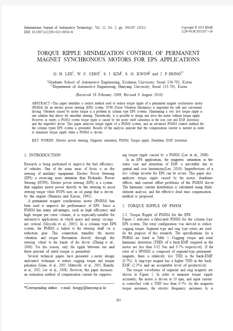
Figure 1 indicates a fabricated PMSM for the column type EPS system. The rotor configuration was skewed to reduce cogging torque. Segment type and ring type rotors are used for the purpose of this research. The specifications for a PMSM are listed in Table 1. Cogging torque and total harmonic distortion (THD) of a back-EMF required in the motor are less than 0.02 Nm and 0.7% respectively. If the rotor of a SPMSM is composed of segment-type permanent magnets, there is relatively low THD in the back-EMF (0.7%). A ring-type magnet has a higher THD in the back-EMF (2.3%) and an acceptable level of productivity.The torque waveforms of segment and ring magnets are shown in Figure 2. In order to measure torque ripple accurately, the motor is driven at 10 rpm, and input current is controlled with a THD less than 0.5%. As the magnetic torque increases, the electric frequency increases by a
*Corresponding author . e-mail: hongjp@hanyang.ac.kr
292G. H. LEE et al.
multiple of
6. Thus, even if the torque ripple displays
positive characteristics in the low torque region, the torque
ripple generated at the rated torque can’t be neglected.
Where the back-EMF of ring type rotor is converted into
synchronously rotating, the conversion between the back-
EMF of a ring type rotor and a synchronous rotor is
indicated to be the 6th voltage ripple as shown in Figure 3
The 6th pulsating voltage of a back-EMF frequency
appears in the synchronously rotating frame d, q-axis (E de, E qe).
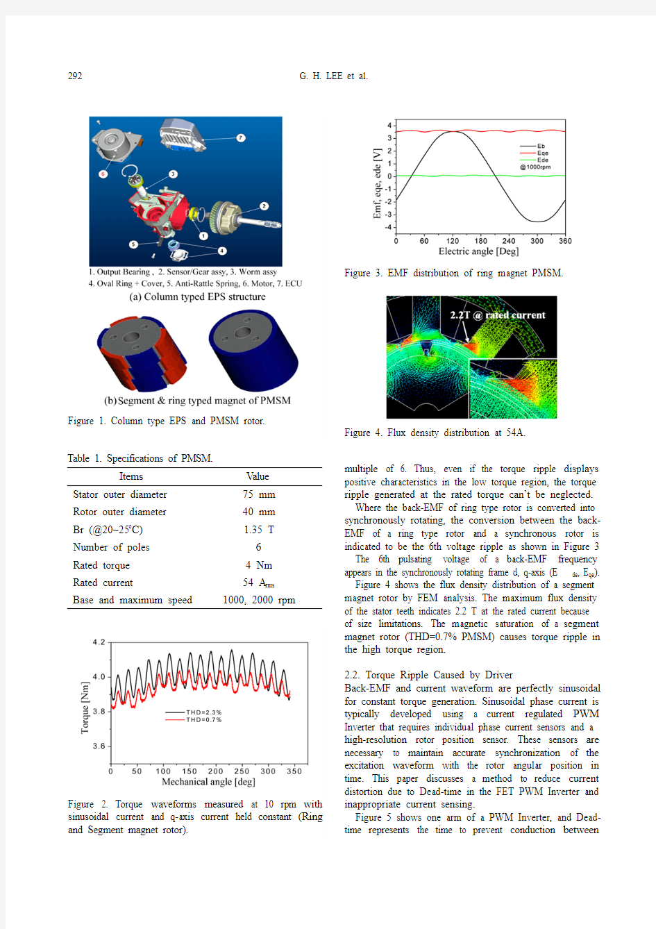
Figure 4 shows the flux density distribution of a segment
magnet rotor by FEM analysis. The maximum flux density
of the stator teeth indicates 2.2 T at the rated current because
of size limitations. The magnetic saturation of a segment
magnet rotor (THD=0.7% PMSM) causes torque ripple in
the high torque region.
2.2. Torque Ripple Caused by Driver
Back-EMF and current waveform are perfectly sinusoidal
for constant torque generation. Sinusoidal phase current is
typically developed using a current regulated PWM
Inverter that requires individual phase current sensors and a
high-resolution rotor position sensor. These sensors are
necessary to maintain accurate synchronization of the
excitation waveform with the rotor angular position in
time. This paper discusses a method to reduce current
distortion due to Dead-time in the FET PWM Inverter and
inappropriate current sensing.
Figure 5 shows one arm of a PWM Inverter, and Dead-
time represents the time to prevent conduction between Table 1. Specifications of PMSM.
Items Value
Stator outer diameter75 mm
Rotor outer diameter40 mm
Br (@20~25o C) 1.35 T
Number of poles6
Rated torque 4 Nm
Rated current54 A rms
Base and maximum speed1000, 2000 rpm
Figure 1. Column type EPS and PMSM rotor.
Figure 2. Torque waveforms measured at 10 rpm with
sinusoidal current and q-axis current held constant (Ring
and Segment magnet rotor).
Figure 3. EMF distribution of ring magnet PMSM.
Figure 4. Flux density distribution at 54A.
TORQUE RIPPLE MINIMIZATION CONTROL OF PERMANENT MAGNET 293
upper
and lower switches. The Field
Effect Transistor (FET) is widely used
for automotive applications to minimize the voltage drop of the switch. In the high voltage Inverter using the IGBT (Insulated Gate Bipolar Transistor), consideration of voltage drop in the switch is neglectable.
(1)
Consequently, Dead-time can be compensated by
generating a final voltage command by adding an ideal voltage command to the compensation voltage. This expression is shown in equation (1) and results from the current polarity during every switching period (Choi and Sul et al ., 1996). However, the voltage drop in the low voltage and high current Inverter should not be disregard
because the voltage drop in the switch is proportional to the phase current and voltage of the FET (Field Effect Transistor). Thus, voltage drops in the power FET (Field Effect Transistor) and diode should be compensated for more accurate current.
Since the field orientated Vector Control of a PMSM relies on current feedback, any inaccuracy in current sensing will have a direct impact on torque ripple performance. All current sensors inherently have offset and gain mismatch inaccuracies. In the current sensing circuit for the motor drive, the DC offset and gain mismatch have the most significant effects on the sensing error. The DC offset is caused by superposition of the DC voltage and the precise phase current. The superposition is caused by errors in the current sensor and amplifier. As a current sensor, a hall effect current sensor is commonly used. Magnetic hysteresis and asymmetry voltage sources are the main factors for the DC offset in the hall sensor. The mismatch of gain is mainly caused by the error of the amplifier in the current sensing circuit.
Generally, 2-phase currents are measured and used for 3-phase electric motors, and the unmeasured phase current is calculated considering the three phase symmetry. The DC offsets in the 2-phase current sensors and circuits are expressed as follows:(2)(3)
where, ?I a and ?I b are the DC offsets of the 2-phase sensor and I is the amplitude of the actual phase current. The c-phase current is used in the controller and is calculated in equation (4): and;
(4)
where, torque can be calculated using equation (5). From
the torque equations, peak to peak torque ripple is identical
if i as 0 V asComp V dead else V asComp V dead
–=,=>i a I θI a
?+sin =i b I θ2π3-----–??
??I b ?+sin =i c I a I b +I sin θ2π3-----+????I a ?I b
?––=–=Figure 5. Inverter one arm.
Figure 6. Measured voltage drop IGBT and FET.
Figure 7. Offset current according to the temperature (V oltage typed Hall effect current sensor, 150 A).
294G. H. LEE et al.
to frequency and can be expressed as equation (6).
(5)(6)
Equation (6) shows that the offset of current measure-ments cause the torque oscillation at the fundamental
frequency of motor current. Equation (6) also shows that current offset causes ripples with a synchronous frequency.The amplitude of torque ripples can be varied by offsetting the magnitude. Current offset caused by a current sensor is different according to current sensor characteristics, however,offset is almost constant regardless of current amplitude. In the A/D converter, offset is proportional or inversely proportional to the resolution and range of current used for converting. For example, if 1% offset of rated current exists in one phase, then 1.15% of current ripple of rated current for torque ripple is produced. If the offset exist in two phases, then 2% of current and torque ripple are produced.
3. MINIMIZA TION OF TORQUE RIPPLE CAUSED BY PMSM ITSELF
3.1. Torque Ripple Caused by EMF Distortion
A simple approach to calculate the optimized current waveform for eliminating ripple torque comes from recognizing that the instantaneous torque contributed by each machine phase is proportional to the product of back-EMF and phase current. As a result, the optimized current can be derived as being proportional to the reciprocal of the back-EMF under the appropriate conditions. This approach makes it possible to avoid the need for performing any harmonic analyses of the flux or back-EMF waveform. An electric power equation for a synchronously rotating frame is calculated using equation (7). Back-EMF , e we , e dge , has AC components. AC current injection into rotational frame currents i qe and i de is needed to cancel torque ripple.
(7)(8)
where, P, e qe , e de, i qe , i de, are power, synchronously rotating
frame q, d-axis back-EMF, and q, d-axis current,respectively. Variables e qeDC , e qeAC , i qeDC , and i qeAC are DC and AC components of e qe, DC and AC components of i qe
respectively. If the torque ripple of element e
qeAC i qeDC could be
eliminated by e qeDC i qeAC , e qeAC i qeAC +e deAC i deDC +e qeAC i deAC ,then the term would remain as a torque ripple term. Where harmonic THD is less than 3% in the back-EMF, the e qeAC i qeAC +e deAC i deDC +e qeAC i deAC term is far smaller than e qeAC i qeDC and it can be ignored. AC current i qeAC , is obtained using equation (8).
Since the back-EMF is proportional to speed, SPMSM can be operated with minimal torque ripple. Results of the proposed compensation method are shown in Figure 8.
T 1ωm ------e i i i
?I a b c
,,∑=EI ωm ------32--I a θsin θ2π3-----+????sin –????I b θ2π3-----–????θ2π3-----+????sin –sin ?????+?+??????=EI ωm ------=32--3I a θ2π3-----–????cos ?I b θcos –?+??????T ripple EI ωm ------23------I a θ2π3-----–??
??cos ?I b θcos –?=P 32--e qe i qe e de i de +()j 3
2
--e qe i de e de i qe +()
+=i qeAC e qeAC i qeDC e deAC i deDC
+e qeDC
---------------------------------------------=Figure 8. Simulation results of compensating EMF distortion.Figure 9. Compensation strategy to cancel torque ripple caused by EMF distortion.
TORQUE RIPPLE MINIMIZATION CONTROL OF PERMANENT MAGNET295
Figure 10 shows that torque ripple decreases.
3.2. Torque Ripple Caused by Magnetic Saturation
In this paper, FEA simulation is used to analyze the characteristics of PMSM and obtain the waveform of injection current to cancel torque pulsation. Nonlinear analysis considers the magnetic saturation of the stator core. As shown in Figures 11 and 12, the torque characteristics of PMSM are obtained by the FEA, and the analysis result is compared to the experimental result. The result at the rated current is similar to the experimental result. In the test, the PMSM is rotated at a low speed in order to drive the motor with a sinusoidal current. A nonlinear iteration method (current source analysis) is employed to obtain a q-axis current distribution that minimizes torque ripple according to the electric angle θe. The FEA is iterated at the each rotor position with varying I qeAC to search the flat torque waveform.
From this method, the compensation current which can minimize torque fluctuation, is calculated according to the current angle and is expressed in Figure 12. At the rated torque, a 2.5-A peak current is added to the q-axis current.
When
the d-axis current is forced to zero, the compensation current can be expressed as harmonic functions as shown in Figure 13.
The harmonics of the compensation current consist of 6th, 12th, 18th and 24th harmonic component. Therefore, if the 18th and 24th harmonic components are neglected, the current can be simplified as the function of i qeDC:
(9)
i qeAC0.0620.00028i qeDC2
+6θe
()
cos
?
=
0.0710.0056i qeDC
+
()12θe
()
cos
?
+
Figure 10. Test result with proposed strategy.
Figure 11. Torque waveform by FEA analysis with constant current.Figure 12. Torque waveform comparison of analysis and test result.
Figure 13. Harmonic components in the compensation current.
Figure 14. Current and injected current (Electric angle [5 rad/div], Injected Current [1 A/div], Phase Current [50A/ div], [200 msec/div].
296G. H. LEE et al.
(10)
Equation (9) is added to the q-axis current command to effectively minimize a torque ripple. Figure 14 shows test results for the phase and injected current.
Test results indicate that the 6 times torque harmonic of electric frequency is decreased to 30%. By injecting only 2% of the rated current, the torque ripple caused by the partial saturation could be effectively suppressed (Lee,2010).
4. MINIMIZA TION OF TORQUE RIPPLE CAUSED BY LOW VOLTAGE DRIVER
4.1. Compensation of Dead time Effect
To compensate for Dead-time effect in the low voltage AC driver, the voltage drop of FET and diode must be considered as described in Figure 7. This compensation voltage (V comp (i a )) is added to a final reference PWM voltage command and is shown in equation (10). Ideal voltage and real voltage of Low V oltage FET PWM Inverter and real compensation voltage are shown in Figure 15, 16 respectly.
(10)
where, V dipde (i a )=K diode i as +V diode _offset , V fet =i as R ds , t Di , t on , t off ,
T on
, and T s are Dead-time, turn on time, turn off time, PWM
on time and sampling time respectively.
V comp , V Diode , V fet and V dc are compensation voltage, FET voltage drop, diode voltage drop and DC link voltage respectively.
The following process is typically used as a solution for DC offset for current sensing. First, current is measured multiple times and average is calculated. Next, the averaged current is considered as an offset current and stored. Then the offset current is subtracted from the measured current during Inverter switching. i qe i qeDC i qeAC +=V comp i a ()t Di t on t off –+()V de V fet i a ()T on t on –t off +()T s
------------------------------?+?= V diode i a ()T off t off –()T s
---------------------?+Figure 15. Ideal voltage and real voltage of Low V oltage FET PWM Inverter (ias>0).
Figure 16. Compensation V oltage and Current Current [50A/div], V oltage [0.5/div], [20 msec/div].
Figure 17. Test result of proposed method.
Table 2. Experimental equipment.
Items
Value Switching frequency
20 kHz DSP TMX320F28335Power switch
FET-GWM 220-004Torque transducer HBM-T34FN
DC link voltage
12 V
TORQUE RIPPLE MINIMIZATION CONTROL OF PERMANENT MAGNET297
As shown in Figure 7, offset current varies with the temperature of the current sensor and the current sensing circuit. Therefore, an intermittent measurement of the offset current is required. The offset current should be measured when the Inverter is not operating.
Table 2 shows the experimental equipment used. The most recent digital signal processor from Texas Instruments, TMX320F28335, is employed to drive the motor. A switch-ing frequency of 20kHz is used to minimize high frequency current ripple.
The dynamometer system used to obtain torque ripple consists of a torque sensor, couplings, a load machine, a controller, a reduction gear and a data acquisition system. The torque sensor used is model "T34FN" and manufactured by HBM in Switzerland.The driver used is model "MP-55" at a maximum capacity of 10Nm. The load machine is a servo motor a with reduction gear for experiments in very low speeds. Test result of proposed method is shown Figure 17.
5. CONCLUSION
This paper presents an algorithm to reduce torque ripple, and the results were verified through experiments. Calculations of the effective harmonic currents for torque ripple reduction using FEM was described, and an improv-ed Dead-time compensation method for EPS systems was suggested. Experiments were performed with 12V, 100A PWM Inverter using DSP controller and SPMSM to confirm the suggested algorithm. REFERENCES
Bianchi, N., Pre, M. D. and Bolognani, S. (2006). Design of a fault-tolerant IPM motor for electric power steering.
IEEE Trans. Veh. Tech., 55, 4.
Choi, J.-W. and Sul, S.-K. (1996). Inverter output voltage synthesis using novel dead time compensation. IEEE Trans. Power Electronics 11, 2, 221?227.
Islam, M. S., Mir, S. and Sebastian, T. (2005). Design considerations of sinusoidally excited permanent-magnet machines for low-torque-ripple applications. IEEE Trans. Ind. Applicat.41, 4,955?962.
Lee, G. H. (2010). Active cancellation of PMSM torque ripple caused by magnetic saturation for EPS applications. JPE 10, 6, 176?180.
Lee, G. H., Kim, S. I. and Hong, J. P. (2008). Torque ripple reduction of interior permanent magnet synchronous motor using harmonic injected current. IEEE Trans. Magn. 44, 6, 1582?1585.
Mattavelli, P., Tubiana, L. and Zigliotto, M. (2005). Torque-ripple reduction in PM synchronous motor drives using repetitive current control. IEEE Trans. Power Electron. 20, 6,1423?1431.
Miyoshi, T., Shimizu, Y., Yoneda, A. and Tsujioka, T. (2005). Study on reducing the vibration of the 8 poles and 9 slots DC brushless motor for EPS. IEEJ, RM-05-128.
Shimizu, Y. and Kawai, T. (1991). Development of electric power steering. SAE Paper No.1991-0014
Zhang, X., Zhang, X., Shi, G. and Yi, L. (2008). Steering feel study on the performance of EPS. IEEE Vehicle Power and Propulsion Conf. (VPPC), September 3-5, 2008, Harbin, China.
齿槽转矩脉动 齿槽转矩是由转子的永磁体磁场同定子铁心的齿槽相互作用,在圆周方向产生的转矩。此转矩与定子的电流无关,它总是试图将转子定位在某些位置。在变速驱动中,当转矩频率与定子或转子的机械共振频率一致时,齿槽转矩产生的振动和噪声将被放大。齿槽转矩的存在同样影响了电机在速度控制系统中的低速性能,和位置控制系统中的高精度定位。解决齿槽转矩脉动问题的方法主要集中在电机本体的优化设计 上。 (1)斜槽法定子斜槽或转子斜极是抑制齿槽转矩脉动最有效且应用广泛的方法之一,该方法主要用于定子槽数较多且轴向较长的电机。实践表明,采用斜槽角度为10°时,齿槽转矩的基波转矩幅值相当于直槽时的90%,3次谐波幅值相当于直槽时的30%,5次谐波幅值相当于直槽时的19%。值得注意的是,为产生恒定的电磁转矩,反电动势波形必须是平顶宽度大于120°的理想梯形波,而斜槽或斜极引起的绕组反电动势的正弦化将会增大电磁转矩纹波。因此,选择合适的斜槽角度是有效抑制齿槽转矩脉动的关键。 (2)分数槽法该方法可以提高齿槽转矩基波的频率,使齿槽转矩脉动量明显减少。但是,采用了分数槽后,各极下绕组分布不对称,从而使电机的有效转矩分量部分被抵消,电机的平均转矩也会因此而相应减 小。 (3)磁性槽楔法采用磁性槽楔法就是在电机的定子槽口上涂压一层磁性槽泥,固化后形成具有一定导磁性能的槽楔。磁性槽楔减少了定子槽开口的影响,使定子与转子间的气隙磁导分布更加均匀,从而减少由于齿槽效应而引起的转矩脉动。由于磁性槽楔材料的导磁性能不是很好,因而对于转矩脉动的削弱程度有限。 (4)闭口槽法闭口槽即定子槽不开口,槽口材料与齿部材料相同。因槽口的导磁性能较好,所以闭口槽比磁性槽楔能更有效地消除转矩脉动。但采用闭口槽,给绕组嵌线带来极大不便,同时也会'大大增加槽漏抗,增大电路的时间常数,从而影响电机控制系统的动态特性。 (5)无齿槽绕组为了消除齿槽转矩脉动,可采用无槽绕组的永磁无刷直流电机,这种结构的电机定子可使用非导磁铁心的无齿槽空心杯定子结构(见图),能够彻底消除了齿槽转矩脉动的影响;但绕组电感显著减小,一般只有几μH到几十μH,因此定子电流中的PWM分量非常明显。
无刷直流电机转矩脉动抑制方法综述 周杰,侯燕 (河南工业大学电气工程学院,450007) 摘要:为扩大无刷直流电机在精度较高的伺服系统中的应用,必须尽量减小其转矩脉动。详细论述了无刷直流电机各种有效的转矩脉动抑制方法,并进行分类归纳。 关键词:无刷直流电机;转矩脉动;综述 中图分类号:TM33 文献标识码:B 文章编号:1004-0420(2007)06-0005-04 The review on torque ripple minimization of brushless DC motors ZHOU Jie,HOU Yan (College of Electrical Engineering,Henan University of Technology,450007) Abstract:To enlarge the application of brushless DC motor in higher accurateness servos,the torque ripple of brushless DC motor must be minimized. Aiming at the torque ripple attenuation of brushless DC motor,many efficient methods were discussed and classified in detail. Key words:brushless DC motor; torque ripple; review 0 引言 近年来,无刷直流电机(BLDCM)以其体积小、结构简单、功率密度高、输出转矩大、动态性能好等特点而得到了广泛应用[1],尤其是在机器人、精密电子仪器与设备等对电机性能、控制精度要求较高的场合和领域,其应用和研究更是受到普遍重视。目前,无刷直流电机最突出的问题就是具有转矩脉动,转矩脉动会直接降低电力传动系统控制特性和驱动
International Journal of Automotive Technology , Vol. 12, No. 2, pp. 291?297 (2011)DOI 10.1007/s12239?011?0034?8 Copyright ?2011KSAE 1229?9138/2011/057?16 291 TORQUE RIPPLE MINIMIZA TION CONTROL OF PERMANENT MAGNET SYNCHRONOUS MOTORS FOR EPS APPLICA TIONS G . H. LEE 1), W. C. CHOI 1), S. I. KIM 2), S. O. KWON 2) and J. P . HONG 2)* 1) Graduate School of Automotive Engineering, Kookmin University, Seoul 136-702, Korea 2) Department of Automotive Engineering, Hanyang University, Seoul 133-791, Korea (Received 18 February 2009; Revised 9 August 2010) ABSTRACT ?This paper identifies a control method used to reduce torque ripple of a permanent magnet synchronous motor (PMSM) for an electric power steering (EPS) system. NVH (Noise Vibration Harshness) is important for safe and convenient driving. Vibration caused by motor torque is a problem in column type EPS systems. Maintaining a very low torque ripple is one solution that allows for smoother steering. Theoretically, it is possible to design and drive the motor without torque ripple.However, in reality, a PMSM system torque ripple is caused by the motor itself (saturation in the iron core and EMF distortion)and the imperfect driver. This paper analyzes torque ripple of a PMSM system, and an advanced PMSM control method for the column typed EPS system is presented. Results of the analysis indicate that the compensation current is needed in order to minimize torque ripple when a PMSM is driven. KEY WORDS :Electric power steering, Magnetic saturation, PMSM, Torque ripple, Deadtime, EMF distortion 1. INTRODUCTION Research is being performed to improve the fuel efficiency of vehicles. One of the main areas of focus is on the steering of auxiliary equipment. Electric Power Steering (EPS) is receiving more attention than Hydraulic Power Steering (HYPS). Electric power steering (EPS) is a system that supplies motor power directly to the steering to assist steering torque while HYPS uses an oil pump that is driven by the engine (Shimizu and Kawai, 1991). A permanent magnet synchronous motor (PMSM) has been used to improve the performance of EPS. Since a PMSM has many advantages, such as high efficiency and high torque per rotor volume, it is especially suitable for automotive applications in which space and energy savings are critical (Miyoshi et al ., 2005). In a column type EPS system, the PMSM is linked to the steering shaft via a reduction gear. This connection transfers the motor vibration and torque fluctuation directly through the steering wheel to the hands of the driver (Zhang et al .,2008). For this reason, only the ripple between one and three percent of rated torque is permitted. Several technical papers have presented a motor design andcontrol technique to reduce cogging torque and torque pulsation (Islam et al ., 2005; Mattavelli et al ., 2005; Bianchi et al ., 2002; Lee et al ., 2008). However, this paper discusses an estimation method of compensation current for suppress-ing torque ripple caused by a PMSM (Lee et al ., 2008).In an EPS application, the magnetic saturation in the stator core and distortion of EMF is inevitable due to spatial and cost limitations(Lee, 2010). Imperfections of a low voltage inverter for EPS can be severe. This paper also analyzes torque ripple caused by the motor, deadtime effects, and current offset problems of the PMSM driver.The harmonic current distribution is calculated using finite element analysis, and the effective dead time compensation method is proposed. 2. TORQUE RIPPLE OF PMSM 2.1. Torque Ripple of PMSM for the EPS Figure 1 indicates a fabricated PMSM for the column type EPS system. The rotor configuration was skewed to reduce cogging torque. Segment type and ring type rotors are used for the purpose of this research. The specifications for a PMSM are listed in Table 1. Cogging torque and total harmonic distortion (THD) of a back-EMF required in the motor are less than 0.02 Nm and 0.7% respectively. If the rotor of a SPMSM is composed of segment-type permanent magnets, there is relatively low THD in the back-EMF (0.7%). A ring-type magnet has a higher THD in the back-EMF (2.3%) and an acceptable level of productivity.The torque waveforms of segment and ring magnets are shown in Figure 2. In order to measure torque ripple accurately, the motor is driven at 10 rpm, and input current is controlled with a THD less than 0.5%. As the magnetic torque increases, the electric frequency increases by a *Corresponding author . e-mail: hongjp@hanyang.ac.kr
方波无刷直流电机转矩脉动分析 作 者:中国中铁电气化局集团第二工程有限公司 李 庆 [专家点评] 引言 永磁方波无刷直流电动机具有体积小、重量轻、出力大、控制简单和调速方便等优点,被广泛应用于军事、工业和家电等各行业。但是,方波无刷直流电机转矩脉动大,限制了它在一些场合的应用。转矩脉动主要是由于电磁因素引起的,本文分析了无刷直流电动机转矩脉动的成因,并从系统的观点提出改善转矩脉动的措施。 方波无刷直流电机转矩脉动成因[2] 永磁无刷直流电动机的气隙磁场为方波,相应的逆变装置采用二二导通模式,以保证定子电流波形与气隙磁场波形一致,这样电机转矩脉动最小,几乎为零。但是现实中做到定子电流波形与气隙磁场波形完全一致是不可能的,同时由于电机本身存在定子绕组的换流问题,这就带来了转矩的脉动。从转矩公式 (1) 式中:t e为转矩;为相反电;为相电流;ω角速度;从式中可以看出,转矩脉动主要与定子电流和气隙磁场有关。 定子电流对转矩脉动的影响 控制逆变装置目的就是调整电流,使之尽量接近理想的方波波形,但是由于定子绕组存在电感,使得定子中的电流上升和下降都有个过程,使得定子电流达不到理想方波波形,导致了转矩的脉动。同时由于斩波频率的限制,非换相期间电流的脉动也带来的精度允许范围之内的转矩脉动。 气隙磁场对转矩脉动的影响 电机气隙磁场在设计时是梯形波磁场,但是由于机械加工制造等方面的影响,使得气隙磁场达不到理想的梯形波形,同时由于定子齿槽的存在使得气隙磁场有脉动[1];当电机带负载运行时,定子磁场与转子磁场相互作用,有电枢反应,使得气隙磁场产生畸变,偏离理想梯形波,这也带来了转矩的脉动。 抑制转矩脉动的措施 为了抑制转矩脉动主要从三方面来采取措施: (1)从主回路角度,尽量采用高频器件,提高谐波次数,减少谐波转矩脉动; (2)从控制的角度,采用最佳的逆变器控制模式,尽量增加有效电磁转矩,采用合适的控制方法抑制换流带来的电流脉动导致的转矩脉动;