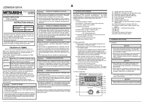
JZ990D41201AMITSUBISHI POWER AMPLIFIRECautions on Safety(Make sure to read this paragraph before using the unit.)Make sure to thoroughly read this instruction manual, techni-cal data, etc. before using the unit, and pay attention toassure safety while using the unit.In this manual, cautions on safety are classified into "DAN-GER" and "CAUTION".°important and it may lead to a serious result depending onthe situation. Make sure to observe every item.The unit is manufactured under severe quality control sys-tem. When applying the unit to a facility where a failure of theunit may lead to a serious accident or loss, however, system-atically install the backup or fail-safe function.Carefully store this instruction manual so that it can bereferred to at any time if necessary, and see to it that the enddisassembly, modification, etc. performed by a third party otherthan MITSUBISHI or a company specified by MITSUBISHI.Accordingly, ask a service network specified by MITSUBISHI forrepairs and disassemblies.The above cautions on safety and the specifications described inthe instruction manual and technical data are subject to changewithout prior notice.1.Functions and FeaturesThe power amplifire LD-40PSU is designed only for powderclutches/brakes and hysteresis clutches/brakes. This poweramplifire operates in a wide power range of 85 to 264 VAC, and isequipped with built-in control outputs of 24 VDC/3.8 A.1)Features(1) Switching regulator method(2) Operates in a wide power range of 85 to 264 VAC.(3) Constant voltage control method(4) External control signal(RC: Remote control ON/OFF input)(5) Digital display (4-digit, 7-segment LED)(6) Input for external variable resistor(SP: Analog signal input)(7) Protection against load short-circuit and short-circuitwarning indication (OC-LED)(8) Output two-step switching function(9) Power factor of 80% or more2)Major applications(1) Manual power supply unit controlled through the vari-able resistor on the panel surface.(2) Manual power supply unit controlled through an exter-nal variable resistor.• The output can be adjusted using an external variableresistor when the variable resistor provided on thepanel surface is made invalid and a variable resistor of500 to 2kΩ (1/2 W or more) is connected to the outputterminal (5V) and input terminal (SP-SN).(3) Power amplifier using an external voltage signal• The output can be adjusted using an external voltagesignal when the variable resistor provided on thepanel surface is made invalid and the voltage of 0 to 5V is input to the input terminal (SP-SN).(4) Output two-step switching function• The output in the output OFF condition can beadjusted within the range from 0 to 100%. The outputcan be switched in two steps using a knob or an exter-nal voltage signal.3)Panel configuration[1] Voltage adjusting variable resistor[2] [MODE] key--Changes over the adjustment mode.[3] Adjustment mode indicator LED (green)[4] Overcurrent detection indicator LED (red)[5] Power ON indicator LED (green)[6] 7-segment display[7] Voltage indicator LED (red)[8] Output voltage (V)/output percentage (%) displayselector key[9] Output percentage (%) indicator LED (red)[10] External variable resistor validity indicator LED(green)[11] [SET] key-----Determines data setting.[12] [ S ] key[13] [ T ] key[14] Output ON indicator LED (green)[15] Output ON/OFF selector switch2.Installation and Wiring1)Installationface or panel surface.POWER AMPLIFIRETYPE LD-40PSUINSTRUCTION MANUALThoroughly read this instruction manual, and then usethe unit correctly. Especially, make sure to read "Cau-tions on Safety" before using the unit.Carefully store this instruction manual, and see to it thatthe end user receives it.This printed matter is issued in March 2005. The specifi-cations are subject to change without prior notice.Manual number JZ990D41201Sub number ADate of preparation Nov. 2005ZJ-4065Aa)Installation on floor surfacemake valid the variable resistor on the panel surface, and make invalid the input signal for control.• valid.4)Changeover of output display• The output voltage (V) or output percentage (%) is dis-played on the 7-segment display [6].• Press the display selector key [8] to alternately select the output voltage (V) and output percentage (%).5)Output ON/OFF functiona)Use the output ON/OFF switch [15] on the panel sur-face or [RC] signal to set the output to ON or OFF.• When the [RC] signal is set to ON, the output is generated without regard to the setting of the out-put ON/OFF switch [15] on the panel surface.• When the [RC] signal is set to OFF , the output ON/OFF switch [15] on the panel surface becomes valid. Every time the output ON/OFF switch is pressed, the output is set to "ON → OFF → ON " alternately.• Stop timer setting range :7)[OC] is displayed on the 7-segment display [6], and [OC] and the overcurrent detection indicator LED [4] flicker alternately.• When the overcurrent detection indicator LED [4] lights, check the external wiring and release the short-circuit status.• After releasing the short-circuit status, turn off the power, wait for 30 seconds or more, and then turn on the power to recover the unit to the normal status.4.Adjustment1)Screen changeover method2)Changeover to the adjustment mode• While the power is ON, press and hold the [MODE] key [2] for 1 second or more to select the adjustment mode. At this time, the adjustment mode indicator LED [3] lights.• The output voltage value just before changeover to the adjustment mode is maintained.If the voltage adjusting variable resistor [1] or an external variable resistor is turned after the adjustment mode is selected, the output voltage changes accordingly. However, the value after change is not displayed on the 7-segment display [6].When the adjustment mode is finished, the output voltage value or output percentage value after change is displayed.• For finishing the adjustment mode, press and hold the [MODE] key [2] again for 1 second or more.• Press the display selector key in the adjustment mode to display the present output.(Note) If any key is not pressed for 10 seconds or more after the adjustment mode is selected, the normal mode is auto-matically selected.3)Functions of the keys on the panel surface -----------In the adjustment mode, each key has the following function.• [MODE] key [2]Press and hold this key for 1 second or more in the normal mode to select the adjustment mode. When the adjustment mode is selected, the adjustment mode indicator LED [3] lights.For selecting the normal mode after setting of the parameters is completed, press and hold this key for 1 second or more.• [S ] key [12]Use this key for selecting either of the adjustment items 1 to 3 in the adjustment mode. Every time this key is pressed, the adjustment item No. is changed in the order "3 → 2 → 1".After selecting an adjustment item, press this key to increase the set value. Press and hold this key for 2 seconds or more to automatically increase the set value.• [T ] key [13]Use this key for selecting either of the adjustment items 1 to 3 in the adjustment mode. Every time this key is pressed, the adjustment item No. is changed in the order "1 → 2 → 3".After selecting an adjustment item, press this key to decrease the set value. Press and hold this key for 2 seconds or more to automatically decrease the set value. • [SET] key [11]After selecting an adjustment item, press this key to determine the selected adjustment item and enable setting of a numeric value.After setting a numeric value, press this key to store the set value and return to the adjustment item selection status.•Press this key once in the adjustment mode to change over the display contents on the 7-segment display between the output voltage (V) monitoring and the output voltage adjustment (%) monitoring.If any key is not pressed for 5 seconds in the monitoring display status, the display contents automatically return to the status just before the display selector key is pressed. At this time, if the display selector key is in the numeric value set-ting status, the numeric value being set is canceled.If the display selector key is pressed again in the monitoring display status, the output voltage (V) monitoring and output voltage adjustment (%) monitoring are changed over alternately every time the display selector key is pressed.• [OUTPUT] key [14]This key turns on and off the output voltage between the PP and PN terminals.Every time this key is pressed, the output is set to "ON → OFF → ON" alternately.The RC signal input has higher priority. Even if this key is set to "output OFF", the output is ON while the RC signal input is ON.4)Adjustment method-----------Press and hold the [MODE] key [2] for 1 second or more to select the adjustment mode, and thenset the value of each item described below.a)OFS (output OFF ) setting• Set the voltage output while the output is set to OFF (while the OUTPUT LED [14] is extinguished).• When the output is set to OFF using the procedure described in 3-3), the voltage set here is output.• This function can be used for setting the weak exciting voltage of the powder clutch while the output is OFF .• Setting range-------0 to 100% ---------Initial value = 0% (100% = Maximum output voltage, approx. 26 V)• Setting method [1] Select "1. OFS" using the [S ] key [12] or [T ] key [13].[2] Press the [SET] key [11] to determine the item No. 1.[3] Set a numeric value using the [ S ] key [12] or [T ] key [13].[4] Press the [SET] key [11] to determine the numeric value.b)SPO (stop output) setting• Set the voltage output while the stop timer is operating.• Setting range-------0 to 100%----------• Setting method [1] Select "2. SPO" using the [S ] key [12] or [T ] key [13].[2] Press the [SET] key [11] to determine the item No. 2.[3] Set a numeric value using the [S ] key [12] or [T ] key [13].[4] Press the [SET] key [11] to determine the numeric value.c)SPT (stop timer) setting • Set the stop timer.• • Setting method[1] Select "3. SPT" using the [S ] key [12] or [T ] key [13].[2] Press the [SET] key [11] to determine the item No. 3.[3] Set a numeric value using the [S ] key [12] or [T ] key [13].[4] Press the [SET] key [11] to determine the numeric value.5)Set item list5.Setting Initialization• If the [S ] key [12] and [T ] key [13] are pressed at the same time when the power is turned on, "InIT" is displayed for 10 sec-onds on the 7-segment display [6]. The version is not displayed.• Press the [SET] key [11] while "InIT" is displayed to initialize various settings and return the unit to the status at the time of shipment.• At this time, the "V" unit indicator LED [7] and "%" unit indicator LED [9] are extinguished, and only the power ON indicator LED [5] is lit.• When initialization is completed, the version flickers for 5 seconds, the normal mode, voltage monitoring display and output OFF status are selected, and then the power ON indicator LED [5] and voltage indicator LED [7] light.• If the [SET] key [11] is not pressed, "InIT" flickers for 10 seconds, and then the normal mode is selected in the same way as Set item Unit Setting rangeInitial valueMinimum valueMaximum valueOutput OFF setting%01000Stop output %01000Stop timersec0.030.00.06.Inspection and Maintenanceing devices and direct sunlight• Whether dusts and conductive dusts have not entered the panel• Whether abnormality in the wiring, loose terminals and other abnormalities are not present7.Specifications1)I/O specifications9.External wiring diagram and terminal arrangementJZ990D41201AMITSUBISHI POWER AMPLIFIRECautions on Safety(Make sure to read this paragraph before using the unit.)Make sure to thoroughly read this instruction manual, techni-cal data, etc. before using the unit, and pay attention toassure safety while using the unit.In this manual, cautions on safety are classified into "DAN-GER" and "CAUTION".°important and it may lead to a serious result depending onthe situation. Make sure to observe every item.The unit is manufactured under severe quality control sys-tem. When applying the unit to a facility where a failure of theunit may lead to a serious accident or loss, however, system-atically install the backup or fail-safe function.Carefully store this instruction manual so that it can bereferred to at any time if necessary, and see to it that the enddisassembly, modification, etc. performed by a third party otherthan MITSUBISHI or a company specified by MITSUBISHI.Accordingly, ask a service network specified by MITSUBISHI forrepairs and disassemblies.The above cautions on safety and the specifications described inthe instruction manual and technical data are subject to changewithout prior notice.1.Functions and FeaturesThe power amplifire LD-40PSU is designed only for powderclutches/brakes and hysteresis clutches/brakes. This poweramplifire operates in a wide power range of 85 to 264 VAC, and isequipped with built-in control outputs of 24 VDC/3.8 A.1)Features(1) Switching regulator method(2) Operates in a wide power range of 85 to 264 VAC.(3) Constant voltage control method(4) External control signal(RC: Remote control ON/OFF input)(5) Digital display (4-digit, 7-segment LED)(6) Input for external variable resistor(SP: Analog signal input)(7) Protection against load short-circuit and short-circuitwarning indication (OC-LED)(8) Output two-step switching function(9) Power factor of 80% or more2)Major applications(1) Manual power supply unit controlled through the vari-able resistor on the panel surface.(2) Manual power supply unit controlled through an exter-nal variable resistor.• The output can be adjusted using an external variableresistor when the variable resistor provided on thepanel surface is made invalid and a variable resistor of500 to 2kΩ (1/2 W or more) is connected to the outputterminal (5V) and input terminal (SP-SN).(3) Power amplifier using an external voltage signal• The output can be adjusted using an external voltagesignal when the variable resistor provided on thepanel surface is made invalid and the voltage of 0 to 5V is input to the input terminal (SP-SN).(4) Output two-step switching function• The output in the output OFF condition can beadjusted within the range from 0 to 100%. The outputcan be switched in two steps using a knob or an exter-nal voltage signal.3)Panel configuration[1] Voltage adjusting variable resistor[2] [MODE] key--Changes over the adjustment mode.[3] Adjustment mode indicator LED (green)[4] Overcurrent detection indicator LED (red)[5] Power ON indicator LED (green)[6] 7-segment display[7] Voltage indicator LED (red)[8] Output voltage (V)/output percentage (%) displayselector key[9] Output percentage (%) indicator LED (red)[10] External variable resistor validity indicator LED(green)[11] [SET] key-----Determines data setting.[12] [ S ] key[13] [ T ] key[14] Output ON indicator LED (green)[15] Output ON/OFF selector switch2.Installation and Wiring1)Installationface or panel surface.a)Installation on floor surfaceb)Installation on panel surfaceScrew hole dimensionPanel cut dimension formounting on panel surface2)Wiringa)Wiring method and cautions• The terminal block for external connection is providedin the lower portion of the rear face.(grounding resistance:100 Ω or less) using a shielding wire on the signalreceiving side for the analog signal input and outputlines and spool pulse input line.• Never put the input and output lines together with otherpower lines into a same duct. Never bundle the inputand output lines together with other power lines.• Never tighten two wires together on the terminal block.Otherwise, the terminal block may fail.(When tightening two wires together, attach two wiresto one terminal, and attach one wire to the terminalblock.)Generally, set the wiring length to 10 m or less toassure safety against noise.<Caution>Note that the knob may be damaged if load is appliedon the panel surface facing downward during wiring tothe terminal block.This manual power supply unit is electronic equip-ment equipped with a built-in micro computer (CPU).If conductive substances enter the main body or if theCPU becomes out of order due to abnormal noiseentered from the outside, the output from the unit isfixed. When the cause is noise, remove the noisesource, turn off the power, and then turn on the powerto recover the unit to the normal status.b)Wiring of an external variable resistor• Wire an external knob using four-core shielding wiresas shown in the figure below.• Do not groundthe SG terminalground the SGterminal.c)Power switch• This unit is not equipped with the power ON/OFFswitch. It is recommended to connect a switch orbreaker outside the unit.3.Operations and Functions during Operation1)Version display• When the power is turned on, the version is displayed onthe 7-segment display for 2 seconds.2)Adjustment of the output voltagea)Adjustment using the variable resistor on the panel sur-face• The output voltage can be adjusted within the rangefrom "0" to the maximum value using the voltageadjusting variable resistor [1].(Maximum output voltage = 26 V)b)Adjustment using an external variable resistor• The output voltage can be adjusted using an externalvariable resistor described in 2-2)-b) by pressing andholding the [SET] key as described in 3-3) below.3)Changeover of output voltage adjustment between the vari-able resistor on the panel surface and the input signal forcontrol• In the output OFF status in the normal mode, press andhold the [SET] key [11] for 1 second or more to light the[REMOTE] indicator LED [10], make invalid the knob onthe panel surface, and make valid the input signal for con-trol (SP-SN).• Press and hold the [SET] key [11] again for 1 second ormore to extinguish the [REMOTE] indicator LED [10] ,make valid the variable resistor on the panel surface,and make invalid the input signal for control.•valid.4)Changeover of output display• The output voltage (V) or output percentage (%) is dis-played on the 7-segment display [6].• Press the display selector key [8] to alternately selectthe output voltage (V) and output percentage (%).5)Output ON/OFF functiona)Use the output ON/OFF switch [15] on the panel sur-face or [RC] signal to set the output to ON or OFF.• When the [RC] signal is set to ON, the output isgenerated without regard to the setting of the out-put ON/OFF switch [15] on the panel surface.• When the [RC] signal is set to OFF, the output ON/OFF switch [15] on the panel surface becomesvalid. Every time the output ON/OFF switch ispressed, the output is set to "ON → OFF → ON "alternately.• While the output is ON, the output indicator LED[14] is lit.b)In the output OFF condition, the output voltage set inthe "output OFF setting" in the adjustment mode isoutput.• Output OFF setting range :0 to 100%---------Initial value = 0%• While the output is OFF, “OFF” flickers on the 7-segment display [6].• While the output OFF setting is not set to "0", out-put OFF setting “1. OFS” flickers.6)Inertia compensation function• During the "stop timer" setting period after the [RC] sig-nal is set to OFF from ON, the output set in "stop out-put" is generated.• Stop timer setting range :0.0 to 9.9 s,10.0 to 30.0 s--Initial value = 0.0 s• Stop output setting range :0 to 100%----------------------Initial value = 0%7)Load short-circuit protection function• When the load between the PP and PN terminals isshort-circuited, the output is shut down. At this time,[OC] is displayed on the 7-segment display [6], and[OC] and the overcurrent detection indicator LED [4]flicker alternately.• When the overcurrent detection indicator LED [4] lights,check the external wiring and release the short-circuitstatus.• After releasing the short-circuit status, turn off thepower, wait for 30 seconds or more, and then turn onthe power to recover the unit to the normal status. POWER AMPLIFIRETYPE LD-40PSUINSTRUCTION MANUALThoroughly read this instruction manual, and then usethe unit correctly. Especially, make sure to read "Cau-tions on Safety" before using the unit.Carefully store this instruction manual, and see to it thatthe end user receives it.This printed matter is issued in March 2005. The specifi-cations are subject to change without prior notice.Manual number JZ990D41201Sub number ADate of preparation Nov. 2005ZJ-4065A4.Adjustment1)Screen changeover method2)Changeover to the adjustment mode• While the power is ON, press and hold the [MODE] key [2] for 1 second or more to select the adjustment mode. At this time, the adjustment mode indicator LED [3] lights.• The output voltage value just before changeover to the adjustment mode is maintained.If the voltage adjusting variable resistor [1] or an external variable resistor is turned after the adjustment mode is selected, the output voltage changes accordingly. However, the value after change is not displayed on the 7-segment display [6].When the adjustment mode is finished, the output voltage value or output percentage value after change is displayed.• For finishing the adjustment mode, press and hold the [MODE] key [2] again for 1 second or more.• Press the display selector key in the adjustment mode to display the present output.(Note) If any key is not pressed for 10 seconds or more after the adjustment mode is selected, the normal mode is auto-matically selected.3)Functions of the keys on the panel surface -----------In the adjustment mode, each key has the following function.• [MODE] key [2]Press and hold this key for 1 second or more in the normal mode to select the adjustment mode. When the adjustment mode is selected, the adjustment mode indicator LED [3] lights.For selecting the normal mode after setting of the parameters is completed, press and hold this key for 1 second or more.• [S ] key [12]Use this key for selecting either of the adjustment items 1 to 3 in the adjustment mode. Every time this key is pressed, the adjustment item No. is changed in the order "3 → 2 → 1".After selecting an adjustment item, press this key to increase the set value. Press and hold this key for 2 seconds or more to automatically increase the set value.• [T ] key [13]Use this key for selecting either of the adjustment items 1 to 3 in the adjustment mode. Every time this key is pressed, the adjustment item No. is changed in the order "1 → 2 → 3".After selecting an adjustment item, press this key to decrease the set value. Press and hold this key for 2 seconds or more to automatically decrease the set value. • [SET] key [11]After selecting an adjustment item, press this key to determine the selected adjustment item and enable setting of a numeric value.After setting a numeric value, press this key to store the set value and return to the adjustment item selection status.•Press this key once in the adjustment mode to change over the display contents on the 7-segment display between the output voltage (V) monitoring and the output voltage adjustment (%) monitoring.If any key is not pressed for 5 seconds in the monitoring display status, the display contents automatically return to the status just before the display selector key is pressed. At this time, if the display selector key is in the numeric value set-ting status, the numeric value being set is canceled.If the display selector key is pressed again in the monitoring display status, the output voltage (V) monitoring and output voltage adjustment (%) monitoring are changed over alternately every time the display selector key is pressed.• [OUTPUT] key [14]This key turns on and off the output voltage between the PP and PN terminals.Every time this key is pressed, the output is set to "ON → OFF → ON" alternately.The RC signal input has higher priority. Even if this key is set to "output OFF", the output is ON while the RC signal input is ON.4)Adjustment method-----------Press and hold the [MODE] key [2] for 1 second or more to select the adjustment mode, and thenset the value of each item described below.a)OFS (output OFF ) setting• Set the voltage output while the output is set to OFF (while the OUTPUT LED [14] is extinguished).• When the output is set to OFF using the procedure described in 3-3), the voltage set here is output.• This function can be used for setting the weak exciting voltage of the powder clutch while the output is OFF .• Setting range-------0 to 100% ---------Initial value = 0% (100% = Maximum output voltage, approx. 26 V)• Setting method [1] Select "1. OFS" using the [S ] key [12] or [T ] key [13].[2] Press the [SET] key [11] to determine the item No. 1.[3] Set a numeric value using the [ S ] key [12] or [T ] key [13].[4] Press the [SET] key [11] to determine the numeric value.b)SPO (stop output) setting• Set the voltage output while the stop timer is operating.• Setting range-------0 to 100%----------• Setting method [1] Select "2. SPO" using the [S ] key [12] or [T ] key [13].[2] Press the [SET] key [11] to determine the item No. 2.[3] Set a numeric value using the [S ] key [12] or [T ] key [13].[4] Press the [SET] key [11] to determine the numeric value.c)SPT (stop timer) setting • Set the stop timer.• • Setting method[1] Select "3. SPT" using the [S ] key [12] or [T ] key [13].[2] Press the [SET] key [11] to determine the item No. 3.[3] Set a numeric value using the [S ] key [12] or [T ] key [13].[4] Press the [SET] key [11] to determine the numeric value.5)Set item list5.Setting Initialization• If the [S ] key [12] and [T ] key [13] are pressed at the same time when the power is turned on, "InIT" is displayed for 10 sec-onds on the 7-segment display [6]. The version is not displayed.• Press the [SET] key [11] while "InIT" is displayed to initialize various settings and return the unit to the status at the time of shipment.• At this time, the "V" unit indicator LED [7] and "%" unit indicator LED [9] are extinguished, and only the power ON indicator LED [5] is lit.• When initialization is completed, the version flickers for 5 seconds, the normal mode, voltage monitoring display and output OFF status are selected, and then the power ON indicator LED [5] and voltage indicator LED [7] light.• If the [SET] key [11] is not pressed, "InIT" flickers for 10 seconds, and then the normal mode is selected in the same way as Set item Unit Setting rangeInitial valueMinimum valueMaximum valueOutput OFF setting%01000Stop output %01000Stop timersec0.030.00.06.Inspection and Maintenance1)Initial inspectiona)Before turning on the power, check whether the applied load is proper (24 VDC, 3.8 A or less).b)Incorrect connection of the power terminal, contact between the DC input/output wiring and the power wiring, short-circuit of the output wiring, etc. can cause serious damage in the equipment.c)Before turning on the power, check whether the power supply is connected correctly, whether the grounding terminal is connected correctly, and whether the input/output wiring is performed correctly.d)Check whether the commutation diode is not directly connected to the excit-ing coil of the clutch or brake connected to the control output terminal, and whether the PN and SN terminals are not short-circuited.e)Take care so that wire chips and lead wire chips do not enter from ventilation holes on the case top face and sides during wiring.f)To the power ON indicator LED[5], the power is supplied from the secondary circuit of the internal switching power supply.2)Maintenance inspectiona) Consumable parts which can reduce the life of the unit are not built in the unit. However, the standard replacement frequency of the aluminum electrolytic capacitor is 5 years. This frequency varies depending on the ambient work-ing temperature, output current, operating time, etc. Contact Mitsubishi Sys-tem Services if necessary.b) The life of the EEPROM for storing various setting data is 100,000 times of writing. The number of times of power ON/OFF is limited to 100,000 times or less.c) In the periodic inspection, check the following items:• Whether the temperature inside the panel is not normally high due to heat-ing devices and direct sunlight• Whether dusts and conductive dusts have not entered the panel• Whether abnormality in the wiring, loose terminals and other abnormalities are not present7.Specifications1)I/O specifications2)Environmental specificationsl8.Outside DimensionsAmbient temperature -5 ~ +55°cAmbient humidity 35 ~ 80% RH or less ( no condensation)Vibration resistance In accordance with JIS C0040. 10 to 55 Hz, 0.5mm (4. 9m / s 2 maximum),2 hours in each of three axis directionsImpact resistanceIn accordance with JIS C0041. 98m / s 2, 3 times in each of three axis directions.S upply noise resi s-tance By noise simulator with 1,000 Vp-p noise voltage, 1 µs noise width and 30 to 100 Hz .Withstand voltage1,500V AC, 1 minute• Between entire terminals as a whole (except grounding terminal) and ground terminal.• Between entire terminals as a whole (except grounding terminal) and metal fixture.Insulation resistance 5M Ω or more by 500V DC meggerBetween entire terminals as a whole and ground terminal.GroundingSolid grounding (100Ωor less)Operating atmosphereCorrosive gas, combustible gas, conductive dusts and many dusts shall not be present.9.External wiring diagram and terminal arrangementconnect the non-active line side to the [ N ] terminal.。