数控加工注塑模具板
许多机械工程师在他大学毕业后加入了需要计算机数学控制(数控)的加工和设计部门,可是没有多少毕业生现成的使用CNC 机械生产复杂的CNC部件。如果学生们对数控编程、夹具、数控机床进行更加熟悉,在设计阶段我们可以避免许多制造难度和节约成本。为了解决这个问题,CNC加工过程开发出来。这个设计需要学生为了兴趣去设计和制造注塑模具。这个设计是一个独特加工结构。在工业中为注塑模具而设计时,我们选择的注塑造型非常流行,许多有趣的设计所包含的内容被超越。这个工作展示了一个教授电脑辅助绘图,创新的结构化小团体,为了获得更好的部分生产设计,这个团体教授所需要的设计技工了。
问题
教你如何最好的学生设计的必要技能创建复杂的计算机数字控制(CNC)部分?
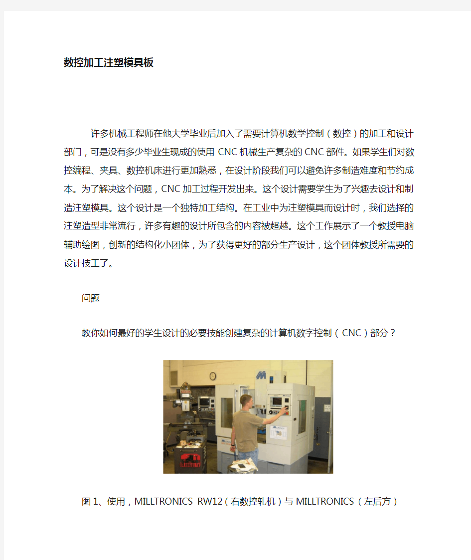
图1、使用,MILLTRONICS RW12(右数控轧机)与MILLTRONICS(左后方)
引言
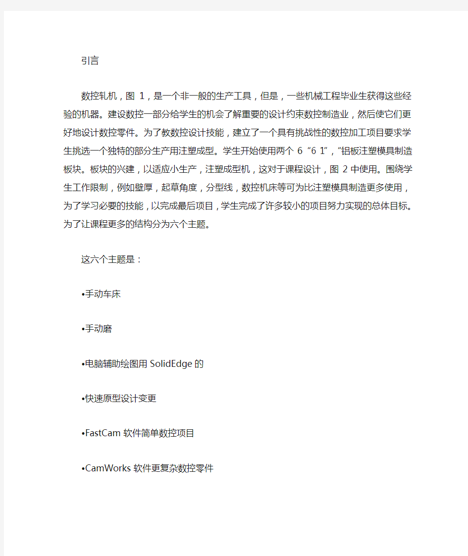
数控轧机,图1,是一个非一般的生产工具,但是,一些机械工程毕业生获得这些经验的机器。建设数控一部分给学生的机会了解重要的设计约束数控制造业,然后使它们更好地设计数控零件。为了教数控设计技能,建立了一个具有挑战性的数控加工项目要求学生挑选一个独特的部分生产用注塑成型。学生开始使用两个6“6 1”,“铝板注塑模具制造板块。板块的兴建,以适应小生产,注塑成型机,这对于课程设计,图2中使用。围绕学生工作限制,例如壁厚,起草角度,分型线,数控机床等可为比注塑模具制造更多使用,为了学习必要的技能,以完成最后项目,学生完成了许多较小的项目努力实现的总体目标。为了让课程更多的结构分为六个主题。
这六个主题是:
?手动车床
?手动磨
?电脑辅助绘图用SolidEdge的
?快速原型设计变更
?FastCam软件简单数控项目
?CamWorks软件更复杂数控零件
图2:注塑机
手动车床
为了让学生积极参与机械车间,学生完成一个小项目使用手动车床。该项目的选择是手动车床围绕建立一个习惯部分,将在以后的课程。第二天的课,学生有唯一一个车床零件图,他们必须建立。如图4。学生进入了不同的加工过程背景,于是开始是手工加工,要建立一个基本的加工原则。安全是始终强调在学习加工技能。
该车床部分的大小,使其成为一个适合模具板使扑克筹码。学生们将一个设计到雕刻该车床的空白,才将筹码模具它。该扑克芯片设计的第一个项目竣工使用CamWorks,这将是在这节中讨论。后车床项目,但仍然在该课程的第一周,学生学习使用手册厂。该手册是一厂重要的出发点前的学生尝试使用数控铣床。该手册厂提供学生有机会获得更多反馈比数控加工。它给学生一个机会听加工的错误,并认为需要削减的力量在这种情况下材料(铝)。手工加工提供更多反馈错误发生之前,因此,最好学习主题之前,移动基本铣磨使用手册在数控铣床。第一年的课程开办,学生有一个铅笔持有人,他们切断尺
寸图纸一个铝块,如图5。
图3:并行学习迈向塑料注射方法
图4:手动车床项目- 扑克芯片为空
图5:手动轧机项目- 笔筒
该笔筒项目运作良好,对教学的基本手工加工技能,但它不是一个非常有用的一部分。铝阳极氧化的学生给它的颜色,但铅笔持有人往往丢弃后不久,该课程。第二年的课程讲授,手册铣床项目改为一个相框项目。改变项目Thegoal是给学生一个组成部分他们将要保留。学生更加努力地工作和学习如果能为他们的项目是令人兴奋的,他们获得投资希望他们的项目在转好。快速原型的零件清楚地表明他们的学生可能会选择进行设计更改。常常有许多意想不到的设计,一所做的更改结果演习。这些变化显着改善该学生素质和教学设计的一部分学生宝贵的设计经验。一些快速成型零件见图9。当学生完成了该手
册铣床铝框,铝框被氧化。后获得氧化蓝色,信是用一个雕刻品尼高激光雕刻机,它删除了阳极氧化着色层。用SolidEdge的计算机辅助设计为了使用一个数控铣床学生首先需要学习如何使用1电脑辅助绘图(计算机辅助设计)封装。学生们经验的起草工作,但很少有经验SolidEdge的。经过几年的教学讲座,学生的学习SolidEdge的,并开始使一个CAD绘图过程预计的注塑成型件,图7。完成后各部分积极,学生创造的在SolidEdge的模具板。
图6:手册修订轧机项目- 相框
图7:学生CAD设计期末报告
(所有项目都成功完成)
图8:例子中的快速成型过程中所作的部件
FASTCAM数控软件
对加工过程跟踪,教授学生使用数控编程模式会话。该Milltronics 公司(该玫瑰哈尔曼数控品牌机)使用一个程序要求conversationalprogramming FastCam。虽然不一定是FastCa所有数控制造商使用的,几乎所有的数控机床有一些互动式,对话式编程排序模式,可以通过编程在数控直接控制台。第一个项目,学生使用的数控加工轧机是基于一个简单的程序,钻孔拼自己的名字在木桩上,图8。经过简单的程序漏洞,使学生独特的木制牌匾,图9。课程开始加工木材,因为它的廉价和非常宽容的学生的错误。在一般情况下,这个类使用了大量的小项目学习加工步骤。学生们通常只由于几天的小任务来完成,而不是更大,更费时的任务。
图9:第一台数控编配用FASTCAM建设
图10:扑克芯片插入和空的模
图11:成品扑克芯片采用车床坯
CAMWORKS数控软件
在完成了许多中间数控项目使用FastCam,教授学生使用CamWorks。CamWorks是一种程序,允许用户生成工具路径的数控机床使用的CAD一部分。CamWorks是埃弗里功能强大,用户友好的程序,工程作为一个插件与SolidWorks。学生完成的第一个项目使用CamWorks是一个扑克芯片设计。学生剪了一个设计到他们的手工车床零件和收紧成的插入筹码模具板,图10。模具板进行了由罗恩霍夫曼,数控机床车间技术员,所以学生只需要作出插入设计。所有至少在一个芯片设计的学生扑克然后学生被要求出示塑料扑克芯片,图11。这也给学生练习使用塑料注射前的最后项目成型机。
最终项目
这两年已经教这门课程,每一个学生完成了他们个人的模具塑料板和运行注塑机生产的零件。以创建注塑成型项目的学生需要他们的计算机辅助设计技术,数控加工技术,CamWorks软件技能,知识和注塑成型。一些最后学生项目列于图12和13。
图12:一个火箭模型完成的项目
图13:一个大理石的游戏完成的项目
对于每一个问题学生盘旋了最佳答案多么重要的一个议题是:?1 –浪费时间
?2 –不重要
?3 - 中性
?4 - 重要
?5–非常重要
除了要求对这些每重要性题目,学生也被要求排名如何选择好课
堂作业所涵盖的主题。出于同样的六个课题,学生被要求圈最好的答案,他们觉得如何他们对这个议题的经验:
?1 –浪费时间
?2 –差经验
?3 - 公平经验
?4 –很好的经验
?5 –优秀的经验
二。评估结果
出了16名学生入读课程14完成了调查。该平均值的重要性和经验。结果POST的课实验室调查议题的重要性体会手动车床3.68 4.43手册米尔4.25 3.93民航处使用SolidEdge的3.82 4.14快速原型4.21 4.57FastCam软件4.43 4.36 CamWorks软件4.71 4.57。
评价
为了评估这些项目的成效,以教数控产品设计过程中调查后作出。一,评估方法该调查包括对6个问题。每问题问的教学后跟一个专题的重要性他们的任务以及如何帮助他们学习的主题。这六个课程的调查中列出专题为:
?本手册车床
?本手册米尔
?电脑辅助绘图用SolidEdge的
?快速原型设计变更
?FastCam软件简单数控项目
?CamWorks软件更复杂数控零件
三。评估结论
这次调查的结果显示,整体学生感受到所选课程的主题是重要的,他们有好这些主题的学习经验。展望了反应,最低的具体两个重要的排名主题是手册车床和学习电脑辅助绘图(CAD)的使用SolidEdge 的。事实上,学习使用手动车床是不是一个真正的重要的课题,学习前学习数控加工。然而,为了完成扑克芯片项目,学生需要使用车床准备扑克芯片插入一个空白。虽然不是真正的必要课题,为学生的平均
手动车床的经验是4.43,所以它仍是一个有趣的学习经验。此外为使该手册车床一个良好的开端课程和额外的车间技巧使用SolidEdge的。基于对这个问题的意见,任何低分数来自人民,要用SolidWorks的,而不是SolidEdge的。SolidEdge的用这主要是因为价格。校园广泛牌照无限SolidEdge的席位较aSolidWorks合同便宜。这两个方案都非常相似,它非常容易导入文件来回。最低排名的经验是手工磨项目。工厂转让给该手册是梯形笔筒项目。在此基础上反馈,第二年该项目已更改为相框项目。
四。评估的意见
除了6对有问题的也有一节对课程的意见。最大的问题似乎有关,调度机时代。有两个数控机器可以使用,但每个学生要使用较新的数控机床。因此,这是一个挑战,让所有的学生在数控机床。报名仅限于16至18努力帮助学生机调度和基于教师加载过程中只能提供每年一次。这意味着不到20个年级的学生可以学习本数控加工过程。因此,尽管这将是好的允许超过18个课程的学生,拥挤是已经是排名第一的投诉。因此,尽管高的学生,想借此课程数目,有每年学生非常低的吞吐量。
结论
该课程的总体目标是让学生成为更好的数控部分设计师。在设计过程中需要大量的工作。学生被迫感受到任何穷人的负担设计选择和被迫重新设计和工作,直到项目已顺利完成。在学生当然,图16,学到的技能,使他们产生复杂数控一部分,并根据调查评估,是一个非常愉快的和有益的经验。
在此过程中使用的各种机器:
?四个手动车床
?两个手册米尔斯
?阿品尼高激光雕刻机
?两个Milltronics数控铣刀
?FDM与立体快速成型机
?小规模的塑料注塑成型机
CNC Machining Plastic Injection Mold Plates in the
Classs
Abstract – After finishing their undergraduate educationmany Mechanical
Engineering graduates join industryand design parts thatre quire
Computer-Numeric-Control(CNC) machining, but too fewgraduates have the knowhowto actually use a CNC machine to produce a complexCNC part. If students were more familiar with the processof programming, fixturing, and running a CNC machine,many of the manufacturing difficulties and costs could be avoided in the design phase. In order to address this issue
a CNC machining course has been developed that requires students to design and machine plastic injection mold plates for an interesting, unique 3D part. Plastic injection molding was chosen for it’s prevalence in industry and for the many interesting design constraints that must be
overcome when designing for injection molding. This work shows an innovative, structured, small group approach to teaching the computer aided drafting, machine shop, and design skills necessary to achieve better production part designs.
Index Terms – Computer-Aided Drafting, Design, Injection
Molding, Machining.
QUESTION
How do you best teach students the design skills necessary to
create complex computer-numeric-controlled (CNC) parts?
INTRODUCTION
A CNC mill, figure 1, is a very common manufacturing tool used in industry,
however, relatively few mechanical engineering graduates get hands on experience with these machines. Building a CNC part gives student the opportunity to understand the important design constrains of CNC
manufacturing, which then makes them better designers for CNC parts.
In order to teach CNC design skills, students built a challenging CNC machining project. Students were required to pick a unique part to produce using plastic injection molding. Students started with two 6” by 6” by 1” aluminum plates to create plastic injection mold plates. The plates were built to fit into a small production, plastic injection molding machine that was used for the course project, Figure 2. Students worked around restrictions such as, wall thickness, drafting angles, parting lines, etc. A CNC machine can be used for much more than making plastic injection molds, but this project provided a good hands-on CNC experience that involved many interesting tolerance and design issues. Students work on learning both the computer drafting skills and the hands-on machining skills necessary to draft and build the mold plates. The overall path of the software and hardware objectives of course can be shown graphically in
Figure 3.
In order to learn the skills necessary to complete the final project, students completed numerous smaller projects working towards the overall goal. In order to give the course more structure the individual assignments were grouped into six generalized topics.
The six topics were:
?The manual lathe
?The manual mill
?Computer Aided Drafting using SolidEdge
?Rapid Prototyping for design changes
?FastCam software for simple CNC projects
?CamWorks software for more complex CNC parts
MANUAL LATHE
In order to get students actively involved in the machine shop, students completed a small project using the manual lathe and manual mill. The project chosen for the manual lathe was to build a revolved part that would get used later in the course. The second day of class, students are given a dimensioned drawing of a lathe part that they must build, Figure 4. Students enter the course with very different machining backgrounds, so starting with the manual machining is necessary to establish a basic understanding of machining principles. Safety is always stressed when learning machining skills. The lathe part is sized such that it fits into a mold plate that makes poker chips. Students will engrave a design onto
the lathe blank before putting it into the poker chip mold. The poker chip design is the first project completed using CamWorks, which will be discussed in that section.
After the lathe project, but still in the first week of the course,
students learn to use a manual mill. The manual mill is an important starting point before students try to use a CNC mill. The manual mill offers students the opportunity to get
more feedback than CNC machining. It gives students a chance to listen for machining errors and to feel the forces needed to cut the material (in this case aluminum). Manual machining provides more feedback before errors occur, so it’s better to
learn basic milling topics using a manual mill before moving to the CNC mill. The first year the course was offered, students were given a dimensioned drawing of a pencil holder that they cut from an aluminum block, Figure 5. The pencil holder project worked well for teaching basic
manual milling skills, but it was not a very useful part. Students anodized the aluminum to give it color, but the pencil holders were often discarded shortly after the course. The second year the course was taught, the manual
milling project was changed to a picture frame project. Thegoal of changing the project was to give the students a part that they would want to keep. Students work harder and learn more if the project is exciting for them and they get invested in wanting their project to turn out well. The dimensioned drawing for the picture frame can be seen in Figure 6 and a finished picture frame can be seen in Figure 7. After students finished the manual milling of the aluminum frame, the aluminum frames were anodized. After getting anodized blue, the letter engraving was done using a Pinnacle laser engraver, which removed the colored anodized layer.
CAD USING SOLIDEDGE
In order to use a CNC mill student first needed to learn to use
a computer-aided-drafting (CAD) package. Students had experience with drafting, but
few had experience with SolidEdge. After a few instructional lectures, students learn SolidEdge and began the process of making a CAD drawing of their expected plastic injection molding parts, Figure 8.
After finishing the positive of the parts, students created the
mold plates in SolidEdge.
RAPID PROTOTYPING
In order to help with design, every student was required tobuild their part using Rapid Prototyping (RP). At Rose- Hulman has two rapid prototyping machines available, one using Stereolithography, the other using Fuse Deposit Modeling (FDM). The rapid prototyped parts clearly showed the student where they might choose to make design changes.Often there were many unexpected design changes made as a result of the exercise. These changes significantly improved the quality of the student part designs and taught students a valuable design lesson. Some of the Rapid Prototyping parts are shown in Figure 9. On the machining track of the course, students were taught to use the CNC conversational programming mode. The Milltronics company (the brand of the
Rose-Hulman CNC machines) uses a program called FastCam for conversationalprogramming. While FastCam isn’t necessarily the program used by all CNC manufacturers, nearly all CNC machines have some sort of interactive, conversational programming mode that can be programmed directly on the CNC console.
The first project that students machined using the CNC mill was based on a simple
program that drilled holes to spell their name in wooden blocks, Figure 10. Following the simple holes programs, students made unique wooden plaques, Figure 11. The course started with machining wood, since it’s cheap and very forgiving of student mistakes. In general, this class used a lot of small projects to learn machining steps. Students were usually only given a few days to complete the small tasks, as opposed to
larger, more time consuming tasks.
CAMWORKS CNC SOFTWARE
After completing the numerous intermediate CNC projects using FastCam, students were taught to use CamWorks. CamWorks is a program that allows a user to generate tool paths for a CNC machine using a CAD part. CamWorks is avery powerful, user friendly program that works as a plug-in with SolidWorks. The first project students completed using CamWorks was a poker chip design. Students cut a design into their manual lathe parts and tightened the inserts into a poker chip mold plate, Figure 12. The mold plates were made by Ron Hofmann, the CNC machine shop technician, so students only needed to make the insert design. All of the students made at least one poker chip design and then the students were required to produce plastic poker chips, Figure 13. This also gave the students practice using the plastic injection molding machine before the final project.
FINAL PROJECT
Both years this course has been taught, every student finished their individual mold
Counter bored hole 沉孔 Chamfer 倒斜角 Fillet 倒圆角 padding block垫块 stepping bar垫条 upper die base上模座 lower die base下模座 upper supporting blank上承板 upper padding plate blank上垫板 spare dies模具备品 spring 弹簧 bolt螺栓 document folder活页夹 file folder资料夹 to put file in order整理资料 spare tools location手工备品仓 first count初盘人 first check初盘复棹人 second count 复盘人 second check复盘复核人 equipment设备 waste materials废料 work in progress product在制品 casing = containerization装箱 quantity of physical inventory second count 复盘点数量 Quantity of customs count 会计师盘,点数量 the first page第一联 filed by accounting department for reference会计部存查 end-user/using unit(department)使用单位 Summary of year-end physical inventory bills 年终盘点截止单据汇总表 bill name单据名称 This sheet and physical inventory list will be sent to accounting department together (Those of NHK will be sent to financial department) 本表请与盘点清册一起送会计部-(NHK厂区送财会部) Application status records of year-end physical inventory List and physical inventory card 年终盘点卡与清册使用-状况明细表 blank and waste sheet NO. 空白与作废单号
外文资料翻译 资料来源:《模具设计与制造专业英语》 文章名:Chapter 3 Casting Dies 书刊名:《English for Die & Mould Design and Manufacturing》 作者:刘建雄王家惠廖丕博主编 出版社:北京大学出版社,2002 章节:Chapter 3 Casting Dies 页码:P51~P60 文章译名:铸造模具
Chapter 3 Casting Dies 3.1Casting The first castings were made during the period 4000~3000 B.C., using stone and metal molds for casting copper. Various casting processes have been developed over a long period of time, each with its own characteristics and applications, to meet specific engineering and service requirements. Many parts and components are made by casting, including cameras, carburetors, engine blocks, crankshafts, automotive components, agricultural and railroad equipment, pipes and plumbing fixtures, power tools, gun barrels, frying pans, and very large components for hydraulic turbines. Casting can be done in several ways. The two major ones are sand casting, in which the molds used are disposable after each cycle, and die casting, or permanent molding, in which the same metallic die is used thousands or even millions of times. Both types of molds have three common features. They both have a “plumbing” system to channel molten alloy into the mold cavity. These channels are called sprues, runners, and gates (Fig. 3-1). Molds may be modified by cores which form holes and undercuts or inserts that become an integral part of the casting. Inserts strengthen and reduce friction, and they may be more machinable than the surrounding metal. For example, a steel shaft when properly inserted into a die cavity results in an assembled aluminum step gear after the shot. After pouring or injection, the resulting castings require subsequent operations such trim-ming, inspection, grinding, and repairs to a greater or lesser extent prior to shipping. Premium-quality castings from alloys of aluminum or steel require x-ray soundness that will be acceptable by the customer. Certain special casting processes are precision-investment casting, low-pressure casting, and centrifugal casting.
冲压模具词汇 Counter bored hole 沉孔 Chamfer 倒斜角 Fillet 倒圆角 padding block垫块 stepping bar垫条 upper die base上模座 lower die base下模座 upper supporting blank上承板 upper padding plate blank上垫板 spare dies模具备品 spring 弹簧 bolt螺栓 document folder活页夹 file folder资料夹 to put file in order整理资料 spare tools location手工备品仓 first count初盘人 first check初盘复棹人 second count 复盘人 second check复盘复核人 equipment设备 waste materials废料 work in progress product在制品 casing = containerization装箱 quantity of physical inventory second count 复盘点数量 Quantity of customs count 会计师盘,点数量 the first page第一联 filed by accounting department for reference会计部存查 end-user/using unit(department)使用单位 Summary of year-end physical inventory bills 年终盘点截止单据汇总表 bill name单据名称 This sheet and physical inventory list will be sent to accounting department together (Those of NHK will be sent to financial department) 本表请与盘点清册一起送会计部-(NHK厂区送财会部) Application status records of year-end physical inventory List and physical inventory card 年终盘点卡与清册使用-状况明细表
外文翻译及原文 (文档含英文原文和中文翻译) 【原文一】 CONCURRENT DESIGN OF PLASTICS INJECTION MOULDS Abstract The plastic product manufacturing industry has been growing rapidly in recent years. One of the most popular processes for making plastic parts is injection moulding. The design of injection mould is critically important to product quality and efficient product processing. Mould-making companies, who wish to maintain the competitive edge, desire to shorten both design and manufacturing leading times of the by applying a systematic mould design process. The mould industry is an important support industry during the product development process, serving as an important link between the product designer and manufacturer. Product development has changed from the traditional serial process of design, followed by manufacture, to a more organized concurrent process where design and manufacture are considered at a very early stage of design. The concept of concurrent engineering (CE) is no longer new and yet it is still applicable and relevant in today’s manuf acturing environment. Team working spirit, management involvement, total design process and integration of IT tools are still the essence of CE. The application of The CE process to the design of an injection process involves the simultaneous consideration of plastic part design, mould design and injection moulding machine selection, production scheduling and cost as early as possible in the design stage.
Injection Molding The basic concept of injection molding revolves around the ability of a thermoplastic material to be softened by heat and to harden when cooled .In most operations ,granular material (the plastic resin) is fed into one end of the cylinder (usually through a feeding device known as a hopper ),heated, and softened(plasticized or plasticized),forced out the other end of the cylinder, while it is still in the form of a melt, through a nozzle into a relatively cool mold held closed under pressure.Here,the melt cools and hardens until fully set-up. The mold is then opened, the piece ejected, and the sequence repeated. Thus, the significant elements of an injection molding machine become: 1) the way in which the melt is plasticized (softened) and forced into the mold (called the injection unit); 2) the system for opening the mold and closing it under pressure (called the clamping unit);3) the type of mold used;4) the machine controls. The part of an injection-molding machine, which converts a plastic material from a sold phase to homogeneous seni-liguid phase by raising its temperature .This unit maintains the material at a present temperature and force it through the injection unit nozzle into a mold .The plunger is a combination of the injection and plasticizing device in which a heating chamber is mounted between the plunger and mold. This chamber heats the plastic material by conduction .The plunger, on each stroke; pushes unbelted plastic material into the chamber, which in turn forces plastic melt at the front of the chamber out through the nozzle The part of an injection molding machine in which the mold is mounted, and which provides the motion and force to open and close the mold and to hold the mold close with force during injection .This unit can also provide other features necessary for the effective functioning of the molding operation .Moving
附件1:外文资料翻译译文 冲压模具设计 对于汽车行业与电子行业,各种各样的板料零件都是有各种不同的成型工艺所生产出来的,这些均可以列入一般种类“板料成形”的范畴。板料成形(也称为冲压或压力成形)经常在厂区面积非常大的公司中进行。 如果自己没有去这些大公司访问,没有站在巨大的机器旁,没有感受到地面的震颤,没有看巨大型的机器人的手臂吧零件从一个机器移动到另一个机器,那么厂区的范围与价值真是难以想象的。当然,一盘录像带或一部电视专题片不能反映出汽车冲压流水线的宏大规模。站在这样的流水线旁观看的另一个因素是观看大量的汽车板类零件被进行不同类型的板料成形加工。落料是简单的剪切完成的,然后进行不同类型的加工,诸如:弯曲、拉深、拉延、切断、剪切等,每一种情况均要求特殊的、专门的模具。 而且还有大量后续的加工工艺,在每一种情况下,均可以通过诸如拉深、拉延与弯曲等工艺不同的成形方法得到所希望的得到的形状。根据板料平面的各种各样的受应力状态的小板单元体所可以考虑到的变形情形描述三种成形,原理图1描述的是一个简单的从圆坯料拉深成一个圆柱水杯的成形过程。 图1 板料成形一个简单的水杯
拉深是从凸缘型坯料考虑的,即通过模具上冲头的向下作用使材料被水平拉深。一个凸缘板料上的单元体在半径方向上被限定,而板厚保持几乎不变。板料成形的原理如图2所示。 拉延通常是用来描述在板料平面上的两个互相垂直的方向被拉长的板料的单元体的变形原理的术语。拉延的一种特殊形式,可以在大多数成形加工中遇到,即平面张力拉延。在这种情况下,一个板料的单元体仅在一个方向上进行拉延,在拉长的方向上宽度没有发生变化,但是在厚度上有明确的变化,即变薄。 图2 板料成形原理 弯曲时当板料经过冲模,即冲头半径加工成形时所观察到的变形原理,因此在定向的方向上受到改变,这种变形式一个平面张力拉长与收缩的典型实例。 在一个压力机冲程中用于在一块板料上冲出一个或多个孔的一个完整的冲压模具可以归类即制造商标准化为一个单工序冲孔模具,如图3所示。
(此文档为word格式,下载后您可任意编辑修改!) 冷冲模具使用寿命的影响及对策 冲压模具概述 冲压模具--在冷冲压加工中,将材料(金属或非金属)加工成零件(或半成品)的一种特殊工艺装备,称为冷冲压模具(俗称冷冲模)。冲压--是在室温下,利用安装在压力机上的模具对材料施加压力,使其产生分离或塑性变形,从而获得所需零件的一种压力加工方法。 冲压模具的形式很多,一般可按以下几个主要特征分类: 1?根据工艺性质分类 (1)冲裁模沿封闭或敞开的轮廓线使材料产生分离的模具。如落料模、冲孔模、切断模、切口模、切边模、剖切模等。 (2)弯曲模使板料毛坯或其他坯料沿着直线(弯曲线)产生弯曲变形,从而获得一定角度和形状的工件的模具。 (3)拉深模是把板料毛坯制成开口空心件,或使空心件进一步改变形状和尺寸的模具。 (4)成形模是将毛坯或半成品工件按图凸、凹模的形状直接复制成形,而材料本身仅产生局部塑性变形的模具。如胀形模、缩口模、扩口模、起伏成形模、翻边模、整形模等。2?根据工序组合程度分类 (1)单工序模在压力机的一次行程中,只完成一道冲压工序的模具。 (2)复合模只有一个工位,在压力机的一次行程中,在同一工位上同时完成两道或两道以上冲压工序的模具。 (3)级进模(也称连续模) 在毛坯的送进方向上,具有两个或更多的工位,在压力机的一次行程中,在不同的工位上逐次完成两道或两道以上冲压工序的模具。 冲冷冲模全称为冷冲压模具。 冷冲压模具是一种应用于模具行业冷冲压模具及其配件所需高性能结构陶瓷材料的制备方法,高性能陶瓷模具及其配件材料由氧化锆、氧化钇粉中加铝、错元素构成,制备工艺是将氧化锆溶液、氧化钇溶液、氧化错溶液、氧化铝溶液按一定比例混合配成母液,滴入碳酸氢铵,采用共沉淀方法合成模具及其配件陶瓷材料所需的原材料,反应生成的沉淀经滤水、干燥,煅烧得到高性能陶瓷模具及其配件材料超微粉,再经过成型、烧结、精加工,便得到高性能陶瓷模具及其配件材料。本发明的优点是本发明制成的冷冲压模具及其配件使用寿命长,在冲压过程中未出现模具及其配件与冲压件产生粘结现象,冲压件表面光滑、无毛刺,完全可以替代传统高速钢、钨钢材料。 冷冲模具主要零件冷冲模具是冲压加工的主要工艺装备,冲压制件就是靠上、下模具的相对运动来完成的。 加工时由于上、下模具之间不断地分合,如果操作工人的手指不断进入或停留在模具闭合区,便会对其人身安全带来严重威胁。 1
常用模具零件中英文对照表 2005-12-19 14:51:17???中国注塑网 入水:gate 进入位:gate location 水口形式:gate type 大水口:edge gate 细水口: pin-point gate 水口大小:gate size 转水口:switching runner/gate 唧嘴口径:sprue diameter 二、流道: runner 热流道:hot runner,hot manifold 热嘴冷流道: hot sprue/cold runner 唧嘴直流: direct sprue gate 圆形流道:round(full/half runner 流道电脑分析:mold flow analysis :?[??n?l?s?s] 流道平衡:runner balance 热嘴:hot sprue 热流道板:hot manifold 发热管:cartridge heater 探针: thermocouples 插头:connector plug 插座: connector socket 密封/封料: seal 三、运水:water line 喉塞:line lpug 喉管:tube 塑胶管:plastic tube 快速接头:jiffy quick connector plug/socker 四、模具零件:mold components 三板模:3-plate mold 二板模:2-plate mold 边钉/导边:leader pin/guide pin 边司/导套:bushing/guide bushing 中托司:shoulder guide bushing 中托边:guide pin 顶针板:ejector retainer plate 托板:support plate
济南大学泉城学院 毕业设计外文资料翻译 题目现代快速经济制造模具技术 专业机械制造及其自动化 班级专升本1302班 学生刘计良 学号2013040156 指导教师刘彦 二〇一五年三月十六日
Int J Adv Manuf Technol ,(2011) 53:1–10DOI 10.1007/s00170-010-2796-y Modular design applied to beverage-container injection molds Ming-Shyan Huang & Ming-Kai Hsu Received: 16 March 2010 / Accepted: 15 June 2010 / Published online: 25 June 2010 # Springer-Verlag London Limited 2010 Modular design applied to beverage-container injection molds The Abstract: This work applies modular design concepts to designating beverage-container injection molds. This study aims to develop a method of controlling costs and time in relation to mold development, and also to improve product design. This investigation comprises two parts: functional-ity coding, and establishing a standard operation procedure, specifically designed for beverage-container injection mold design and manufacturing. First, the injection mold is divided into several modules, each with a specific function. Each module is further divided into several structural units possessing sub-function or sub-sub-function. Next, dimen-sions and specifications of each unit are standardized and a compatible interface is constructed linking relevant units. This work employs a cup-shaped beverage container to experimentally assess the performance of the modular design approach. The experimental results indicate that the modular design approach to manufacturing injection molds shortens development time by 36% and reduces costs by 19 23% compared with the conventional ap-proach. Meanwhile, the information on
冷冲模具使用寿命的影响及对策 冲压模具概述 冲压模具--在冷冲压加工中,将材料(金属或非金属)加工成零件(或半成品)的一种特殊工艺装备,称为冷冲压模具(俗称冷冲模)。冲压--是在室温下,利用安装在压力机上的模具对材料施加压力,使其产生分离或塑性变形,从而获得所需零件的一种压力加工方法。 冲压模具的形式很多,一般可按以下几个主要特征分类: 1.根据工艺性质分类 (1)冲裁模沿封闭或敞开的轮廓线使材料产生分离的模具。如落料模、冲孔模、切断模、切口模、切边模、剖切模等。 (2)弯曲模使板料毛坯或其他坯料沿着直线(弯曲线)产生弯曲变形,从而获得一定角度和形状的工件的模具。 (3)拉深模是把板料毛坯制成开口空心件,或使空心件进一步改变形状和尺寸的模具。 (4)成形模是将毛坯或半成品工件按图凸、凹模的形状直接复制成形,而材料本身仅产生局部塑性变形的模具。如胀形模、缩口模、扩口模、起伏成形模、翻边模、整形模等。 2.根据工序组合程度分类 (1)单工序模在压力机的一次行程中,只完成一道冲压工序的模具。 (2)复合模只有一个工位,在压力机的一次行程中,在同一工位上同时完成两道或两道以上冲压工序的模具。 (3)级进模(也称连续模)在毛坯的送进方向上,具有两个或更多的工位,在压力机的一次行程中,在不同的工位上逐次完成两道或两道以上冲压工序的模具。 冲冷冲模全称为冷冲压模具。 冷冲压模具是一种应用于模具行业冷冲压模具及其配件所需高性能结构陶瓷材料的制备方法,高性能陶瓷模具及其配件材料由氧化锆、氧化钇粉中加铝、镨元素构成,制备工艺是将氧化锆溶液、氧化钇溶液、氧化镨溶液、氧化铝溶液按一定比例混合配成母液,滴入碳酸氢铵,采用共沉淀方法合成模具及其配件陶瓷材料所需的原材料,反应生成的沉淀经滤水、干燥,煅烧得到高性能陶瓷模具及其配件材料超微粉,再经过成型、烧结、精加工,便得到高性能陶瓷模具及其配件材料。本发明的优点是本发明制成的冷冲压模具及其配件使用寿命长,在冲压过程中未出现模具及其配件与冲压件产生粘结现象,冲压件表面光滑、无毛刺,完全可以替代传统高速钢、钨钢材料。 冷冲模具主要零件 冷冲模具是冲压加工的主要工艺装备,冲压制件就是靠上、下模具的相对运动来完成的。加工时由于上、下模具之间不断地分合,如果操作工人的手指不断进入或停留在模具闭合区,便会对其人身安全带来严重威胁。
Landed plunger mold有肩柱塞式模具Burnishing die 挤光模 Landed positive mold 有肩全压式模具Button die镶入式圆形凹模 Loading shoe mold料套式模具Center-gated mold中心浇口式模具Loose detail mold 活零件模具 Chill mold 冷硬铸模 Loose mold 活动式模具 Cold hobbing冷挤压制模 Louvering die百叶窗冲切模Composite dies 复合模具 Manifold die分歧管模具 Counter punch反凸模 Modular mold 组合式模具 Double stack mold 双层模具 Multi-cavity mold多模穴模具Electroformed mold电铸成形模 Multi-gate mold复式浇口模具Expander die 扩径模 Offswt bending die双折冷弯模具Extrusion die 挤出模 Palletizing die 叠层模 Family mold反套制品模具 Plaster mold 石膏模 Blank through dies漏件式落料模Porous mold 通气性模具Duplicated cavity plate复板模Positive mold全压式模具 Fantail die扇尾形模具 Pressure die压紧模 Fishtail die鱼尾形模具 Profile die轮廓模 Flash mold 溢料式模具Progressive die顺序模 Gypsum mold 石膏铸模 Protable mold 手提式磨具 Hot-runner mold热流道模具Prototype mold 雏形试验模具 Ingot mold钢锭模 Punching die 落料模 Lancing die 切口模 Raising (embossing) 压花起伏成形Re-entrant mold 倒角式模具
第一篇译文(中文) 2.3注射模 2.3.1注射模塑 注塑主要用于热塑性制件的生产,它也是最古老的塑料成型方式之一。目前,注塑占所有塑料树脂消费的30%。典型的注塑产品主要有杯子器具、容器、机架、工具手柄、旋钮(球形捏手)、电器和通讯部件(如电话接收器),玩具和铅管制造装置。 聚合物熔体因其较高的分子质量而具有很高的粘性;它们不能像金属一样在重力流的作用下直接被倒入模具中,而是需要在高压的作用下强行注入模具中。因此当一个金属铸件的机械性能主要由模壁热传递的速率决定,这决定了最终铸件的晶粒度和纤维取向,也决定了注塑时熔体注入时的高压产生强大的剪切力是物料中分子取向的主要决定力量。由此所知,成品的机械性能主要受注射条件和在模具中的冷却条件影响。 注塑已经被应用于热塑性塑料和热固性塑料、泡沫部分,而且也已经被改良用于生产反应注塑过程,在此过程中,一个热固树脂系统的两个组成部分在模具中同时被注射填充,然后迅速聚合。然而大多数注塑被用热塑性塑料上,接下来的讨论就集中在这样的模具上。 典型的注塑周期或流程包括五个阶段(见图2-1): (1)注射或模具填充; (2)填充或压紧; (3)定型; (4)冷却; (5)零件顶出。 图2-1 注塑流程 塑料芯块(或粉末)被装入进料斗,穿过一条在注射料筒中通过旋转螺杆的作用下塑料芯块(或粉末)被向前推进的通道。螺杆的旋转迫使这些芯块在高压下对抗使它们受热融化的料筒加热壁。加热温度在265至500华氏度之间。随着压力增强,旋转螺杆被推向后压直到积累了足够的塑料能够发射。注射活塞迫使熔融塑料从料筒,通过喷嘴、浇口和流道系统,最后进入模具型腔。在注塑过程中,模具型腔被完全充满。当塑料接触冰冷的模具表面,便迅速固化形成表层。由于型芯还处于熔融状态,塑料流经型芯来完成模具的填充。典型地,在注塑过程中模具型腔被填充至95%~98%。 然后模具成型过程将进行至压紧阶段。当模具型腔充满的时候,熔融的塑料便开始冷却。由于塑料冷却过程中会收缩,这增加了收缩痕、气空、尺寸不稳定性等瑕疵。为了弥补收缩,额外的塑料就要被压入型腔。型腔一旦被填充,作用于使物料熔化的压力就会阻止模具型腔中的熔融塑料由模具型腔浇口处回流。压力一直作用到模具型腔浇口固化。这个过程可以分为两步(压紧和定型),或者一步完成(定型或者第二阶段)。在压紧过程中,熔化物通过补偿收缩的保压压力来进入型腔。固化成型过程中,压力仅仅是为了阻止聚合物熔化物逆流。
中英文对照外文翻译文献 (文档含英文原文和中文翻译) 译文: 冲压模具设计 对于汽车行业与电子行业,各种各样的板料零件都是有各种不同的成型工艺所生产出来的,这些均可以列入一般种类“板料成形”的范畴。板料成形(也称为冲压或压力成形)经常在厂区面积非常大的公司中进行。 如果自己没有去这些大公司访问,没有站在巨大的机器旁,没有感受到地面的震颤,没有看巨大型的机器人的手臂吧零件从一个机器移动到另一个机器,那么厂区的范围与价值真是难以想象的。当然,一盘录像带或一部电视专题片不能反映出汽车冲压流水线的宏大规模。站在这样的流水线旁观看的另一个因素是观看大量的汽车板类零件被进行不同类型的板料成形加工。落料是简单的剪切完成的,然后进行不同类型的加工,诸如:弯曲、拉深、拉延、切断、剪切等,每一种情况均要求特殊的、专门的模具。
而且还有大量后续的加工工艺,在每一种情况下,均可以通过诸如拉深、拉延与弯曲等工艺不同的成形方法得到所希望的得到的形状。根据板料平面的各种各样的受应力状态的小板单元体所可以考虑到的变形情形描述三种成形,原理图1描述的是一个简单的从圆坯料拉深成一个圆柱水杯的成形过程。 图1 板料成形一个简单的水杯 拉深是从凸缘型坯料考虑的,即通过模具上冲头的向下作用使材料被水平拉深。一个凸缘板料上的单元体在半径方向上被限定,而板厚保持几乎不变。板料成形的原理如图2所示。 拉延通常是用来描述在板料平面上的两个互相垂直的方向被拉长的板料的单元体的变形原理的术语。拉延的一种特殊形式,可以在大多数成形加工中遇到,即平面张力拉延。在这种情况下,一个板料的单元体仅在一个方向上进行拉延,在拉长的方向上宽度没有发生变化,但是在厚度上有明确的变化,即变薄。
模具名词中英文对照表序号中文名英文名 1一、水口gate 2进水位gate location 3水口形式gate type 4大水口edge gate 5细水口pin-point gate 6水口大小gate size 7转水口switching gate 8唧嘴口径sprue diameter 9二、流道runner 10热流道hot runner 11冷流道cold runner 12唧嘴直流direct sprue gate 13圆形流道round runner 14模流分析mold flow analysis 15流道平衡runner balance 16热嘴hot sprue 17热流道板hot manifold 18发热管cartridge heater 19探针thermocouples 20插头connector plug 21插座connector socket 22密封/封料seal 23三、运水water line 24喉塞line pug 25喉管tube 26塑胶管plastic tube 27快速接头jiffy quick connector plug 28四、模具零件mold components 29三板模three-plate mold 模具名词中英文对照表 序号中文名英文名 30二板模two-plate mold 31边钉/ 导边leader pin /guide pin
32边司/ 导套bush in g/guide bush ing 33顶针板ejector retainer plate 34托板support plate 35螺丝screw 36管钉dowel pin 37开模槽ply bar score 38内模管位core/cavity inter-lock 39顶针ejector pin 40司筒ejector sleeve 41司筒针ejector pin 42推板stripper plate 43缩呵movable core 44扣机(尼龙拉勾)n yl on latch lock 45斜顶lifter 46模胚(架)mold base 47母模cavity in sert 48公模core insert 49行位(滑块)slide 50 镶件in sert 51压座/斜鸡wedge 52耐磨板/ 油板wedge wear plate 53压条plate 54撑头support pillar 55唧嘴sprue bushing 56挡板stop plate 57定位圈locating ring 58锁扣latch 模具名词中英文对照表 序号中文名英文名 59扣鸡parti ng lock set 60推杆push bar 61栓打螺丝S.H.S.B 62顶板ejector plate 63活动臂lever arm
注射模具的介绍 1.模具基本知识 1.1引言 我们日常生产、生活中所使用到的各种工具和产品,大到机床的底座、机身外壳,小到一个胚头螺丝、纽扣以及各种家用电器的外壳,无不与模具有着密切的关系。模具的形状决定着这些产品的外形,模具的加工质量与精度也就决定着这些产品的质量。因为各种产品的材质、外观、规格及用途的不同,模具分为了铸造模、锻造模、压铸模、冲压模等非射胶模具,以及射胶模具。近年来,随着射料工业的飞速发展和通用与工程射料在强度和精度等方面的不断提高,射料制品的应用范围也在不断扩大,如:家用电器、仪器仪表,建筑器材,汽车工业、日用五金等众多领域,射料制品所占的比例正迅猛增加。一个设计合理的射料件往往能代替多个传统金属件。工业产品和日用产品射料化的趋势不断上升。 1.2 模具的一般定义 在工业生产中,用各种压力机和装在压力机上的专用工具,通过压力把金属或非金属材料制出所需形状的零件或制品,这种专用工具统称为模具。 1.3 模具的一般分类 可分为射胶模具及非射胶模具:(1)非射胶模具有:铸造模、锻造模、冲压模、压铸模等。 A.铸造模——水龙头、生铁平台 B.锻造模——汽车身 C.冲压模——计算机面板 D.压铸模——超合金,汽缸体(2)射胶模具根据生产工艺和生产产品的不同又分为:A.注射成型模——电视机外壳、键盘按钮(应用最普遍) B.吹气模——饮料瓶 C.压缩成型模——电木开关、科学瓷碗碟 D.转移成型模——集成电路制品 E.挤压成型模——胶水管、射胶袋 F.热成型模——透明成型包装外壳 G.旋转成型模——软胶洋娃娃玩具 注射成型是射料加工中最普遍采用的方法。该方法适用于全部热射性射料和部分热固性射料,制得的射料制品数量之大是其它成型方法望尘莫及的,作为注射成型加工的主要工具之一的注射模具,在质量精度、制造周期以及注射成型过程中的生产效率等方面水平高低,直接影响产品的质量、产量、成本及产品的更新,同时也决定着企业在市场竞争中的反应能力和速度。注射模具是由若干块钢板配合各种零件组成的,基本分为: A 成型装置(凹模,凸模) B 定位装置(导柱,导套) C 固定装置(工字板,码模坑) D 冷却系统(运水孔) E 恒温系统(加热管,发热线) F 流道系统(唧咀孔,流道槽,流道孔) G 顶出系统(顶针,顶棍) 1.4 模具的类型
模具名词中英文对照表 序号中文名英文名 1 一、水口gate 2 进水位gate location 3 水口形式gate type 4 大水口edge gate 5 细水口pin-point gate 6 水口大小gate size 7 转水口switching gate 8 唧嘴口径sprue diameter 9 二、流道runner 10 热流道hot runner 11 冷流道cold runner 12 唧嘴直流direct sprue gate 13 圆形流道round runner 14 模流分析mold flow analysis 15 流道平衡runner balance 16 热嘴hot sprue 17 热流道板hot manifold 18 发热管cartridge heater 19 探针thermocouples 20 插头connector plug 21 插座connector socket 22 密封/封料seal 23 三、运水water line 24 喉塞line pug 25 喉管tube 26 塑胶管plastic tube 27 快速接头jiffy quick connector plug 28 四、模具零件mold components 29 三板模three-plate mold
模具名词中英文对照表 序号中文名英文名 30 二板模two-plate mold 31 边钉/导边leader pin/guide pin 32 边司/导套bushing/guide bushing 33 顶针板ejector retainer plate 34 托板support plate 35 螺丝screw 36 管钉dowel pin 37 开模槽ply bar score 38 内模管位core/cavity inter-lock 39 顶针ejector pin 40 司筒ejector sleeve 41 司筒针ejector pin 42 推板stripper plate 43 缩呵movable core 44 扣机(尼龙拉勾)nylon latch lock 45 斜顶lifter 46 模胚(架)mold base 47 母模cavity insert 48 公模core insert 49 行位(滑块)slide 50 镶件insert 51 压座/斜鸡wedge 52 耐磨板/油板wedge wear plate 53 压条plate 54 撑头support pillar 55 唧嘴sprue bushing 56 挡板stop plate 57 定位圈locating ring 58 锁扣latch 模具名词中英文对照表 序号中文名英文名