
13- Drawing set
- 格式:ppt
- 大小:1.25 MB
- 文档页数:27


一焊盘制作1. smt焊盘1)所有程序→cadence SPB15.7→PCB edit utilities→Pad designer;2) parameter选项中: type选single ,internal layer 选option,Unit 选毫米或mi l;3)layer 选项中设置焊盘:选Begin layer→regular pad 设置焊盘形状和大小;thermal relief 和anti pad 选NULL;4)取名SAVE as存盘。
2.通孔焊盘1)所有程序→cadence SPB15.7→PCB edit utilities→Pad designer;2) parameter选项中: type选through,internal layer 选option,Unit 选毫米或mi l;设置焊盘钻孔大小,焊盘字符(可不设);3)layer 选项中设置焊盘:选Begin layer→regular pad 设置焊盘形状和大小;thermal relief 和anti pad 比焊盘大0.8或1mm,同样设置end layer(底层),soldermask_top、soldermask_bottom设置比焊盘大0.15mm,paste_top、paste_bottom设置成与焊盘一样大。
4)取名save as存盘。
二封装制作1.所有程序→cadence SPB15.7→pcb editor→Allegro PCB designe XL;2.File→new,弹出New Drawing对话框,输入文件名,在Drawing type中选Package symbol→OK;3.设置绘画尺寸:Setup→drawing size ,分别设置类型、单位、左下角座标、绘图区宽、高→OK;4. 设置栅格:setup grid,将所有层栅格设为0.0254或1mil→OK;5. Layout→pins ,Options中选connect,选定焊盘、设置重复放置形式;6. 重复放置所有焊盘;7.放置元件边界区,用于DRC检查(通常与元器件一样大,与其外形丝印一样大):Add→Rectange,右边Option中选Package geometry和place bound_top,绘制边界(此项可以不做);8.添加零件外框(集成电路再增加1脚标识):Add→line ,选package geometry和silkscreen_top选项,在line width文本框中输入线的粗度;同样方法在Assembly_top 层添加同样图形(可不用);9.增加Ref Des层零件标号:Layout→Labels→Refdes,打开 Option选项,选择Silkscreen_Top,单击1脚附近,输入标号如U*,D*,R*之类,同样方法在Assembly_top层添加同样图形;10.取名save as存盘。
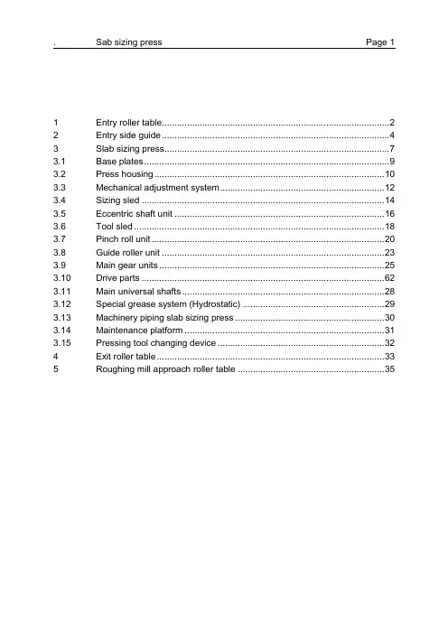
1Entry roller table (2)2Entry side guide (4)3Slab sizing press (7)3.1Base plates (9)3.2Press housing (10)3.3Mechanical adjustment system (12)3.4Sizing sled (14)3.5Eccentric shaft unit (16)3.6Tool sled (18)3.7Pinch roll unit (20)3.8Guide roller unit (23)3.9Main gear units (25)3.10Drive parts (62)3.11Main universal shafts (28)3.12Special grease system (Hydrostatic) (29)3.13Machinery piping slab sizing press (30)3.14Maintenance platform (31)3.15Pressing tool changing device (32)4Exit roller table (33)5Roughing mill approach roller table (35)1 Entry roller table2010 ArrangementThe roller table is located in front of the SSPFunctionThe roller table is capable of transferring the slabs through the sizing press either continuously during the slab approach to and the backward transport from as well as stepwise in operation of the press.The table will be designed for accommodating the entry side guide.Technical dataQuantity 1 unitType individually direct driven rollersRoller type solid rollers, roller barrel water cooled Table length approx. 11 640 mmRoller spacing 11 x 960 + 1 x 1 080mmNumber of rollers 13Roller diameter 450 mmBarrel length 2 050 mmRoller speed max. ± 2.2 m/sMotor dataRated power 16.5 kWSpeed 0 – 94 min-1 LRDescriptionRoller Type solid rollersRoll drive driven via one electrical motor per roller Roller bearings self-aligning roller bearingsBearing houses single-part design, cast steel or steel,fixed on table framesTable frames fabricated steel sectionsFixed side guides fabricated steel sections,attached to the roller table frame Aprons fabricated steel, grid type Crossbeams fabricated steelDrive shafts gear type couplingMotor bases fabricated steelPiping for- centralized grease lubrication of theroller bearings- roller barrel cooling by means of spraypipes2 Entry side guide2020 ArrangementThe entry side guide is located in front of SSPFunctionFor centering and measuring of the slab before entering the SSP.The side guides will be located in the area of the entry roller table and will be driven from one side by two hydraulic cylinders which are connected to the top carrier beams.They consist of a parallel centering section, which is attached to four carrier beams. The carrier beam pairs on drive and operator side are arranged above each other and synchronized via gear and tooth racks, the entry and exit side can be adjusted independently (for adjusting and measuring of transition slabs) and are synchronized via electrical controls. The carrier beams are supported via slide ways in the hous-ings on either side of the roller table.Thrust guides are arranged between the roller table frames and the side guides are equipped with bolted-on wear linersTechnical dataQuantity 1 unitGuides operate opening min. 800 mmmax. 2 100 mmShifting speed 100 mm/s on each sideLength of guides approx. 6 000 mmQuantity of cylinders 2Centering force approx. 600 kNCylinder dimensions Ø 140/100 x 800 mmHydraulic pressure 250 barDescriptionSide guides heavy fabricated steel constructionWear liners steel, bolted to the side guidesCarrier beams fabricated steel sections with bolted ontooth racks, gear racks quenched andtemperedHousings fabricated steel with incorporated bronzeliners for guiding of the carrier beams, lo-cated outside the roller table, housings ar-ranged on base frames, bearing blocks forsupporting the gear attached to the hous-ingsDrive actuated by 2 hydraulic cylinders, mount-ed onto the housings,Position control by position transducers installed in eachcylinder (please refer to M&C list)Piping for- centralized grease lubrication of thesliding liners & tooth racks- hydraulic cylinderReference DrawingGeneral arrangementSectional view3 Slab sizing pressArrangement and functionThe slab sizing press will be located between the roughing mill descaler and the roughing mill stand R1, for heavy width reductions of the slabs in one pass before rolling in the roughing mill.Technical dataType sizing press with pressing tools arrangedhorizontally and oppositely each other forstop-and-go advance of slabs through thepresspressing tools are oscillating continuouslyand simultaneously in the horizontal direc-tion and pressing the slab to a smallerwidth during closing. In the stop-and-gomode the slab will be advanced duringopening of pressing toolsWidth reduction 0 - 350 mm depending on:steel grade, slab width, temperature Pressing force max. 22 000 kNMain drive 1x 0 – 4 400 kW @ 0 - 600 min-1Pressing length max 428 mm per strokeNumber of strokes 42 strokes/minSlab advance speed max. 300 mm/sOpening of tools min. 655 mmmax. 2800 mm for free passagePressing tool adjusting drive 2x 0 - 440 kW @ 0 - 950 min-1Adjusting speed max. 44 mm/sec per sideReference image3.1 Base plates2040 ArrangementThe base plates are located below the separate equipment units of the SSP FunctionFor accommodation the following equipment units:•Press housing•Main gear box•Pinch roll drive•Main drive motor•Sizing sled push out device•Grease collecting systemTechnical dataQuantity 1 SetDescriptionBase plates fabricated steel construction &steel structure3.2 Press housing2050 ArrangementThe press housing consist of two horizontal mill housings connected by the housing separator and mounted on the base plates.FunctionFor accommodation of the following main equipment units:•Sizing & Tool sled•Eccentric shaft units•Mechanical scredown systemTechnical dataQuantity 1 SetDescriptionMill housing four-piece assembled design, made ofcast steel, horizontally arranged on thebase platesHousing separators heavy fabricated steel construction, boltedin between both housingsCross beam fabricated steel construction, arrangedbetween the bottom housing post withguide ways for dismantling of the presssleds, equipped with wear platesWear plates made of compound steel (55-60 HRC),Reference drawing3.3 Mechanical adjustment system2060 ArrangementArranged at both ends of the press housing.FunctionThe mechanical adjustment system in accordance with the balancing system serves for adjusting the sizing sled units for opening and closing the gap between the press-ing tools.Each mechanical adjustment system consists of two screwdown spindles which are mechanically synchronized and electrically driven via worm gears. Pneumatically op-erated disk brakes are arranged at the drive shafts. Both mechanical adjustment systems are electrical synchronized and moving horizontally.Technical dataQuantity 2 units (each unit: 2 spindels /3 cylinder) Pitch of thread 40 mmGear ratio 14,3DescriptionAdjusting screws forged steel, arranged in the press hous-ing, including nuts and thrust plates Worm gear units driving the adjusting screwsHydraulic balancing cylinders 1 for tool and 2 for sizing sled on eachsideLubrication gear boxes connected to centralized oillubrication system, coupling grease fillingReference drawing3.4 Sizing sled2070 ArrangementArranged on both ends inside of the press housing.FunctionEach sizing sled accommodate two eccentric shaft units and the tool sled, adjusted by the mechanical screwdown system for opening and closing the gap between the pressing tools.Technical dataQuantity 1 SetDescriptionSizing sleds cast steel, with guide ledges and holdingledges, with bearing parts and covers forthe accommodation of the eccentric shafts Clamping cylinders attached to the sizing sledsLubrication plain bearings connected to central greaselubrication systemReference drawing3.5 Eccentric shaft unit2080 ArrangementArranged in the sizing sled.FunctionDriven by the main universal shafts the eccentric shafts have the function to move forward and backward the pressing sled with the pressing tool.Technical dataQuantity 2 eccentric shafts per sizing sled80 mm eccentricityDescriptionEccentric shafts forged steel arranged in anti-friction bear-ings, sealed by labyrinth rings and sealingringsConnecting rods cast steel, accommodated in anti-frictionbearings on the eccentric shafts, sealedby labyrinth rings and sealing rings, plainthrust bearing shells of steel and retractingbolts for accommodation of the connectingrods in the pressing sledLubrication antifriction bearings connected to centralgrease lubrication systemplain bearings connected to the hydrostat-ic systemReference drawing3.6 Tool sled2090 ArrangementThe tool sleds with pressing tools and the bottom and top guide cross beams ar-ranged horizontally and oppositely to each other between the press housing posts with guide ways.FunctionDriven by the pair of eccentric shaft units and connected by a link to the sizing sled the tool sled accommondate the pressing tool and carry out the width reduction of the slab.Technical dataQuantity 1 SetTool dimension (approx)Width 400 mmThickness 350 mmLength 1700 mmDescriptionGuiding cross beams fabricated steel construction, arrangedbetween the press housing posts withguide ways for the tool sledTool sled cast steel, for accommodation of pressingtoolPressing tool special steel, attached to the tool sled,hydraulically releasable spring-loadedtensioning elements for clamping of thetools, cylinders for the turning of the rodsCooling of pressing tools width-dependent direct cooling of thepressing tools, as well as internal coolingof the pressing tool clamping platesLubrication plain bearings connected to central greaselubrication systemReference drawing3.7 Pinch roll unit2110 ArrangementThe pinch roll units arranged at the entry and exit side of the SSP are provided for driving the slab through the press.FunctionThe bottom rollers arranged stationary at the entry side and hydraulically adjustable in height at the exit side with regard to the operational conditions during pressing. Top rolls hydraulically adjusted to the slab. Each of these 3 rolls can be operated in position- / force control.Entry bottom and both exit rolls are electrical driven.Technical dataNumber of rolls top/bottom 2 / 2Roll diameter 520 mmBarrel length approx. 2 000 mmAdjustment force, max. 400 kNOpening max 440mm (between top and bottom PR) Motor power 1 x 192 kW (for each pinch roll pair) Speed 0 – 173 / 417 min-1Gear ratio 4,94Travelling speed max ± 2.2 m/secDescriptionPinch roll frame fabricated steel construction, arranged atentry and exit side sizing press housingposts, for accommodation of the pinch rollunitsPinch rollers made of special stainless steel, arrangedin anti-friction bearings, top roller featuringinternal & external and bottom roller ex-ternal water coolingPivot levers fabricated steel, for adjustment of top andbottom pinch rolls, arranged in plain bear-ings, fastened at the housing postsHydraulic cylinders (2) top and (1) bottom, for lifting and low-ering of the top pinch rolls and bottom exitpinch rollCylinder dimensions Ø 160/110 x 310 upper pinch rollsØ 200/140 x 110 lower pinch roll exit side Hydraulic pressure 250 barPosition control by position transducers installed in eachcylinder (please refer to M&C list)Drive unit the bottom entry roller is driven by onespur gear unit and universal joint shaft, topand the bottom exit rollers are driven viauniversal joint shafts, common distributiongear unit, motor couplings and electricalmotor (please refer to M&C list)Motor base frame steel constructionLubrication central grease lubrication: for bearingscentral oil lubrication: for gear boxes Machine piping for cooling water, lubrication, hydraulicsReference drawingSectional view3.8 Guide roller unit2120 ArrangementThe guide roller unit is arranged at the entry and exit side of the SSP inside of the press housing.FunctionUsed for guiding the slabs through the press, as well as for preventing of buckling of the slabs.The two top rollers are adjustable by hydraulic cylinders. Both bottom guide rollers with fixed arrangement.For the transport of slabs without pressing the bottom rollers are used as support rollers.Technical dataNumber of rolls top/bottom 2 / 2Roll diameter 800 mmRoll width approx. 340 mmAdjustment force, max. 400 kNOpening max 440mm (between top and bottom GR) DescriptionGuide rollers solid stainless steel rollers, arranged inanti-friction bearings, non-driven, topguide rollers internally & external and bot-tom guide rollers externally water cooledBearing housings fabricated steel construction, verticallyguided between wear ledges, vertical ad-just able by hydraulic cylinderGuide beams fabricated steel construction, fastened tothe top resp. bottom press housing posts,equipped with vertical guide ways for theaccommodation of the bearing housingsHydraulic cylinders 2 for top rollers adjustmentCylinder dimensions Ø 160/110 x 355 mmHydraulic pressure 250 barPosition control by position transducers installed in eachcylinder (please refer to M&C list) Lubrication centralized grease lubrication: bearingsMachine piping for cooling water,hydraulic equipmentReference drawing3.9 Main gear units2130 ArrangementAbove the slab sizing press on drive side and on operator side between the universal joint shafts to the eccentric shafts and the motor.FunctionTransmitting of torque and speed of the main drive motors via couplings, gear unit drive side, intermediate shaft, gear unit operator side and universal joint shaft. to the four eccentric shaftsTechnical dataQuantity 2 gear units per slab sizing pressGear ratio i = 14,448DescriptionGear housing welded steel structure with vertical parti-tion line in the shaft centers which arefixed by means of screw bolts, covers andoil collecting hoods, provided with inspec-tion covers, fastened on the foundationwith anchor boltsPinion shafts made of case-hardened steel with groundhelical toothing, resting in anti-frictionbearingsSpur gears made of case-hardened steel, with groundhelical toothingBevel gears made of case-hardened steelShafts made of heat-treated steel, resting in anti-friction bearingsMachine piping for lubrication on the machine up to thetakeover pointLubrication lubrication of the toothing and anti-frictionbearings by means of circulation oil lubri-cation, connection of the gear unit to acentralised oil lubrication system Reference drawingSectional viewTop view3.10 Drive parts2140 ArrangementAbove the slab sizing press, motor coupling on drive side between the motor and the main gear unit drive side and the intermediate shaft with tooth couplings between the both main gear unitsFunctionTransmitting of torque and speed of the main drive motors to the main gear unit be-tween the both main gear unitsTechnical dataQuantity 1 SetDescriptionMotor coupling tooth couplingLubrication manual grease lubrication systemIntermediate shaft made of steel, resting in antifriction bear-ingsIntermediate coupling tooth couplingLubrication lubrication of the toothing and antifrictionbearings by means of circulation oil lubri-cation, connection to a centralised oil lu-brication system3.11 Main universal shafts2150 ArrangementMain universal shafts as part of the complete drive system are arranged above the press housing between the two main gear boxes and the eccentric shafts.FunctionTransmitting of torque and speed of the main gear box output and the eccentric shaft units.Technical dataNumber of shafts 4Type of shaft Heavy universal shaft, cross-pin type Operating torque max. 630 kNmOperating speed 42 rpmCatalog functional limit torque appr. 2200 kNmDescriptionLubrication manual grease operation3.12 Special grease system (Hydrostatic)2160 ArrangementThe grease system for the hydrostatic of the SSP consists of 2 pump stations, each mounted to the sizing sled of the operator and drive sides.FunctionPermanently feed of special grease for the four connecting rod plain-bearing shells to insure hydrostatic lubrication condition.Technical dataType multichannel pumpQuantity 2 x 2 (1 operating, 1 stand-by)Operating pressure 350 barType of system special progressive systemType of grease special grease (BECHEM & RHUS FA50) Control & Monitoring Included in the system3.13 Machinery piping slab sizing press8804Arrangement- pipes mounted on steel structures which are arranged at the slab sizing press- bulkhead plates in the foundation area of the mill standFunctionPiping for feeding of the various fluids and media to the consumers, such as:- hydraulic fluid- lubrication fluids- water- compressed airBulkhead plates for:- closuring of the openings in the foundation area of the mill stand to the cellar- connection of the mill stand piping to the interconnecting piping in the mill stand areaTechnical dataQuantity 1 setPiping material: refer to 2.1.30.8.103.14 Maintenance platform2180 ArrangementArranged around the SSP on two levels.FunctionWalkway with access to certain sections of the SSP, accommodating of valve stands. Technical dataQuantity 1DescriptionMaintenance Platform welded steel plates and pipe structuresand stairs3.15 Pressing tool changing device2190 ArrangementArranged on the press housing, on each side above the sizing sled unit.FunctionThe tool change will be carry out via bay crane, tool changing car, lifting device and hydraulic valve stands in a semi-automatically mode.Technical dataQuantity 2 (one on each side)DescriptionLifting device please refer to special toolsTool changing car fabricated steel construction,with 2 vertical and 2 horizontal cylinders. Piping for hydraulic components4 Exit roller table2011 ArrangementThe roller table is located behind SSPFunctionThe roller table is capable of transferring the slabs from the sizing press either step-wise in operation of the press and continuously during the slab approach to the roughing mill stand and the backward transport from the roughing mill stand during reversing passes.Technical dataQuantity 1 unitType individually direct driven rollersRoller type solid rollers, roller barrel water cooled Table length approx. 5 250 mmRoller spacing 875 mmNumber of rollers 7Roller diameter 450 mmBarrel length 2 050 mmRoller speed max. ±3.0 m/sMotor dataRated power 22.5 kWSpeed 0 - 128 min-1 LRDescriptionRoller Type solid rollersRoll drive driven via one electrical motor per roller Roller bearings self-aligning roller bearingsBearing houses single-part design, cast steel or steel,fixed on table framesTable frames fabricated steel sectionsFixed side guides fabricated steel sections,attached to the roller table frame Aprons fabricated steel, grid type Crossbeams fabricated steelDrive shafts gear type couplingMotor bases fabricated steelPiping for- centralized grease lubrication of theroller bearings- roller barrel cooling by means of spraypipes5 Roughing mill approach roller table1590 ArrangementThe roller table is located between SSP exit roller table and roughing mill stand entry table.FunctionThe function of the roller table is to convey the slabs to the roughing mill stand. The table is capable of fast reversing and running synchronised with the mill stand in both forward and reverse direction.Technical dataQuantity 1 unitType individually direct driven rollersRoller type solid rollers, roller neck water cooled Table length 11 700 mmRoller spacing 900 mmNumber of rollers 14Roller diameter 450 mmBarrel length 2 050 mmRoller speed 0 ± 3.5 m/sMotor dataRated power 20 kWSpeed 0 – 149 min-1 LRDescriptionRoller Type solid rollersRoll drive driven via one electrical motor per rollerRoller bearings self-aligning roller bearingsBearing houses single-part design, cast steel or steel,fixed on table framesTable frames fabricated steel sections Crossbeams fabricated steelFixed side guides fabricated steel sections,attached to the roller table frame Aprons fabricated steel, grid typeDrive shafts universal spindlesMotor bases fabricated steelLubrication roller bearings lubricated by centralizedgrease lubricationRoller neck cooling water cooling by means of spray pipes1 入口辊道 (2)2 入口侧导板 (4)3 定宽机 (7)3.1 基底板 (9)3.2 外壳 (10)3.3 机械调整系统 (12)3.4 定宽滑块 (14)3.5 偏心轴装置 (16)3.6 工具滑板 (18)3.7 夹送辊装置 (20)3.8 导辊装置 (23)3.9 主齿轮装置 (25)3.10 传动件 (62)3.11 主万向轴 (28)3.12 特殊油脂系统(流体) (29)3.13 定宽机的机械管道 (30)3.14 检修台 (31)3.15 冲压工具更换装置 (32)4 出口辊道 (33)5 粗轧机输入辊道 (35)6入口辊道2010 布置辊道位于定宽机前功能该辊道既可连续输送板坯通过定宽机,也可在操作定宽机时逐步的反向输送。

