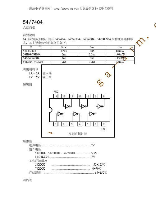
h04
- 格式:ppt
- 大小:15.50 KB
- 文档页数:6


电子病历基本架构与数据标准征求意见稿卫生部信息化工作领导小组办公室卫生部卫生信息标准专业委员会二○○九年七月目录一、前言 (4)二、电子病历的基本概念和体系架构 (5)(一)基本概念 (5)(二)体系架构 (6)三、电子病历的基本内容和信息来源 (7)(一)基本内容 (7)1、病历概要 (7)2、病历记录 (8)3、转诊记录 (10)4、法定医学证明及报告 (10)5、医疗机构信息 (10)(二)信息来源 (10)四、电子病历数据标准 (13)(一)标准化原则 (13)(二)数据标准 (14)1、电子病历信息模型 (14)2、电子病历数据组与数据元标准 (17)3、电子病历基础模板与数据集标准 (20)一、前言《中共中央国务院关于深化医药卫生体制改革的意见》和《国务院关于印发医药卫生体制改革近期重点实施方案(2009-2011年)的通知》中明确提出:大力推进医药卫生信息化建设。
将“打好三个基础、建好三级平台、提升业务应用系统”作为当前医药卫生信息化建设的重点。
其中“打好三个基础”一是建立全国统一的、标准化的居民健康档案;二是建立国家电子病历的基本架构与数据标准;三是建立国家卫生信息数据字典。
在加强我国卫生信息标准化建设基础上,重点推动以健康档案和电子病历为基础的区域卫生信息平台建设,并提升业务应用系统,构建各级各类医疗卫生机构之间的信息共享和联动服务机制,实现区域卫生协同,惠及居民。
按照医药卫生体制改革的总体要求,近年来卫生部信息化工作领导小组办公室、卫生信息标准专业委员会、统计信息中心等部门组织有关业务单位、院校和大批专家开展了一系列国家卫生信息标准基础与应用研究,目前已取得多项重要成果。
其中,《健康档案基本架构与数据标准(试行)》和《基于健康档案的区域卫生信息平台建设指南(试行)》已于2009年5月由卫生部正式印发试用。
从国家卫生信息化发展规划的战略高度,指导各地居民健康档案和区域卫生信息平台的标准化、规范化建设,为进一步优化、提升各类卫生业务应用系统奠定基础。


JB-QB-ODH04Conventional Fire alarm Control Panel INSTALLATION and OPERATION MANUALNOTICEAll information, documentation and specification contained in the manual are subject to change without prior notice by the manufacturer.©2010 By Shenzhen Orena Photonic Technology Co.,Ltd.ODH04 Ver 1.0Table of ContentsCHAPTER 1: P roduct Description (1)1.1 Product Features (1)1.2 Specifications .......................... .. (2)1.3 Controls and Indicators (2)1.4 Circuits (4)1.5 Components (5)CHAPTER 2: Installation (6)2.1 Mounting Options (6)2.2 Backbox Mounting (6)2.3 Operating Power (7)2.4 Input Circuits (7)2.5 Output Circuits (8)CHAPTER 3:Operating Instructions (9)3.1 Key Functions in Normal Mode (9)3.2 Status of LEDs (10)3.3 Operation (11)3.3.1 Fire Alarm Response (11)3.3.2 Fire Alarm Restoral (12)3.3.3 Fault Condition Response (12)3.3.4 Fault Condition Restoral (12)CHAPTER 1: Product DescriptionThe ODH04 is a 1-zone to 4-zone FACP(Fire Alarm Control Panel), controlled by microprocessor, according to the current national standard GB4717-2005 . The panel is able to be connected with conventional two-wire smoke detectors, two-wire heat detectors, call points and other normally-open contact devices. The FACP supervises all wiring, AC voltage and battery level.1.1 Product Features●Connected with conventional detectors and normally open circuit device●One Alarm Relay●One Trouble Relay●Manual Call point alarm● 2.2 amps of system power●Max 30 conventional detectors in one zone●Manual active sound output enabled.●Able to display short and broken circuit of detection zones.●Designed with standby batteries and space provision for two sealed lead-acid batteries.●Testing functions.FIGURE 1.1: ODH04 Circuit BoardODH04 Terminals and Connectors1.2 SpecificationsAC PowerAC187V~AC242V 50Hz±1HzBattery(lead acid only)Maximum Charging Circuit: Normal Flat Charge—27.6V@0.8 ampOutput Device CircuitsGeneral Alarm Zones 1 through 4Operation: All zonesNormal Operating Voltage: Nominal 28VDCShort Circuit Current: 42mA MaximumMaximum Loop Resistance: 100 ohmsEnd-of-Line Resistor: 5.1K, 1/4 wattDetector loop current is sufficient to ensure operation of two alarmed detectors per zone Two Relays outputRelay contact rating: 1.0 amps @ 28VDC(resistive)Nonresettable 28VDC PowerMaximum ripple voltage: 20 mV RMS Operating Voltage nominal: 28V Total DC current available from this output is up to 2.2AOperating EnvironmentTemperature: 0~55℃Relative humidity: ≤95%(40℃±2℃)Dimension: 370mm x 240mm x 60mm1.3 Control and indicatorsFront Panels keys in Normal Mode●FUNCTION/ENTER●SOUNDER●SELF CHECK / +●F1/ —●RESET/●SILENCELEDs●FIRE - red LED●FAULT - yellow LED●SYSTEM FAULT - yellow LED●SELF CHECK - yellow LED●SOUNDER INDICATE - red LED●SOUNDER FAULT - yellow LED●AC POWER - yellow or green LED●BATTERY - yellow or green LEDLocal SounderA sounder provides separate and distinct sound for fire alarm and trouble conditions:●Fire Alarm- pulse 0.3 second On and 0.3 second off●Fault- pulse 0.8 second on and 4 second offFigure 1.3.1: ODH04- 4 ZONE LEDS and KeypadFigure 1.3.2: ODH04- 2 ZONE LEDS and Keypad1.4 CircuitsInput Circuits4 input circuits provide configuration. Input circuits 1 through 4 may be used as standard fire alarmcontrol panel zones. All 4 initiating device circuits accept normally-open contact devices andtwo-wire detectors.Output Circuits28 Volt Nonresettable Power output 1500 mA28 Volt Battery Charger (up to 7 AH batteries)RS-485 Port (interfaces to Annunciators)Sound CircuitsOne Notification Appliance CircuitRelaysTwo dry relays for system alarm, system trouble are provided standard. Contacts are rated 1.0 amps @28 VDC(resistive)and 1.0 amps @ 110VAC(resistive).RS-485 PortRS-485 compatible port supports up to 4 different device addresses which can consist of remoteannunciators.Battery ChargerBattery charger will charge up to 2.2 AH batteries. he external box is required to hold 7 AHbatteries. The charger is rated for 500mA maximum current.1.5 ComponentsMain Circuit BoardThe main circuit board contains CPU, other primary components and wiring interface connectors.Optional modules plug in and are mounted to the main circuit board. The main circuit board is delivered pre-mounted in the cabinet.Terminal Circuit BoardThe terminal circuit board contains 4 input circuits ,sound circuits, wiring interface connectors and other primary components, is delivered pre-mounted in the cabinet.Power Supply Circuit BoardThe Power Supply circuit board contains battery charger circuit, AC power supply and battery testing circuit and wiring interface connectors,.CabinetThe cabinet is blue and the backbox measures 370mm long X 240mm high X 600mmdeep and provides space for two batteries( 2.2 Amp Hours).Power Module AssemblyOne 70VA power module is provided standard with the panel.BatteriesThe cabinet provides space for 2.2 Amp hour batteries(large batteries up to 7 Amp Hour batteries, use the external battery box). Batteries must be ordered separately.Chapter 2: Installation2.1 Mounting OptionsThe cabinet may be either semi-flush or surface mounted. The cabinet mounts using three keyholes.Carefully unpack the system and check for shipping damage. Mount the cabinet in a clean, vibration-free area where extreme temperatures are not encountered. The area should be readily accessible with sufficient room to easily install and maintain the panel. Locate the top of the cabinet approximately five feet above the floor. All wiring should be in accordance with the National and/or Local codes for fire alarm systems.2.2 Backbox Mounting✓Open the door✓Mark and predrill holes for the top two keyhole mounting bolts using the dimensions illustrated.✓Install two upper fasteners in the wall with the screw heads protruding.✓Using two upper keyholes, mount the backbox over the two screws.✓Mark and drill the lower one holes.✓Mount backbox, install remaining fasteners and tighten.Figure 2-2 - Cabinet dimensions and knockout locations2.3 Operating PowerPrimary Power Source(AC)AC power connections are made inside the control panel cabinet. The primary power source for the ODH04 is 220VAC, 50Hz, 2.2 amps. Connect power supply wire to the CN1 terminal of the power supply board.Secondary Power Source(Batteries)Observe polarity when connecting the battery. Connect the battery cable to the CN3 terminal of the power supply board using the plug-in connector and cable provided.Figure 2-3: Typical operating power connections2.4 Input CircuitsThe control panel has 1-4 zone input circuits. The maximum loop resistance limit for each input circuit is 100 ohms. All field wiring of each zone is displayed for faults. Both conditions are visually and audibly annunciated.Each zone is a device circuit designed to accept any normally-open contact devices and conventional 2-wire, 28 volt smoke detectors.All zones may be configured for general fire alarm applications.It is allowable to mix an assortment of device types (i.e. smoke detectors, heat detectors, call points, etc.) on any zone.Figure 2-4: Initiating device circuit connections2.5 Output CircuitsDC Power Output ConnectionsNonresettable Power(1500 mA) 28VDC filtered, nonresettable power can be obtained from terminal 28V (+)and (-).Figure 2-5-1: Initiating device circuit connectionsNotification Appliance CircuitsThe ODH04 provides one notification appliance circuit standard. Each circuit is capable of 2.0 amps of current. Total current draw n from these as well as other DC power output can’t exceed 2.2 amps with the standard transformer. Circuits are supervised.Standard RelaysThe control panel provides two relays rated for 1.0 amps @28 VDC(resistive) and 1.0 amps @ 120VAC(resistive)Figure 2-5-2 : Relay terminalsBase Detection ZoneDetection ZoneBaseEnd of Line ResistorChapter 3: Operating InstructionsFigure 3-1-1 Led indicators and KeypadUpon initial power-up, the system will be on Normal Mode. This section discusses operation of the control panel in the Normal Mode.3.1 Key Functions in Normal ModeFigure 3-1-2: Led indicators and KeypadFUNCTION/ENTERPassword "119 " should be entered. Press "+" and "-" to adjust the number. Press "<-" and "->"to move the cursor. Press FUNCTION/ENTER to confirm it. if the password you entered is wrong, it will display "Please enter the password". Press "<-" to return to the normal mode.SOUNDERSilencing/resounding the soundersSELF CHECKIf the key is pressed, the unit will perform a lamp test. All panel LEDS will be turned on. Output contact and sounder strobe will not be activated. The buzzer will beep.F1If the key is pressed, The current fire event can be inquired. If it displays 08:31 and it means that there isa fire event at that time. Press "->" and it displays 08:34 and it means that there is another fire event atthat time. Press “<-”, it returns to the normal mode. If press "F1", it displays and it means that there is no fire event. Press “<-”, it returns to the normal mode.RESETThe system key resets the system, any detectors and annunciators. A RESET key is located on keypad (illustrated in Figure 3-1). If the System RESET keys are pressed, the control panel will:√ Clear the status of LEDs√ Turn off the Notification Appliance Circuits√ Reset all zones by temporarily removing power√ Silence the onboard sounder√ Restore all system relays to normal√ Temporarily remove power from the resettable power output terminalsSILENCEIf the key is pressed, the buzzer will be silenced.3.2 Status of LEDsFIRE LEDA red LED that turns on when a system fire alarm condition is detected.FAULT LEDA yellow LED that turn on to indicate that a system fault or abnormal condition exists and that thefire alarm system may be inoperative. It turns on steady when a signal SILENCE key is pressed.SYSTEM FAULT LEDA yellow LED that remains on while the panel has some faults.SELF CHECK LEDA yellow LED that turn on to indicate that a system is in the process of testing unless there is a fire inother zone or after 5s.SOUNDER INDICATE LEDA red LED that turn on to indicate that the corresponding Notification Appliance Circuits isactivated. It turns off when the SOUNDER key is pressed.SOUNDER FAULT LEDA yellow LED that turns on to indicate that one or more Notification Appliance Circuits have fault.AC POWER LEDA green LED that remains on while the AC power supply is within correct limits. A yellow LEDRemains on under battery powered condition. It turns on steady when SILENCE key is pressed. Ifthis indicator fails to light under normal conditions, service the system immediately.BATTERYA green LED that remains on while the battery power supply is within correct limits. A yellow LEDRemains on to indicate a low battery condition on the ODH04. It turns on steady when SILENCEkey is pressed. If this indicator fails to light under normal conditions, service the systemImmediately.ZONE 1- 4 FIRE LEDRed LEDs remains on to indicate that an alarm exists on the corresponding zone. It turns oneady when SILENCE key is pressed.ZONE 1- 4 FAULT LEDYellow LEDS remains on to indicate that a fault or abnormal condition exist on the correspondingzone. It turns on steady when SILENCE key is pressed.ZONE 1- 4 MANUAL ALARMA red LED remains on to indicate that a manual call points is activated. It turns on steady whenSILENCE key is pressed.3.3 OperationNormal mode is the standard mode of operation. Under this mode, the panel continuously monitors system status. The notification appliance circuits will be off, all relays are in their normal state and the onboard sounder will be off.All alarms and system faults conditions are annunciated on the control panel's LEDs. The control panel will inquire a "last event list" which will consist of all alarms and system faults currently active and not cleared, requiring immediate service. When the system is cleared and restored to normal, the LEDs will be off except for the AC POWER LED AND BATTERY LED and status LED.Higher priority events take precedence over lower priority events. Display and reporting of system status is done on a priority basis. Priority are, From highest to lowest:1. Alarms2. System Faults3.3.1 Fire Alarm ResponseUpon detection of an alarm condition, The control panel will cause the following:●Turn on the FIRE LED●Turn on the Notification Appliance circuits●Turn the sounder on steady●Turn on alarm relay.●The buzzer will beep●Transmit fire information to annunciators.3.3.2 Fire Alarm RestoralThe control panel returns to normal after a system reset key has been pressed (Call points have been reset, smoke detectors have been reset and no smoke is present). The control panel will perform the following upon restoral of all alarms:●Turn off the FIRE LED●Turn off the ZONE FIRE LED●Turn off the notification appliance circuits●Turn off the sounder●Turn off appropriate zone relay output●Turn off alarm relay●The buzzer will be off●Transmit reset information to annunciators3.3.3 Fault Condition ResponseThe control panel will perform the following upon detection of one or more fault conditions:●Turn on the FAULT LED●Turn on the ZONE FAULT LED if fault condition is on the zone●Activate fault relay●The buzzer will beep●Transmit fault information to annunciators3.3.4 Fault Condition Restoral●Shut off the FAULT LED●Shut off the ZONE FAULT LED(S)●Deactivate the fault relay●The buzzer will be off●Transmit restoral information to annunciators。