腔体滤波器设计
- 格式:ppt
- 大小:2.09 MB
- 文档页数:65

腔体滤波器结构
腔体滤波器是一种常见的微波滤波器,其结构通常由一路或多路独立的滤波器单元组成,主要包括腔体、盖板、连接器、传输主杆、电容耦合片、低通、谐振器、调谐螺杆(即调谐自锁螺钉)、电容耦合杆、介质、紧固螺钉等零部件。
其中,腔体是滤波器结构的主要部分,通常由金属整体切割而成,结构牢固。
这种滤波器通常具有良好的性能,如较高的Q值、优良的散热性等。
此外,由于其体积较小,这种滤波器也适用于小型化的应用,如Massive MIMO
有源天线。
以上内容仅供参考,建议查阅关于腔体滤波器的书籍或者咨询相关技术专家,获取更全面和准确的信息。
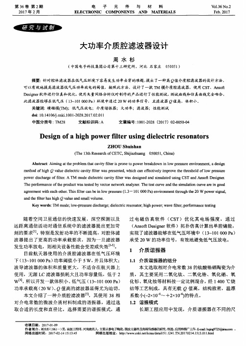
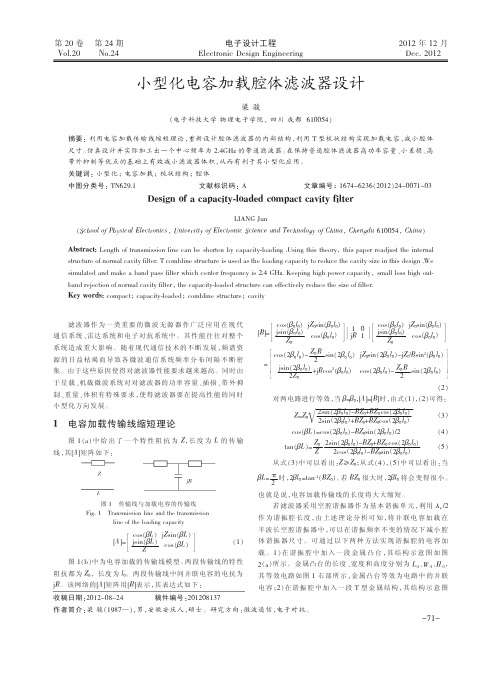
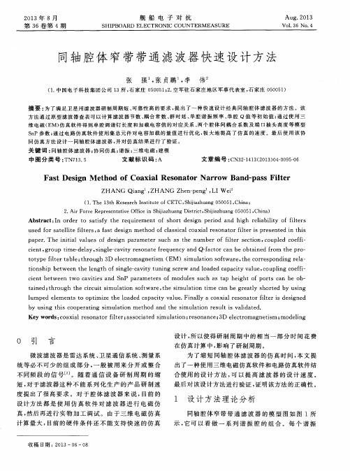
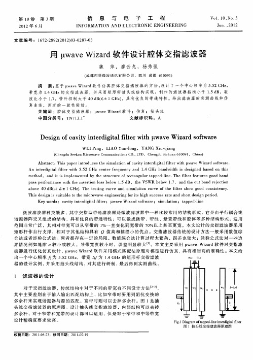
High Performance Helical Resonator FiltersMing Yu and Van DokasCOM DEV Ltd, 155 Sheldon Dr., Cambridge, Ontario, Canada, N1R 7H6ming.yu@Abstract — Complex filter functions are realized using cross-coupled helical resonators. Internal group delay equalization and multiple transmission zeros are implemented through the design, fabrication and test of a 7-1 and 8-2-2 filter. Excellent filter responses are achieved.Index Terms — helical resonators, cross coupled band pass filters, helix, group delay equalizationI. I NTRODUCTIONHelical resonator filters [1, 2] are widely used in ground based UHF mobile communication systems. They exhibit reasonable Q and excellent in-band performance over a wide temperature range with less volume and mass compared to conventional coaxial cavity filters operating in this band. Helical resonator filters are best suited in applications where conventional lumped-element filters are very small but are too lossy (lower Q) and coaxial resonator filters (higher Q) are too big and unpractical. Compared to SAW filters, although much bigger, the helical approach is much simpler and requires no costly fabrication setup. Small quantities can be produced economically with quicker delivery. This type of filter becomes particularly attractive for satellite applications where low volume and mass coupled with high reliability and electrical performance is a must. The most common filter functions realized with helical resonator technology are either Butterworth or Chebyshev without prescribed transmission zeros as extensively summarized in [1]. Low order (n=4) cross coupled filter, used in dual degenerate mode [3-5], gives further size and mass reduction with slightly lower Q and reduced spurious clean window. Further, cross-polarization stray couplings in dual-mode configurations prevents realizing complicated and high performance filter functions such as 8-pole with internal group delay equalization using many transmission zeros. Although a circulator coupled external equalizer can be used with a dual mode filter that often leads to unnecessary increase in mass and volume.In this paper, high order helical resonator filters are investigated to achieve very stringent performance required in communication satellites including sharp rejection response and group delay equalization. By utilizing the advances in the area of electromagnetic optimization [6] and computer aided tuning [7], a 7-1 and 8-2-2 filter were designed to meet satellite industry specifications. The filters were manufactured, tuned and tested. Results are presented in this paper. To the best our knowledge, this is the first time that such complex filter functions have been realized using helical resonators.II. H ELICAL RESONATORThe typical configuration of a helical resonator is shown in Figure 1 (inside a rectangular metal cavity). The resonator is mounted at 0.1inch above the floor of a 12x0.7inch cavity. Using quarter-wavelength (λ/4=8.57inch at 344MHz) as a starting point, it leads to a coil diameter of 0.65inch with 4.2 turns. The dimensions can be quickly verified using an EM eigen mode solver, as given in table 1. It is interesting to note that the manual calculation is as accurate as EM mainly because the frequency is relatively low. This also reveals that the effect of cavity loading on frequency is relatively small. The first spurious mode is projected to propagate just above 1GHz when the length of the wire reaches 3λ/4.Figure 1. EM model of a Helical ResonatorThe simulated Q is about 1250. A single copper cavity helical resonator has been measured. The measured Q is 1000 and first spurious response is around 1GHz.The similar simulation was performed for another resonator at about 600MHz. The cavity size is 0.852x0.6.A helical resonator with diameter of 0.65inch and 3 turns was selected.III. FILTER DESIGNThe first filter designed is a 7-pole with one transmission zero at low side (7-1). The center frequency is 307MHz and the bandwidth is 35 MHz. The normalized coupling matrix with input and output termination is shown in Table 2. R1 and R7 are magnetically coupled using a wire connected directly from I/O connector to the corresponding resonators. The coupling m3,5 is realized using φ0.04 inch cross coupling probes. The rest of inter-cavity couplings are realized using 0.75inch wide irises with various depths.Table 2. Normalized coupling matrix for 7-1 filterR1 = 1.1332m1, 1 = 0.0123 m2, 2 = 0.0019 m3, 3 = -0.0607 m4, 4 = 0.1147 m5,5 = -0.1027 m6, 6 = -0.0503 m7, 7 = -0.0075 R7 = 1.1774m1 ,2 = 0.8896 m2 ,3 = 0.6150 m3 ,4 = 0.5678 m4 ,5 = 0.5690 m5 ,6 = 0.6175 m6 ,7 = 0.8985 m3 ,5 = -0.1103The second variant designed is a 8-pole filter with two transmission zeros and two real zeros used to equalize in-band group delay. Within 60% of the pass band, the group delay and loss variation are designed to exhibit a very flat response. The center frequency (CF) is 598MHz and the bandwidth (BW) is 36MHz. The normalized coupling matrix is shown in Table 3. The inter-cavity couplings are realized using 0.58inch wide irises with various depths. The m1,8 iris width is 0.25inch. The m2,7 coupling is realized using a coupling wire (φ0.02inch) connecting the 2nd and 7th resonators.The tap point, which determines the coupling bandwidth (CBW) and Ri, is derived using a well-known S11group delay (GD) technique [8]:GDBWRCBWi•=•=π2Table 3. Normalized coupling matrix for 8-2-2 filterR1 = 0.9622m1, 1 = 0.0207m2, 2 = 0.0196m3, 3 = 0.0206m4, 4 = 0.0275m5,5 = 0.0026m6, 6 = 0.0065m7, 7 = 0.0163m8, 8 = 0.0204R8 = 0.8262m1 ,2 = 0.8166m2 ,3 = 0.5849m3 ,4 = 0.5422m4 ,5 = 0.5817m5 ,6 = 0.5333m6 ,7 = 0.5608m7 ,8 = 0.749m1,8 = 0.0166m2,7 = -0.0679The inter-cavity coupling can be determined by solving the eigen value problem of a 2-cavity coupled model [9]:2222,memej i ffffBWCFM+−•=Where f e and f m represent the resonant frequencies assuming symmetric plane to be perfect electric conductor (PEC) and magnetic conductor (PMC).Figure 2 and 3 show the construction of the 7-1 and 8-2-2 filters. The dimensions of the copper filters are about 4.4x2.3x1.4inch and 4.2x2.1x1.2inch respectively.IV. MEASURED AND SIMULTED DATAFigure 4 shows the measured/simulated return loss and insertion loss of the 7-1 filter. The “noisy” trace is the measured data (typical with all plots in this paper). The measured spurious response at 1GHz shown in figure 5 is caused by the 3λ/4 resonance. It implies that another higher order mode helical filter can also be realized at 1GHz (the EM simulation predicted a similar Q as λ/4 resonator at 307MHz). Figure 6 shows the in-band loss variation of the 7-1 filter. The measured insertion loss of the copper filter is about 0.5dB, which represents a Q of approximately 800. All measured data agrees very well with the simulations.Figure 7 shows the measured/simulated return loss and insertion loss of the 8-2-2 filter. Figure 8 shows the in-band loss variation. The measured insertion loss from a copper filter is about 0.9dB, which represents a Q of 1100. The measured and simulated group delay performance is illustrated in Figure 9. Again all measured data agrees very well with the simulated data.Both filters were later fabricated using silver plated aluminum cavities meeting satellite hardware standards. The frequency drift over a 75o C delta is about 4ppm using 8ppm coil material.VII. C ONCLUSIONHigh performance cross-coupled filters using helical resonators are presented in this paper. A 7-1 and 8-2-2 prototype was designed, built and tested using full-electromagnetic simulation techniques. To the best our knowledge, this is the first time that such complex filter functions have been realized using helical resonators. Excellent in-band loss variation, group delay and out-of-band rejection have been demonstrated to meet the stringent specifications of satellite communication systems. Measured data correlates very well with simulated data.VII. A KNOWLEDGEMENTThe authors wish to acknowledge the useful discussion with Mr. Peter Vizmuller during the concept design stage of one of the filters.R EFERENCES[1] Peter Vizmuller, “Filters with Helical and FoldedHelical Resonators”, Artech Hose, Inc. Norwood, MA, 1987,[2] Everard, J.K.A.; Cheng, K.K.M.; Dallas, P.A.; “High-Q helical resonator for oscillators and filters in mobilecommunications systems”, Electronics Letters , Volume: 25 , Issue: 24 , 23 Nov. 1989 Pages:1648 – 1650[3] Fiedziuszko, S.J.; Kwok, R.S.; “Novel helicalresonator filter structures”, Microwave Symposium Digest, 1998 IEEE MTT-S International , Volume: 3 , 7-12 June 1998, Pages:1323 - 1326 vol.3[4] Kwok, R.S.; Fiedziuszko, S.J.; “Dual-mode helicalresonators”, Microwave Theory and Techniques, IEEE Transactions on , Volume: 48 , Issue: 3 , March 2000 Pages:474 - 477[5] R. Levy and K. Andersen “An optimal low loss HFdiplexer using helical resonators”, Microwave Symposium Digest, 1992., IEEE MTT-S International, 1-5 June 1992, Pages:1187 - 1190 vol.3 [6] M. A. Ismail, D. Smith, A. Panariello, Y. Wang andM. Yu, “EM Based Design Of Large-Scale Dielectric Resonator Filters And Multiplexers By Space Mapping”, IEEE Transactions On Microwave Theory And Techniques Special Issue on Electromagnetics-Based Optimization of Microwave Components and Circuits, Vol.52, Jan. 2004, pp386-392[7] Ming Yu, (Invited) “Simulation/Design Techniquesfor Microwave Filters - An Engineering Perspective”, Workshop WSA: State-of-the-Art Filter Design using EM and Circuit Simulation Techniques”, International Symposium of IEEE Microwave Theory and Tech, May 2001, Phoenix AZ[8] J.B. Ness,"A unified approach to the design,measurement, and tuning of coupled-resonator filters", IEEE Transactions on Microwave Theory and Techniques, Vol.46, Apr 1998. pp. 343-351[9] M. E. Sabbagh, K. Zaki, and Ming Yu,“Full-WaveAnalysis of Coupling between Combline Resonators and its Application to Combline Filters with Canonical Configurations" IEEE Transactions on Microwave Theory and Techniques, Vol. 49, No.12, December, 2001, pp2384-2393.Figure 2. Photo of a 7-1 helical filterFigure 3. Photo of a 8-2-2 helical filter。