水控充值系统B-使用说明书
- 格式:doc
- 大小:578.50 KB
- 文档页数:18
东莞市西奥计算机智能科技有限公司K9水控机使用说明书2010年04月20日VER 1.0目录第一章产品概述 (2)1.1系统特点 (2)1.2水控机外观介绍 (2)1.2.1 外型介绍 (2)1.2.2 各部分功能说明 (2)1.2.3 按键介绍........................................................................................................................ 错误!未定义书签。
1.2.4 按键功能说明 (2)1.4水控机参数及特征 (3)1.4.1 水控机参数 (3)1.4.2 功能特征 (3)第二章设备安装 (3)2.1设备连接 (3)2.1.1 接口定义 (3)2.1.2 电源连接 (4)2.1.3 电磁阀连接 (4)2.1.4 流量计连接 (4)第三章参数设置 (5)3.1功能参数设置 (5)3.2系统密码设置 (5)3.3数据采集 (6)3.4消费操作 (6)第四章系统配置及使用流程 (7)第一章 产品概述K9水控机是西奥科技有限公司自主研发的新一代IC 卡节能节水自动控制系统,产品采用先进的生产工艺,挂式安装,密封性好。
1.1 系统特点。
1.2水控机外观介绍1.2.1 外型介绍1.2.2 各部分功能说明1.电源指示灯:电源接通后即点亮指示;2.读卡指示灯:感应到卡,灯常亮,工作状态时,闪烁点亮;3.LED 显示屏:八位LED 数码管,待机状态时,显示机器机号。
在刷消费卡时,显示卡上余额。
4.插卡槽:插放用户卡;5.按键:含有启动/暂停键、功能键、上调键、下调键等;1.2.3 按键功能说明水控机按键正常消费输入金额外,还可以设置部分参数功能。
具体的功能说明如下: 启动/暂停键 :在读卡有效的情况下,按下该键,水控机开始工作,再次按,暂停工作;功能键:按该键,在5秒钟内,按下调键,查看设备序列号,按上调键,查看设备版本信息;刷密码卡,可以加载密码及设置读卡扇区信息。
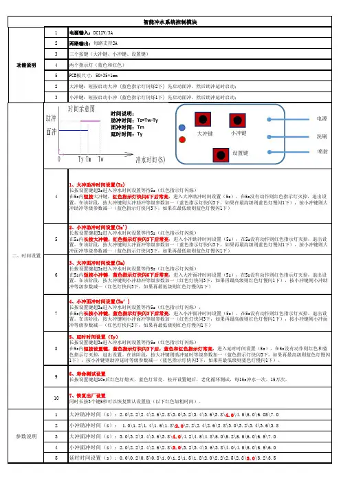
41、大冲助冲时间设置(Tz)
长按设置键超3s进入冲水时间设置等待5s(红色指示灯闪烁)
在5s内短按大冲键,红色指示灯快闪6下后常亮,进入大冲助冲时间设置(5s),在5s没有动作则红色指示灯灭掉,退出设置。
在该阶段,按大冲键则大冲助冲等级参数加一(蓝色指示灯快闪3下,如果在最高级则蓝色灯慢闪1下),按小冲键则大冲助冲等级参数减一(蓝色指示灯快闪3下,如果在最低级则蓝色灯慢闪1下)
2、小冲助冲时间设置(Tz')
长按设置键超3s进入冲水时间设置等待5s(红色指示灯闪烁)
时间说明:
助冲时间:Tz=Tw-Ty
面冲时间:Tm
延时时间:Ty。
水控机硬件功能说明一、水控系统独立使用使用独立水控软件—CFJN,水控金额写入IC卡独立的分区,从管理电脑上存款;管理软件根据数据回收方式可设置为三种运作模式即:不回收、采集卡回收。
当管理人员选择其中一种运作模式时,其相应的菜单同时会显示于操作软件界面的菜单上。
二、水控机和收费系统一起使用当水控机应用收费系统管理软件时,可根据水控金额来源划分为两种模式即:收费系统、由收费转入。
当采用“收费系统”时:水控金额和收费系统用同一区,水控机必须使用联网机型---W690M,回收消费数据。
当采用“由收费转入”时:水控金额采用独立的分区,金额由收费系统的收费金额通过水控转款机转到该区,不联网、不回收消费数据。
三、水控系统基本配置:管理电脑、打印机、RS485或TCP/IP转换器、发卡机、水控管理软件(与收费一起用时采用收费管理软件)、感应卡、水控机(一体机自带电磁阀、流量计,不联网;分体机还需选择阀体及是否联网等)、电磁阀或电动阀(分体机用)、流量传感器(分体机计量方式时选用)、水控授权/转款机(与收费一起使用,金额由收费转入即不联网时选用)、其它配件。
水控机显示有多种,版本不同可能有不同的显示0 ~ 9:开机自检J XXX:水控机机号C XX:水控机内消费总次数XX.XX:水控机内消费总金额U__X.XX:水控机版本号CJ—XXX:水控机型号┣XX-XX:水控机日期XX—XX:水控机时间。
:水控机未初始化(用参数卡)。
:读卡模块自检未通过―――:水控机处于工作模式,下横为模式一、中横为模式二、上横为模式三P :P在左为左龙头,P在右为右龙头;收费机机处二于红外暂停状态四、水控特殊卡说明:1、系统卡使用系统卡用于初始化水控机,清除机内消费金额、消费人次。
将系统卡放在水控机感应区,水控机显示“SE”并很快显示“CF”即表示初始化成功;拿开系统卡,此时“CF”会显示几秒钟即显示正常收费状态“---”下。
2、参数卡水控机通过参数卡来传递水控参数的,在系统管理软件中设置好参数,参数卡向水控机传递的水控参数(参数卡所设置的功能项可参考相应的管理软件)。
. . IC卡(射频卡)收费系统之DTK—W100型DTK—W200型61.智能节水控制器简介 (2)1.1DTK—W100型节水控制器结构图 (3)1.2 DTK—W200型节水控制器结构图 (4)2. 智能节水控制器原理及操作流程 (5)2.1 智能节水控制器原理 (5)2.2 DTK—W100型节水控制器操作流程图 (5)2.3 DTK—W200型节水控制器操作流程图 (6)3. 智能节水控制器功能 (7)3.1 DTK—W100型节水控制器 (8)3.2 DTK—W200型节水控制器 (9)3.3 初始化显示 (12)3.4 管理卡的设置 (14)3.5 常见问题的解决方法 (16)4. 智能节水控制系统组成 (18)4.1 系统硬件和软件组成 (18)4.2 智能节水控制器组成 (18)5. 附件构成 (19)5.1 电动阀 (19)5.2 电磁阀 (20)5.3 电源 (21)5.4 读写器 (22)6. 网络安装 (23)6.1 系统结构图 (23)6.2 系统安装接线图 (23)6.3 浴室安装示意图 (24)6.4 开水房安装示意图 (25)6.5 墙正视图 (25)7.电动阀和电磁阀安装接线图 (26)7.1 线的接法: (27)7.2 选择阀门的跳线接法: (32)1.智能节水控制器简介DTK—W100型和DTK—W200型智能节水控制器是我公司自主开发、研制成功、并被广泛使用的高新技术产品。
智能节水控制器集读卡、显示、自动收费以及报警功能于一体,外型美观、人性化设计,具有防潮、防水、抗干扰、使用方便等特点。
1.1DTK—W100型节水控制器结构图DTK—W100型结构说明①外壳……………产品包装壳②螺丝钉……………固定壳体③放卡出水区……………控制出水④暂停使用区……………控制停水⑤ LED显示屏……………供持卡人查看⑥产品标识……………产品名称和型号⑦主控制线……………接电源线、网线、电磁阀线(或电动阀)⑧底座……………产品包装⑨安装孔……………固定产品⑩简要说明……………简要的使用方法1.2 DTK—W200型节水控制器结构图DTK—W200型结构说明①产品外壳……………产品包装壳②外壳装饰框……………产品包装壳③放卡槽……………读卡区④排水孔……………放卡槽排水⑤产品标识……………产品名称和型号⑥ LED 显示屏……………供持卡人查看⑦红外感应区……………控制出水状态注:主控制线在产品背后,接电源线、网线、电磁阀线(或电动阀)2. 智能节水控制器原理及操作流程2.1 智能节水控制器原理在分支水管的终端和龙头之间安装一个电动阀(或电磁阀),通过节水控制器控制电动阀(或电磁阀)的开关控制水龙头的开关,在用水的同时节水控制器可按照时间和流量计费来实现节水。
水厂自控系统操作说明水厂自控系统操作说明1.概述水厂自控系统是指利用现代化的计算机技术和自动控制技术,对水厂的运行和监控进行自动化管理的系统。
本文档旨在提供水厂自控系统的操作说明,以帮助操作人员正确使用系统,确保水厂的安全、可靠运行。
2.系统组成2.1 主控制台主控制台是水厂自控系统的核心,用于实时监测和控制水厂的各个设备和工艺参数。
操作人员可以通过主控制台进行设备状态的监控、参数的调节和报警的处理。
2.2 监测设备监测设备安装在水厂的各个关键部位,用于实时监测水质、水位、流量和压力等参数。
操作人员可以通过主控制台查看监测设备的数据,并根据需要进行相应的控制操作。
2.3 控制设备控制设备用于根据操作人员的指令控制水厂的运行状态,如启停设备、调节参数等。
操作人员可以通过主控制台发送控制指令,控制设备将根据指令执行相应的操作。
3.操作流程3.1 登录系统操作人员首先需要使用个人账号和密码登录水厂自控系统。
登录成功后,系统将显示主控制台的界面,并加载相关数据。
3.2 监测参数查看操作人员可以通过主控制台查看实时监测参数,包括水质、水位、流量和压力等。
在主控制台上选择相应的监测设备,系统将显示该设备的实时参数数据。
3.3 设备状态监控操作人员可以监控水厂设备的状态,包括设备运行状态、信号状态和报警状态等。
在主控制台上选择相应的设备,系统将显示该设备的运行状态信息。
3.4 参数调节操作人员可以根据需要对水厂的参数进行调节,如启停设备、调节水位等。
在主控制台上选择相应的设备,操作人员可以输入相应的参数值,并发送控制指令。
3.5 报警处理系统将根据设定的报警条件对水厂的运行状态进行实时监测,一旦出现异常情况将自动触发报警功能。
操作人员应及时查看报警信息,并采取相应的措施进行处理。
4.附件本文档涉及以下附件:- 水厂自控系统布局图- 监测设备安装位置图- 控制设备接线图5.法律名词及注释- 自动控制技术:指利用计算机控制、传感器、执行器等设备实现对工业过程自动化操作的技术。
IC卡充值机使用说明书(最新)IC 卡充值机使用说明书IC卡充值机使用说明书1、开机后显示“PL”,放入授权卡即进入工作状态显示“0.00”2、充值,放入用户卡输入充值金额再按确认健即可(余额显示栏上显示此用户的余额)3、误充处理(即减去用户卡内的金额),按设置和“9”两健再放入授权卡,显示“-0.00”时放入用户卡输入要扣除的金额后按确认键即可,每次只能进行一次。
4、设置费率卡按“设置”和7键,系统会显示“FL”然后把费率卡放在感应区,系统会显示“A”,这时输三位数字,不超过255;接下来系统会显示“b”,输入三位数字,不超过255;接下来系统会显示“D”,输入三位数字,不超过255;A和B是一组,A表示扣费金额,B表示水表输出的脉冲(流量控制模式),或者间隔时间(时间控制)。
A和B是一组,A表示扣费金额;B表示水表输出的脉冲(流量控制模式),或者问题隔时间(时间控制,单位间隔0.25秒)。
C和D是一组,C表示金额,D表示水表输出的脉冲,(流量控制模式),或者间隔时间(时间控制,单位间隔0.25秒)。
费率设置成功后会“嘀”的一声报警,失败会报警(E----16),设置成功后把“费率卡”放在水控中感应2秒钟即可把费率程序写到水控中。
5、充值机清零按两次“+”号健,再按“F1、F2、F3”三健后再按“确认”健后,放入“清零卡”后即可清除充值机内的充值金额,按“查询”健,显示金额为“0.00”注:1、一体流量热水水控中的“b”的脉冲数中,2个脉冲表示为1升水。
2、饮水机水控中的“b”的脉冲数中,58个脉冲数表示为1升水。
举例说明:1、一体机热水设置说明;(1)无限量使用0.3元每桶热水的收费标准,(每桶水按20升/桶计算)设置如下:把收费标准换算成“元/升”,即0.3元÷20升=0.0015元/升:水控的收费精确度为分,不能精确到厘钱,则要把1.5分换算成最小整数,1.5分×2=3分,表示每2升水扣3分钱。

IC卡(射频卡)收费系统之DTK—W100型DTK—W200型1.智能节水控制器简介DTK—W100型和DTK—W200型智能节水控制器是我公司自主开发、研制成功、并被广泛使用的高新技术产品。
智能节水控制器集读卡、显示、自动收费以及报警功能于一体,外型美观、人性化设计,具有防潮、防水、抗干扰、使用方便等特点。
1.1DTK—W100型节水控制器结构图DTK—W100型结构说明①外壳……………产品包装壳②螺丝钉……………固定壳体③放卡出水区……………控制出水④暂停使用区……………控制停水⑤LED显示屏……………供持卡人查看⑥产品标识……………产品名称和型号⑦主控制线……………接电源线、网线、电磁阀线(或电动阀)⑧底座……………产品包装⑨安装孔……………固定产品⑩简要说明……………简要的使用方法—W200型节水控制器结构图DTK—W200型结构说明①产品外壳……………产品包装壳②外壳装饰框……………产品包装壳③放卡槽……………读卡区④排水孔……………放卡槽排水⑤产品标识……………产品名称和型号⑥LED显示屏……………供持卡人查看⑦红外感应区……………控制出水状态注:主控制线在产品背后,接电源线、网线、电磁阀线(或电动阀)2.智能节水控制器原理及操作流程智能节水控制器原理在分支水管的终端和龙头之间安装一个电动阀(或电磁阀),通过节水控制器控制电动阀(或电磁阀)的开关控制水龙头的开关,在用水的同时节水控制器可按照时间和流量计费来实现节水。
DTK—W100型节水控制器将卡片放到节水控制器的射频感应区即可出水,将卡片移开射频感应区即可停止出水;DTK—W200型节水控制器将卡片放到节水控制器射频感应槽内即可出水,手对着红外感应区晃一下即可停止出水,再次手对着红外感应区晃一下即可出水,将卡取出节水控制器射频感应槽即停水,完成本次用水过程。
同时能够提醒用水者在用水时卡内金额的减少以及消费时间。
—W100型节水控制器操作流程图—W2003.—W100DTK —W100型①代表当前使用的卡号 ②代表当前使用的卡内余额 ③代表当前放卡的流水时间 ④代表当前使用的单价大大参数指标电源:DC9V—DC24V功耗:<3W读写速度:<秒/次感应距离:≤40—80mm存储数据:17000条/机通讯接口:TCP/IP,RS-485显示:背光液晶传输波特率:10M/9600bps环境温湿度:0℃~70℃10%~90% 外型尺寸(mm):90×40×160重量(净重):0.6 kg/台通讯距离:≤800m(485通讯方式)—W200型节水控制器DTK—W200型液晶显示:洗浴时所查看的情况①代表当前使用的卡号②代表当前使用的卡内余额③代表当前放卡的流水时间④代表当前使用的单价参数指标电源:DC9V—DC24V功耗:<3W读写速度:<秒/次感应距离:≤40—80mm存储数据:17000条/机通讯接口:RS-485显示:背光液晶传输波特率:10M/9600bps环境温湿度:0℃~70℃10%~90% 外型尺寸(mm):90×40×160重量(净重):0.6 kg/台通讯距离:≤800m(485通讯方式)数码管显示:无卡状态下数码管显示屏:在没有使用的时候,数码管的屏幕上会分别的循环显示如下的基本信息:d07-08其中d代表的是date(日期)的意思,后面显示的就是日期t07-08t代表的是time(时间)的意思,后面显示的就是当时的时间l-0004 l显示的是目前消费的未采集的数据笔数-001001这个代表的是机器的站点号码(三位是小站点的)-0000100001这个代表的是机器的站点号码(五位是大站点的)当软件对设备进行初始化的时候数码管会显示clrpos,随后显示time然后是版本号,设备参数和站点号.当持卡进行消费的时候数码管会直接显示卡中余额一些字母代表的意思:tpua01------这就是设备参数T:代表的是计费方式p:阀类型u:卡类型a:卡片方式01:所用扇区号1、计费方式:T N:计时计次A:大流量类型B:小流量计费2、阀类型:P:脉冲阀V:电平阀d:电动阀3、卡类型:S:一卡一密u:统一密码(a0a1a2a3a4a5)4、卡片方式:A:keyAB:keyB5、所用扇区号:××参数卡下载的使用方法:把参数卡放到水控器上后,这时数码管会显示Add1(这是参数加1站点卡),等待几秒后又会显示SetEnd的提示,这时把卡拿开就会进入清空设备的显示介面(clrcod),在清除未完成的过程中再次放卡就会对站点号加1,在这时不停的来回放卡就会对站点号依次增加。
深圳市达卡星科技有限公司IC控水系统操作手册(一)电脑系统要求:windows xp简体中文版本,内存512M以上,硬盘40G以上,CPU奔3以上即可。
(二)安装SQL Server2000数据库:(1).打开光盘,运行“SQL Server2000 中文正式安装版autorun.exe”,安装MS SQL 2000” 。
(2).选择”安装SQL Server 组件”。
(3).点击“安装数据库服务器”。
(4).点击“下一步”(5).点击“下一步”(6). 点击“下一步”(7).点击“下一步”(8).点击“下一步”(9).点击“下一步”(10).点击“下一步”(11).点击“下一步”(12).注意,一定要选择“使用本地系统账户”(13).选择“混合模式”,请选“空密码”。
(14).点击“下一步”开始安装(15).MS SQL Server2000安装好之后,直接重启电脑.。
接下来可以安装消费软件。
(三)安装IC一卡通管理软件:(1).如果是XP系统,打开光盘,先运行“操作系统升级文件\Microsoft_DotNetFXCHS2.0.exe 。
(2).如果是2000系统,打开光盘,先运行“操作系统升级文件\3.0\WindowsInstaller-KB893803-v2-x86\WindowsInstaller-KB893803-v2-x86.exe 。
(3).打开光盘,运行“一卡通管理软件/ setup.exe”。
(4).点击“下一步”(5).将安装路径修改为:D:\Program Files\一卡通管理软件\,然后点击“下一步“(6).点击“下一步”(7).点击“关闭”,软件安装完毕。
(四)设置IC收费管理软件:(1)进入软件:电脑左下角,点击“开始”----程序中找到“一卡通管理软件”----“后台管理”进入登录页面,输入用户名“admin”和密码“400888”,点“登录”:(2)点击“数据报表”(3)点击“系统参数设置”(4)点击“数据库服务器设置”,其中服务器名称为“安装SQL时候的服务器名,在”开始“—程序—Microsoft SQL Server—服务管理器,此处的名称,复制到下面这个界面的“服务器”名称即可,其他按下图设置。

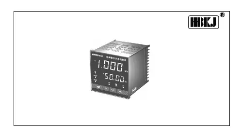
RB603系列智能恒压供水控制器使用说明书中国专利产品广州市百福电气设备有限公司V1.4.3目录Ⅰ前言 (I)Ⅱ安全注意事项 (II)一、产品特性 (1)1.1控制器的功能特性 (1)1.2型号说明 (1)1.3智能恒压供水控制器系列机型 (1)1.4检查要点 (2)二、外型尺寸 (3)2.1B603外形尺寸 (3)2.2B603B外形尺寸 (4)三、使用环境 (4)四、接线 (5)4.1主回路端子接线总览 (5)4.2控制端子功能接线总览 (5)4.3主回路的连接 (6)五、操作 (7)5.1操作面板 (7)5.2操作流程 (7)5.2.1上电初始化 (7)5.2.2参数设置 (7)六、功能参数 (8)七、应用指导 (15)7.1单泵供水接线与设置 (15)7.1.1系统及接线 (15)7.1.2系统调试流程 (15)7.1.3相关参数设置 (16)7.2双泵以上联动接线与设置 (16)7.2.1系统典型连接方式 (16)7.2.2相关参数设置 (17)7.3分时段供水应用设置 (18)7.3.1系统连接图 (18)7.3.2典型应用 (18)7.3.3相关参数设置 (19)7.4手/自动控制接线与参数设置 (19)7.4.1系统连接 (19)7.4.2相关应用及操作 (20)7.4.3相关参数设置 (20)7.5端子升降速控制供水应用例 (20)7.5.1电接点压力表控制系统接线 (20)7.5.2电接点压力表的调整 (20)7.5.3相关参数设置 (21)7.6抽水控制应用例 (21)7.6.1系统连接图 (21)7.6.2抽水应用 (21)7.6.3相关参数设置 (22)7.7应用小结 (22)八、故障信息与排除方法 (23)8.1水泵运转时的供水故障 (23)8.2控制器运行故障 (24)Ⅰ前言感谢您选用我公司B603系列智能恒压供水控制产品,我们将为您提供热情而周到的服务。
B603系列产品是专门为水泵设计配套的一体化智能控制器,B603智能控制器具有优越的性能和丰富的使用功能,能够满足各种场合的给排水控制,改善供水系统的品质,符合国家“节能、节水、节地、节材、环保”的新技术产品的要求。
User ManualAquaControl +Rainwater System ControllerItem no.: 351027Otto Graf GmbH Carl-Zeiss-Str. 2-6 Tel .: +49(0)7641-5890 Kunststofferzeugnisse D-79 331 Teningen Fax: +49(0)7641-58950Figure 1: View of equipment1:LED for power supply2:Information Display3:LED for drinking water operation4:LED for faults and malfunction5:Operating buttons6:Lower cover of the System Control7:The main fuse for the rainwater system controller is under thiscover.Figure 2: Sensor assembly12:Data cable13:Wire seal 314:Connection of the data cable is polarity protected.15:connect white wire here16:connect red wire here17:data cable terminal18:Wire seal 219:Wire seal 120:active measuring length21:When assembling be sure that the cable spacers are equally dis-tributed over the cable length.22:Stainless steel probe23:Tank floor24:Screws must be blunted ! (danger of injury)25:overflow26:Tank or riser wall27:Sensor28:Sensor control boxImportant notes on safety:Please read and follow safety instructions carefully before assembly or using the device!Equipment using a 120 V ~ supply may only be installed and commissioned by a qualified tradesman. The assembly place must allow all possible safety precautions when laying the attached cables.Power supply cables and data cables mast not be damaged or pinched in any way. Plan the assembly place so that you can reach the transformer easily and unplug it from the electrical outlet in dangerous situations.Choose the assembly place so that children cannot play or be near the device and its connections without supervision.Before opening the device, disconnect it from the main supply (unplug) otherwise there is a serious danger of an electrical shock.Fuses may only be replaced with standard-compliant parts with the same nominal value.All liability is excluded for damages which result from non-compliance of these in-structions or from improper handling of the device. At chosen intervals in this hand book we will give directions for safety precautions. These safety precautions have been specially marked:1. DescriptionThe AquaControl+ is an electronic water management control system.It has been developed especially for rainwater usage systems. It can be used with a wide variety of tank systems.Tanks made from metal or steel reinforced cement may only be used when the fol-lowing conditions have been correctly followed.Metal tanks lead to faulty readings. It is optimal to install the device so that the sensor is as far as possible from the metal sides so, for example, in the center of a cylindrical tank. The system controls offer an easy to use guide for the switch pro-gramming. Using an LCD display the fill measurement is shown in 1 % stages (in relation to the height of the tank).The sensor operates with 12 volts DC, supplied from the main control unit.All programmed values such as the tank height are retained after disconnection of the power supply or after loss of power.Performance features:–Fill level measurement display in 1% steps with a bar type indicator–Freely variable switching points in 1% steps for drinking water refill–Automatic flushing of the system intervals in days, and duration in minutes are programmable–Dialogue oriented user guidance (choice of language)–Equipment indication using 3 additional LED–Supervision of the sensor control box and the sensor–Error indications in simple text–Analog output for connection to external systems: 0-10V DC Technical data:Control electronics Measurement sensorsOperating current :24VAC Measurement voltage :12V DC Fused:T500mA Measuring frequency :(0.2-20)kHz Power consumption :3VA Data cable length :165 feet,maximum Tank height :9.8 feet (optional 20feet)Measurements :6.1”x6.5”x3.5”Measurements :3.6”x3.2”x2”Terminal 1Terminal 2-4Operating voltage : 24V AC Operating voltage : 24V AC Maximum Current: 5Amps Maximum Current: 1Amps Terminal 5Operating voltage : 120V AC/DCMaximum Current: 3AmpsAnalogue outlet:Minimal apparent ohmic resistance : 20K OhmShort circuit protection : YesShort circuit current : Approx 15mACable length : 650 feet, maximum ; shieldedNote:Only the control electronics in the device are protected by the fuse. Valves and pump connections are not protected. These are protected only by the mains supply via the circuit breaker.The yellow LED indicating “Drinking water operation”[3] is lit as soon as the valve switches over to the mains supply. The user is made aware that the system now uses water from the mains supply. The red LED for “Faults and malfunctions” [4] is lit as soon as the system identifies a fault. The display will then show a warning that describes the cause of the fault in plain text.2. Assembly2.1 Control systemThe mains plug of the transformer serves as an on / off switch.–Loosen the fastening screws of the lower cover [6] and remove the cover–Mark out drilling points and drill according to sketch–Fasten the device with the enclosed installation hardware (screw anchor and screws)Figure 3: Drilling outline for housing outline2 .2 Connection sensors and data cable:The sensor electronics comprise of a stainless steel probe [22] with red and white connecting wires [27] and the sensor control box [28].Figure 4: Sensor technology1.Now the sensor control box [28] (cover removed) should be installed onthe tank wall (preferably in the man hole shaft of the Graf synthetic tank).The location of the mounted sensor control box should be between 4” and6” above the overflow [25]. The enclosed screws should be used to securethe device. After fully tightening the screws, the points that are showingthemselves on the outside of the tank must be blunted to avoid injury [24].2.Measure the height from the bottom of the tank [23] to the end of theterminals [15] and [16] on the [28].3.Shorten the connection cable to suit the measured height.4.After shortening the cable, the distance between the cable fasteningspacers [21] should be set equally along the entire length. The cablefastening spacers prevent the red and white wires of the sensor fromcrossing over and thereby causing a slight distortion of the measurementreadings. If for any reason the cable fastening spacers cannot be mounted,an additional distortion of the measurement reading of approximately 1%may result.5.Connect the sensor cable to the sensor as described in the followinginstructions: Remove approximately 1/4" of insulation from both of thewires. Next, pass the red wire through the wire seal 1[19] and tighten thislightly, then connect the red wire to the terminal [16]. The free white wireis now passed through the wire seal 2 [18] and tightened lightly, thenconnect the white wire to the terminal [15].6.Now pass the end of the data cable [12] through the wire seal 3 [13].Lightly tighten the wire seal and connect the cable wire cores of the datacable [12] to the double terminal [14]. The connection of the data cable isreverse polarity protected. Attention! The screws should be tightenedwith care to ensure that they are not damaged through overtightening.7.Now recheck that all the connections and the sensor components havebeen fitted correctly. Replace the cover of the sensor control box andsecure this with the appropriate fastening screws.8.At the main system control unit,remove the jacket from the ends of thesensor data cables, strip about ¼'' of insulation from the wires, and inserteach wire into the appropriate terminal . Tighten the terminal screwssecurely.Figure 5: Connection of the sensor system at the System ControlNote:The red and the white wires going down to the probe should be straight and smooth to be drawn taught by the weight of the stainless steel probe. The stainless steel probe must hang just above the tank floor. When setting the spacers please be sure to distribute them equally over the complete length as shown in Figure 2.2.3. Electrical wiring diagramThe AquaControl+ offers the rain water system a dry run protection for the pump or the house water system when equipped with an external pump relay. In order for the dry run protection will function properly the rain water system must be wired according to the following diagram.Fuse 500mA1: Terminal 1G: Ground (grounding conductor)2: Terminal 224V/60Hz: Input 24V/AC3: Terminal 3P: Input 24V/AC4: Terminal 4NO,COM,NC: Terminal 5For the supply of 24V AC to operate valves and other accessories, external power must be supplied to the 24V AC input terminals using a transformer sufficient for the needs of the attached devices.Figure 6: electrical wiring diagram3 . Activation and calibration processBefore the energizing the equipment, be sure that all electrical connections are cor-rectly insulated and all covers are properly closed.Now open the transparent cover of the system controls. Plug the transformer into the outlet (this outlet must be exclusively for the equipment and be on its own breaker). The system runs a self-test automatically.For the duration of the system check (approx. 10 seconds) the following signal will be displayed in the window:Figure 7: Display during the equipment checkThe equipment type is shown on the first line and the software check in progress is shown in the second line.If after the initial installation check all is correct, the LCD indicator will display the fill level (in %).Figure 8 shows the LCD-display in the operation mode. The display shows the filling level and the operating modes as abbreviations: "FV" and "P". These abbre-viations correspond as follows:–FV+ :filter cleaning valve opened –FV- :filter cleaning valve closed–P+ :(pump on) house waterworks in operation –P- :(pump off) no water currently being withdrawnFigure 8: Display in the operation mode4. Set up of the system control:After putting into operation, the system control must be adjusted and programmed according to the conditions and requirements of the individual user's system. The required settings are easily programmed. There are four buttons for this purpose. All necessary programming data entries follow a menu displayed by the LCD. For the set up, follow all the points listed in table 1 in the sequence shown. Should any error in the sequence occur then it is necessary to begin the set up again from the beginning starting with the tank height. Begin the programming of the settings by pressing the button marked “MENU”.With the buttons “+” or “-” the menu may be scrolled backwards and forwards. With the respective menu point shown the values may be altered. For this the button “ENTER” must be used. The value begins to flash. With the “+” or “-” the desired value may now be entered according to individual requirements. When the desired value has been entered this must be confirmed by pressing the “ENTER” button. The value is only then taken over and stored in the programming of the unit. Through pressing the “MENU” button again the display changes back to the operation mode.It is possible to reset the unit to the factory setting standard values at any time. The resetting can only be carried out in the operation mode (Display see Figure 7): To do this press the “ENTER” button and hold it pressed. Now simultaneously in addition press the “MENU” button. After a short wait the following display will be shown:Figure 9: Message reset to standard factory settingsAs soon as this message is displayed the buttons may be releasedThe menu structure integrated in the system control is outlined in Figure 9. To bring up the menu, press and hold the …MENU“ button for longer than 5 seconds. All outputs are inactive when the menu level has been activated and operation of the device is suspended. The system automatically returns to operating mode when no entries have been received for approximately 30 seconds.key …MENU“ (>5s)Figure 10: Main menu levelPress the “ENTER” button to arrive at each of the listed sub-menu functions.Through pressing the “MENU” button again the display changes back to the opera-tion mode.Pump OFF (The numerical value is always smaller than with PUMP ON.)Pump ON (The numerical value is always smaller than with BACKUP ON.)Supply with municipal drinking water - OFFSupply with municipal drinking water - ON (The numerical value is always smaller than with BACKUP OFF.)Flush the drinking water supply piping every 14 days. The value “0“ switches the flushing off.Main menu levelFlush the drinking water supply pipes for 30 seconds.Cleaning the rainwater filter every 14 days The value 0 switches the cleaning process off. Cleaning the rainwater filter for 5 seconds Cleaning the rainwater filter when the fill level has increased by 2% after rainfall. If the fill level continues to increase, the rinsing will be repeated every 3 hours.Cleaning the drain tank every “x” days. Cleaning the drain tank for “x” minutes.This enables water to be pumped out of the main tank. The chosen numeric value “Transfer from” should always be greater than the numericvalue “BACKUP OFF”!The water will be pumped off when it rises above the set value. To prevent constant switching on and off of this function, it is pumped off to 2% under the opposed value.Numeric value is always greater than the value “BACKUP ON” and less than the value for “REFILL OFF”.Figure 11: Sub-menu “Switching points”Press the “ENTER“ button to alter the respective switching points The value to be altered will begin to blink. The value may then be adjusted by using the “+“ and the “-“ buttons. Press the “ENTER” button again when the displayed value should be accepted.The following is an introduction to the general device settings:(A 20 feet Sensor may be ordered.)Main menu levelNumeric value is always greater than the value for “REFILL ON”.Output 1 has been configured for the "Refill"function and NO = normally open. Therefore the valve (or the pump) for the function "Refill" should be attached at terminal 1.Output 2 has been configured for the "Backup" function and NC = normally closed.Figure 12: Sub-menu “General device description”For each terminal the selection between the following functions exists:BOOSTER PUMP NO BOOSTER PUMP NC CLEANER NO CLEANER NC BACKUP NO BACKUP NC TRANSFER NO TRANSFER NC REFILL NO REFILL NC PUMP NO PUMP NC DRAIN NO DRAIN NCNote:Please configure each output according the requirements of your rainwater system requirements.Output 3 has been configured for the "Pump" function and NO= normally open.Output 4 has been configured for the "Drain" function and NO= normally open.Output 5 has been configured for the "Error" function and NC= normally closed.The function of the output can be specified for each terminal separately (normally open or normally closed). Please consider the maximum current values for each in-dividual terminal:Terminal 1:5Amps Terminal 2:1Amps Terminal 3:1Amps Terminal 4:1Amps Terminal 5:3AmpsFigure 13: Allocation of the relay outputsNO : normally open COM : commonNC: normally closedThe last part of the operation level covers the manual functions:Figure 14: Sub-menu “Manual functions”Time scale in days; elapsed since the last flush using municipal drinking waterTime scale in days; elapsed since the last filter rinse.Activation of the filter rinse. The RINSE valve remains permanently switched on until reprogrammed to original setting.Main menu levelActivation of the flushing process for the municipal drinking water inlet pipe. The switch-over valve remains permanently switched on until reprogrammed to original setting.Activation of the drain tank cleaning. The DRAIN TANK valve remains permanently switched on until reprogrammed to original setting.The refill function may also be regulated by hand.The REFILL valve remains permanently switched on until reprogrammed to original setting.5. Error messages and fault correction:The operation of the system control should be checked at regular intervals (at least every 4 weeks).The error messages provide an indication of general symptoms. Additionaltroubleshooting will be required to determine the underlying cause and necessary actions.Please also take note that the system control device cannot sense any malfunc-tion of the municipal water supply or house water system. (No malfunction signal is supplied by external water supplies or devices to the system control device).If faults are recognized by the tank level sensor, the system control cannot continue to work properly.The following faults are shown in the plain text on the display:The reason for this error is that the whitesensor wire has been damaged.Error possibilities:-The data cable of the sensor control box is not connected to the data cable terminal [14] but has been connected to the sensor terminal- Wires of the data cable have been damagedThe sensor control box delivers no signaland must be replaced.For further diagnosis, remove the stainless steel weight [22] out of the water. If the error indication has now stopped, then the sensor itself was the cause of the fault. If the error indication continues, this implies that the sensor control box is defective.Figure 15: Error messagesIf the device shows no function at all then check whether the main electrical supply provides current and also check the house breakers.If the electrical outlet is working properly, then unplug the transformer from the system control. Once the system has been de-energized open the lower cover of the system control (see Figure 1) and check the rainwater system controller main fuse.6. Analog outlet:-Your device has been fitted with an analogue terminal. This terminal shows the per-cent values from the system control (0% -100%) by a voltage range from 0V to 10V DC. The following connection values apply:Minimal apparent ohmic resistance : 20K Ohm Short circuit protection : YesShort circuit current : Approx 15mACable length: 650 feet, maximum; shieldedThe communication between the system control to the sensor control box isinterrupted.First try re-setting the system control to the factory default settings . If the error message continues to be displayed then it is necessary to contact your service partner.Note: After resetting to the factorydefault settings all the newly programmed setting values will have been overwritten and must be re-programmed!Note:The system control is only capable of displaying whole percent values (no frac-tions). These are shown on the analogue signal display.Figure 16: Allocation of the analogue terminalAttachment A – Symbols used:Attention! Pull out the mains plug from the socket beforeopening the device.Attention! An error has occurred.Mains drinking water operationPage downPage upOnly for use in a dry areas.Room for your notes:Purchase date: ...................................Device serial number / Type: AS AQ RH.................Tank height: ...................................Software level AQ+ REV: U2.0Design and specifications are subject to change without notice Dated: September 2011 ; Version: AQ+ U2.0。
水箱自动补水控制器的操作指南说明书操作指南说明书为您提供水箱自动补水控制器的正确使用方法,以确保设备正常工作,满足您的需求。
一、简介水箱自动补水控制器是一种智能化的设备,具有自动控制水位、保护电机等核心功能。
它广泛应用于公共建筑、住宅小区和企业工厂等场所,可以方便地维护水箱的水位。
二、安装在安装前,请确保有关法规和安全标准的符合性已得到了认可。
确保使用地点的电源适配器与本装置的输入功率参数相一致。
1.在安装过程中,请勿使设备与水接触或弄湿,以免造成短路。
2.将控制器直接固定在水箱控制箱上,并将相应的阀门连接到水管上。
3.安装完毕后,请检查安装是否牢固,以免设备在工作过程中出现松动或者故障。
三、使用1.开启电源,设备进入工作状态。
2.设备可以手动和自动工作模式切换,如需手动模式,请按一下设备上的“手动”按键;如需自动模式,请按一下设备上的“自动”按键。
3.为了保障水位的稳定,您可以根据实际需要在设备上设置水位高度。
找到“设定”按键并按下,随后调节上下方向键可以设置出水量的大小。
4.如果您需要停止补水,请按下设备上的“停止”按键。
四、预防措施1.请勿将设备安装在高温、潮湿和多尘的环境中,以免引起系统故障。
2.请勿随意拆卸或者改装设备,以免影响系统的稳定性和安全性。
3.请勿在水箱内倒入腐蚀性或者易爆性的液体,以免对设备造成损坏。
另外,如果在使用过程中发现设备发生故障,请第一时间联系设备售后服务中心或者厂家,同时注意设备的日常维护和保养。
五、总结以上就是水箱自动补水控制器的操作指南说明书,仅供参考,希望能够对您的使用有所帮助。
如果您有任何疑问,请联系售后服务中心或者厂家。
节水控制器使用说明书水控机使用说明书一:节水控制器接线方式:1.电源线:红黑为电源线,红正黑负,对应接12V直流电源的正负极。
2.阀线:蓝紫为阀线,蓝正紫负,蓝线接阀的红线,紫线接阀的黑线。
3.通讯线:棕黄为通讯线,棕正黄负,对应接485的正(+)负(-)。
图示如下:红黑蓝紫棕黄+ —红黑+ —二.节水控制器上电启动显示如下:1.显示:引导6664,表示支持485在线下载。
2.显示:产品品名。
例如:IDL2表示ID水控器;-tSC表示一卡通水控器。
3.显示:板子型号。
例如:668,表示6.68板子。
4.显示:"TEST",如果存储器正常,该内容一闪而过,如果存储器不能正常工作,"TEST"会停留在屏幕上。
5.显示:开阀因子和关阀因子6.显示:控制器工作模式字A B C D- 1 -其中:A:计费方式:0-计时方式,1-计量方式。
B:阀门控制方式:0-TTL,1-1#继电器,2-2#继电器,3-双继电器C:阀门种类:0-双稳态,1-单稳态。
D:连网方式:0-联网,1-脱网7.阀门自检,自动打开关闭一次。
8.显示程序版本号: A B C D 。
例如:8A30,表示程序版本号为8A30。
9.显示:波特率:960010.显示:机器设备号(站点号)。
三:配套软件配置:1:一卡通水控器使用6.68软件,ID水控器使用1.88或1.98软件。
2:在软件中设置用水费率,控制器工作模式等各个参数。
3:用水费率:针对用水量的多少而收取相应费用的计费标准就是费率,具体表示形式如下:计时费率:分钱/秒,例如1分钱/6秒,每6秒钟扣除1分钱.四.节水控制器刷卡方式1:一卡通计时(计量)水控器:采用放卡出水,拔卡停水的控制方式。
例如:费率设为3秒2分钱,仅仅刷卡开阀,则消费完1.2元后自动关阀。
五.一整套配置:1:电机阀组建1套。
2:节水控制器一台。
3:外电源线,和外通讯线各一套。
4:M3*30木螺钉4只,塑料膨胀塞4只。
- - -. - - 总结资料 水 控 系 统 软 件 (版本:150)
使 用 说 明 书 - - -.
- - 总结资料 1 系统简介 本系统采用先进的感应式IC卡技术和多功能水控机,利用电脑强大的数据处理功能,以及数据库管理技术,使收费管理现代化,从而实现:
灵活多变的收费方式 根据客户的要求可以随时设置扣款方式。 操作简单,准确快捷的电子交易,使持卡用户更方便 强大的数据查询功能和分析报表 提高收费的管理水平和运作效率 系统软件为Windows图形界面,直观易学,操作简便
2 系统构成 2.1 运作流程 *随系统配置而定
2.2 系统组成 2.2.1 硬件 硬件组成: 微机:P800 / 256M / 彩显 / 20G(2个) / PS2鼠标1台(最低配置) (&.系统数据采用双硬盘备份 ) 感应式发卡机(RD_1) 1台
消费 系统安装 设置系统参数 发用户卡 管理人员 持卡用户 存取款
发设置卡
退卡 查询统计报表 定期备份数据 - - -.
- - 总结资料 感应式水控 定购量 感应式IC卡 定购量
2.2.2 软件 单机版 Window95/98/2000/xp 水控软件150
3 系统安装
3.1 硬件安装 发卡机的安装 连接发卡机的通讯电缆一端在发卡机通讯接口,另一端至计算机的通讯端口1或N和USB口
3.2 软件安装 运行安装盘的“充值软件_1_0_0_150.exe”,按默认的安装就行了。 3.3 第一次使用
软硬件安装调试完成后,会把该软件的快捷方式放在桌面上,名字叫“充值系统” ,双击图标就可以启动(第一次启动如下图) - - -.
- - 总结资料 这是正式使用系统的一些参数设置: 一.设备参数 1) 读写器端口扫描X围,就是发卡机和电脑连接的端口,如是用电脑的串口1,则是从1到1(一般如果是USB读写器是安装好后一般是3口(可以到电脑里的设置里看一下安装好的端口是那个)这里就填3到3)(必填) 2) 终端机端口扫描X围(备用) 3) 单位名称:就是定义自己单位的名字。(可填或不填) 4) 单位代码:是自己单位定义的代码(这是为了区别单位和单位之间的不同,必须是四位数)(必填,发过卡片之后就不能在更改!) 5) 卡片密码定义:这里选择“通用XX码”(到系统安装完所在的目录,修改sysprm.ini文件中的cardpsw=00AE16EC11D5 附:卡号X围,消费费率,定餐信息(这三个备用)。 二.消费费率: - - -.
- - 总结资料 单位转换 是1元=100升 三.制功能卡:
选择功能卡类型有如下几种: - - -.
- - 总结资料 1) 时间设置卡(用于计量限量水控下传时间到IC卡节水器) 2)初始化卡(把水控软件里面的参数写入到卡上,每台水控机都是读一下初始化机才可以使用所发的卡片,使用时把初始化卡片放在水控机上感应区,会出现信息,完成后自动返回(注意:此卡是把系统设置的单位代码下传到IC卡节水器) 3)清除卡(把水控机里面的数据清除,使用里把清除卡放在水控机感应器会出现清除的信息,清除完后水控机自动返回)
4)费率卡(‘信息提示’上面的信息就是设置“费率卡”的参数. 费率卡设置说明:费率1(单位:分)设置成1,扣钱单位(秒/升)是2,代表是1分钱出1升水,费率2(单位:分)设成2代表是一天可以使用4分钱, 扣钱单位(秒/升)设置成2代表是一天可以使用2次.( 费率2(单位:分)和费率2下的扣钱单位(秒/升)是水控机一天有限量的情况才会使用到,一般情况不用设置)
举例说明: (1)计量使用 0.3元每桶热水的收费标准,(每桶水按20升/桶计算)设置如下: 把收费标准换算成“元/升”,即0.3元÷20升=0.0015元/升; 水控的收费精确度为分,不能精确到厘,则要把1.5分换算成最小整数,1.5分×2=3分,表示每2升水扣3分钱。则把“费率1(单位:分)”设置成“003”就可以了,“扣钱单位(秒/升)”设置成“004”表示4个脉冲2升水。“费率2(单位:分)”设置成“200”,“扣钱单位(秒/升)”设置成“200”,费率设置成功后,点击“确定写卡”费率卡就设置成功。如果0.4元/桶,则0.4元÷20升=0.002元/升,则把“费率1(单位:分)”设置成“002”,“扣钱单位(秒/升)”设置成“002”,“费率2(单位:分)”和“扣钱单位(秒/升)”不变。 (2)计量限量使用 0.3元每桶热水的收费标准,(每桶水按20升/桶计算),每天每X卡限量使用20升热水,设置如下: 把收费标准换算成“元/升”,即0.3元÷20升=0.0015元/升: - - -. - - 总结资料 水控的收费精确度为分,不能精确到厘,则要把1.5分换算成最小整数,1.5分×2=3分,表示每2升水扣3分钱。则把“费率1(单位:分)”设置成“003”就可以了,“扣钱单位(秒/升)”设置成“004”表示4个脉冲2升水。“费率2(单位:分)”设置成“030”,“扣钱单位(秒/升)”设置成“050”,费率设置成功后会“嘀”的一声报警,失败会报警(E----16)。如果0.4元/桶,则0.4元÷20升=0.002元/升,则把“费率1(单位:分)”设置成“002”,“扣钱单位(秒/升)”设置成“002”,“费率2(单位:分)”设置成“040”和“扣钱单位(秒/升)”设置成“050”,表示每1升水扣2分钱。 注:“费率2(单位:分)”中“030”表示每天限量使用的“钱”,每X用完0.3元(即20升水)后当天此卡将不能再使用了,必须相隔24小时后才能再使用。 “扣钱单位(秒/升)”表示此X卡每天能使用的次数,“050”表示此X卡每天能使用50次。
注:一体流量热水水控中的“扣钱单位(秒/升)”的脉冲数中,2个脉冲表示为1升水。
5)早上,中午,下午,晚上是限制使用的量:这里设置单位是升(备用) 把这些卡放在水控机器上的技巧:把制作功能卡放在水控机的标有感应说明的地方2秒就行了。 附:选中上面卡的类型后放卡,再点击“确定写卡”就可以完成需要的卡类型
三.权限设置: - - -.
- - 总结资料 这是设置权限,客户可能自己自行设置需要那些权限(但建议全选上,以后熟悉了再更改权限),把“操作员”,“操作编号”,“操作密码”,都填好,会出现“新增保存”,点“新增保存”就行了。
四.登录界面:
系统默认的操作号‘8888’和密码‘8888’点“确定”就可以进入本系统。 - - -.
- - 总结资料 3.4 主界面
3.5 操作 3.5.1 参数设置: 1) 参数设置(上面已详细讲解,参考上面设置)。 2) 权限设置(上面已详细讲解,参考上面设置)。 3) 切换用户(不用退出软件而可以直接用其它的用户名登录)。
3.5.2 报表管理 1)现金报表 - - -. - - 总结资料 这是一份详细的存取款情况,可以根据情况打印所需要的报表。 2)消费报表(备用)。 - - -.
- - 总结资料 3.5.3 卡片管理
用鼠标右键单击“自定义部门”会出现在“增加子层部门”,“删除选中部门”,“修改部六名称”, “保存所有修改”。可以根据自己的情况定义好。 增加子层部门时,会出现如下图: - - -.
- - 总结资料 部门编号可以使用默认的,在部门名称填入信息点确定就行了。 1) 点“新增人员”后出现如下:
手工追加是软件自动增加人事资料,本软件可以自动导入人事资料进行发卡(导入人事资料方法光盘里有详细说明),后点“确定“确认刚才所做的操作。
2) 删除人员(选择上面的人员后可以删除)。 3) 发行新卡(下图所示) - - -.
- - 总结资料 先选中所要发卡的人员,点发行新卡,就会出现发行新卡的画面,根据情况输入“卡押金“, “工本费“,”收现金“,把卡片放在读写器上,点”开始发行“后上面如显示发卡成功就代表该卡发行成功。 处理情况会出现信息,如成功会显示入库成功,说明该卡已发成功,如报“该卡已发行,请更换新卡”就说明该卡里面已写了信息,如想把这X重新使用,则要用到“系统维护”中的“清整卡片”做了这一步清卡后该卡才可以重新发行。
4)挂失解挂(备用)。 5)补发新卡:先选中要补发新卡的人员再点“补发新卡”,会出现如下的画面: 附:为了减轻发卡工作量和快速发行新卡,可以使用批量发卡功能,方法如下: 选中第一个要发行的人员,按键盘的“SHIFT”键,再按键盘的“↓”键,这时就可以选中很多人员(建议一次性发卡不要超300人,发完300人后再发下一个人员),后再点下面的“发行新卡”就会把这些所选的人员添加到即将发卡的屏幕上。点“开始发行”就可以,发完一X,再放另一X新卡,这时会自动发第二X,。。。。。