VORILS教程
- 格式:docx
- 大小:37.27 KB
- 文档页数:2

VOICELIVE TOUCH PARAMETER REFERENCE CHART V1.0MIX LEVELS1.VoicesOff to +6dB2.Delay/ReverbOff to +6dB3.GuitarOff to +24dB4.Guitar EffectsOff to 0dB5.Aux InOff to 0dBB InOff to 0dBSETUP MENU1.Phantom PowerOff,On2.T one Style:Off1 Normal2 Less Bright3 Normal + Warmth4 More Compression5 Normal No Gate6 Less Bright No Gate7 Warmth No Gate8 More Comp No Gate3.Pitch Correct Amount 0-100%4.Guitar FX Style:Off1 Thicken + Hall2 Hall3 Thicken + Room4 Room5 Thicken + Arena6 Arena7 Thicken5.OutputStereoMonoBStereoTrackInsert7.T ap GlobalOff,On8.Key & Scale Global Off,On 9.NaturalPlay GlobalOffAutoGuitarMIDIAuxScaleShiftNotesNotes 4 Channel10.Pedal1 Harm Favorite Loop2 Loop Stop Undo3 Loop Left Right (arrows)4 Talk Bank Favorite5 Harm Bank Favorite6 Harm Preset10s Preset1s7 Talk Preset10s Preset1s8 Harm Stop Loop11.MIDI Channel1-16MIDI MENU1.MIDI Channel2.FilterNoneProgram ChangeSystem ExclusivePrg Change + Sysex Channel4.T ranspose+/- 4 Octaves5.Keyboard SplitAboveBelow6.Keyboard Split NoteC-1 to G97.Sysex ID #0-126,Any8.Vibrato Wheel BoostBoost,Manual9.Pitch Bend Range0-12 Semitones10.MIDI ControlMergeMIDIUSBDELAY MENU1.LevelOff to 0dB2.Style0 Quarter1 Eight2 Triplet3 Dotted4 Long Dot5 Long Trip6 Sixteenth7 Ping Pong 18 Ping Pong 29 Ping Pong 310 Multi Tap 111 Multi Tap 212 Multi Tap 313 Multi Tap 414 Multi Tap 515 Multi Tap 616 Classic Slap17 Single Slap3.Lead LevelOff to 0dB4.Width0 to 100%REVERB MENU1.LevelOff to 0dB2.Style0 Smooth Plate1 Soft Hall2 Amsterdam Hall3 Broadway Hall4 Snappy Room5 Library6 Dark Room7 Music Club8 Studio Live Room9 Stretched Room10 Warehouse11 Bouncy Room12 Real Plate13 Reflection Plate14 Thin Plate15 Bright Chamber16 Bright Plate17 Real Plate Short18 Real Plate Long19 Wooden Chamber20 Jazz PlateADVANCED MENU1.Scroll Speed10(fastest) to 50(slowest)2.Lead MuteOff,On3.Lead DelayNone,Voices4.Guitar MuteOff,On5.Loop UndoOff,On6.Loop Feedback0-100%7.Output LevelOff to 0dB8.T uning Reference420 to 460 Hz9.Demo ModeOff,OnµMOD MENU1.LevelOff to 0dB2.Style0 Micromod Clone1 Micromod wider2 Thicken3 Light Chorus4 Medium Chorus5 Wide Chorus6 Mono Chorus7 Fast Rotor8 Flanger9 Flange Feedback10 Flange Negative11 Mono Flange12 Soft Flange13 Panner14 Tube15 Up Tube16 Down Tube17 Down & Up Tube18 Rise & Fall19 Ottowa Wide20 Cylon Mono21 Cylon Stereo22 Alien Voiceover23 Underwater3.Lead LevelOff to 0dB21 Quick Plate22 St Joseph Church23 Hockey Arena24 Dome Chapel25 Museum26 Indoor Arena27 Cozy Corner28 Thin Spring29 Full Spring3.Lead LevelOff to 0dBFX MENU1.HardT une StyleOff1 Hard Tune2 Female Gender3 Male Gender4 Octave Up5 Octave Down6 Female Octave Up7 Male Octave Down8 Male Octave Up9 Fem Octave Down10 Natural11 Natural Female Gender12 Natural male Gender 2.T ransducer Style1 Lowcut 12 Lowcut 23 Bandpass 14 Bandpass 25 Highcut6 Midcut7 Soft Drive8 Medium Drive9 Hard Drive10 Radio11 Radio Drive12 Peak Radio13 Boxey Radio14 Clear Megaphone15 Clip Megaphone16 Beat Box3.Low Cut Frequency 85 Hz to 20kHz4.T ransducer Level-20dB to +20dB5.T ransducer Routing OffLeadHarmony + Double VoicesLead FXHarmony FX DOUBLE MENU1.LevelOff to 0db2.Style0 Voice Tight1 Voice Loose2 Voices Wide3 Voices Tight4 Voices Wide5 Voices Mono3.Lead LevelOff to 0dBHARMONY MENU1.LevelOff to 0dB2.Style0 1 Voice Above ( High)1 1 Voice Below ( Low)2 1 Above 1 Below (Low+High)3 2 Voices Above (High+Higher)4 2 Voices Below ( Lower+Low)5 Far Above Far Below (Higher+Lower)6 2 Above 1 Below (Low+High+Higher)7 1 Above 2 Below (Lower+Low+High)8 2 Above Far Below (Lower+High+Higher)9 2 Above2 Below (Lower+Low+High+Higher)10 Gospel High (Low+High+Higher)11 Gospel Low (lower+Low+High)12 Upper Choir (High+Higher)13 Lower Choir ( Low+Lower)14 Bass Boys ( Low+Lower)3.DoubleOffOnChoirBoth4.Lead LevelOff to 0dB5.NaturalPlayAutoGuitarMIDIAuxScaleShiftNotesNotes 4 Channel6.KeyC to B7.ScaleM1(Major1),M2(Major 2),M3(Major 3)m1(Minor1),m1(Minor 2),m1(Minor 3)HARMONY VOICE MENUS1.LevelOff to 0dB2.PanLeft,99 to 0,Center,0 to 99,Right3.Gender-50(Male) to 50(Female)。
Virtools快速入门教程Virtools D ev设计制作步骤1. 组织资源2. 设计内容,就是你要做的cmo是干什么的3. 输入媒体,模型角色等4. 安排场景5. 为场景设计交互6. 测试场景7. 基于测试然后精炼场景8. 重复6-7的步骤直到场景符合要求9. 发布Virtools D ev设计制作步骤2这个教程包含的资源是VirtoolsResources,VirtoolsResources 在默认情况下是安装好的. 当然, 如果你没安装,你现在就可以选择安装,并且选择只安装VirtoolsResources资源。
要使用资源, 先要打开VirtoolsResources。
1. 选择Resources 菜单,选择Open Data Resource。
2. 在Virtools Dev程序目录下打开Documentation子目录。
选择VirtoolsResources.rsc 并点击Open。
28.3 Plan the Content通常,计划内容是你自己的责任,但这是一个快速入门教程,所以我们已经为你进行了所有的设计:你用已经准备好的模型创建一个世界,里面有一个可以控制的角色,和世界能进行碰撞,还有可以控制的不同的视点。
28.4 Import Media一旦你有了一个清晰地设计思路,下一步就是输入相应的资源。
28.4.1 Importing the SceneryVirtools Dev是一个创作平台, 擅长于整合媒体并加入交互。
媒体可以有多种类型::3D模型,3D角色模型及其动画,声音等。
通常,媒体是在其它的应用程序中被创造并输出的Virtools Dev可以解读的格式。
资源都是一些的嵌套的目录和文件。
下面我们就一步一步的迈入QUICK START1. 在VirtoolsResources资源菜单,选择Apartment.nmo(3D Entities/Worlds )檔拖曳到3D Layout 窗口并释放。


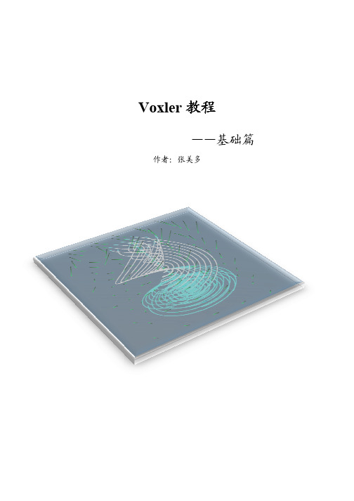
Voxler 教程——基础篇 基础篇作者:张美多简介: 简介:作者从事水利方面物探工作,在实际工作中,发现对于后期数据结果的空间展 示缺乏相应的软件支持,虽然通过文字描述、列表格、画剖面图等可以表达清楚物 性关系, 但对于非专业人员仍会造成困扰。
而 Voxler 这款软件恰恰能够解决这方面 的问题,通过实际应用,该软件对于异常体在三维空间展示有较好的表现效果。
与 此同时,除了在物探领域,在诸如地质、测量、医学和气象等其他领域,该软件也 能发挥非常好的作用。
此教程是 Voxler 系列教程中的基础篇,主要介绍 Voxler 软件的基础应用,通 过这篇教程,可以使初学者迅速掌握该软件的使用。
教程中结合实际数据配有许多 示意图,步骤清晰,方便读者跟随操作。
写作时使用的软件版本为最新的 Voxler3。
能力有限,文中难免错误之处,请不吝斧正,邮箱:zhangmeiduo@ 。
作者:张美多 2014 年 6 月 16 日 于天津目录前言 ...........................................................................................................................................1 1 数据导入 ................................................................................................................................2 2 创建输出图像模块 .................................................................................................................4 2.1 创建散点图 .................................................................................................................4 2.2 添加边界框 .................................................................................................................4 3 改变属性 ................................................................................................................................5 3.1 BoundingBox 属性 ........................................................................................................5 3.2 颜色属性 .....................................................................................................................6 3.3 显示标签 .....................................................................................................................9 4 使用计算模块...................................................................................................................... 10 4.1 数据网格化 ............................................................................................................... 11 4.2 创建等值面 ............................................................................................................... 11 4.3 改变 Isosurface 属性 ................................................................................................. 12 4.4 关于透明度要注意的问题 ........................................................................................ 14 4.5 数据滤波 ................................................................................................................... 14 5 多模块连接 ......................................................................................................................... 17 5.1 添加等值线 ................................................................................................................ 17 5.2 改变透明度 ................................................................................................................ 18 6 保存信息 ............................................................................................................................. 19 6.1 保存一个 Network .................................................................................................... 19 6.2 保存数据 ................................................................................................................... 19 6.3 保存图像 ................................................................................................................... 20 6.4 截屏 .......................................................................................................................... 20 6.5 录制视频 ................................................................................................................... 20 7 导入测井数据...................................................................................................................... 20 7.1 导入井口数据 ............................................................................................................ 20 7.2 导入轨迹数据 ........................................................................................................... 22 7.3 展示钻孔 ................................................................................................................... 23 后记 ......................................................................................................................................... 24Voxler 教程——基础篇前言Voxler 软件简介 软件简介: 简介: Voxler 软件是一款三维科学绘图工具软件, 主要用来展示三维体的透视关系和在空间中展 布三维数据点,同时也可展示二维数据等。

vroid使用方法VRoid is a free software that allows users to create 3D characters with ease. It is a popular tool among artists, designers, and content creators who want to bring their creations to life in the virtual world. Using VRoid is a fun and intuitive process that can be done by anyone, regardless of their level of experience in 3D modeling.VRoid使用方法非常简单易懂,即使你没有任何3D建模经验,也可以轻松上手。
首先,你需要去VRoid官网下载软件并安装到你的电脑上。
安装完成后,打开软件并创建新的项目。
在项目中,你可以选择不同的模板角色,或者从零开始创建你自己的角色。
One of the key features of VRoid is the ability to customize every aspect of your character, from their hairstyle to their facial expressions. You can choose from a wide range of pre-set options or even create your own unique designs. This level of customization allows users to truly make their characters their own and bring their creative vision to life.VRoid还提供了丰富的服装、配饰等选项,使你的角色更加个性化。
Quick start user manualSection 1The warnings in this manual must be observed together with the "USER MANUAL - Section 2".Le avvertenze nel presente manuale devono essere osservate congiuntamente al “MANUALE D’USO – Sezione 2”.Die Warnungen in diesem Handbuch müssen in Verbindung mit der "BEDIENUNGSANLEITUNG - Abschnitt 2" beobachtet werden”.Les avertissements specifiés dans ce manuel doivent être respectés ainsi que les "CARACTERISTIQUES TECHNIQUES -Section 2"Las advertencias del presente manual se deben tener en cuenta conjuntamente con las del “MANUAL DEL USUARIO” - Sección 2”.A.E.B. Industriale Srl Via Brodolini, 8 Località Crespellano 40053 VALSAMOGGIA BOLOGNA (ITALIA)Thank you for choosing a dBTechnologies Product!VIO S118 is an active horn loaded subwoofer, designed for professional use, easy to fly, equipped with one 18” woofer (voice coil: 4”). The powerful DIGIPRO® G4 amplifier section, capable of handling up to 1600 W (RMS power), is controlled by a DSP, which can perform a detailed customization of the output sound of the subwoofer. In particular, thanks to the complete control interface, it is possible to accurately tune various types of configurations, like cardioid or end-fire. The RDnet connections allow in-depth remote control, thanks also to free available software (dBTechnologies Network, dBTechnologies Composer). WPD (wireless position detection) is a new feature which allows recognizing the placement of the subwoofer in line-array (in the real use). Professional accessories (like FSA-VIOL210 flown adapter, GSA-VIOL210 stack adapter, DRK-210 fly-bar, DO-VIOS118 dolly) ensure easy set-up to create different configurations, completing live installations with VIO-L210 line-arrays.Check the site for the complete user manual!1) UnpackingThe box contains:No. VIO S118No. 1 Mains cable with Neutrik® powerCON TRUE1connectorNo. 1 FuseThis quick start and warranty documentation2) Easy installationThe quick assembly in line-array is guaranteed by:UPPER SIDEfront retractable brackets (A), for anchoring to ahigher subwoofer or DRK-210 fly-bar (flowninstallation)rear retractable brackets(B), for anchoring to ahigher subwoofer, to DRK-210 fly-bar (flowninstallation) or to GSA-VIOL210 (stacked installation)quick-release pins (C) for securing the retractablebracketsLOWER SIDEfront anchorage system(D), for anchoring to alower subwoofer or to VIO-L210 module (flowninstallation)rear anchorage system (E), for anchoring to alower subwoofer or to FSA-VIOL210 (flowninstallation)TOP AND LATERAL SIDESpick points forDRK- 210 fly-bar (F)(stacked mounting)pole-mount adapter (G)(M20 threaded hole)handles (H) (2 for eachside)The use of main accessories for each type ofinstallation is illustrated in the pictures below. Pleaserefer to the related instructions and complete manualsfor further information.The product and accessories must be handled bytrained personnel only! The user is required tofollow regulations and mandatory laws onsafety of the country in which the product is used. Don’tuse handles and/or roping points to suspend VIO S118!3) First switch-onThe DIGIPRO G4 amplifier of VIO S118 is controlled by a powerful DSP. All the connections and controls are in the rear amplifier control panel:The subwoofer is supplied with a mounted fuse for operation within the 220-240V~ range. If you need to operate in the 100-120V~ voltage range:▪ Disconnect all connections, including the powersupply▪ Wait 5 minutes▪ Replace the fuse with the one provided in thepackage for the 100-120V~ range1 – Input (balanced) connector2 – Link/Xover Out (balanced) connector3 – Subwoofer attenuation rotary control4 – Delay rotary controls5 – Polarity switch6 – Cardioid preset switch7 – Link/Xover Out switch8 – Xover LPF9 – Status LEDs (Limiter, Signal, Mute/Protection, Ready)10 – RDNet Data In 11 – RDNet Data Out 12 – RDNet status LEDs 13 – System test switch14 – USB Data Service (USB-standard Type B) 15 – Full Range Mains input connector 16 – Mains Link connector 17 – Mains Fusea) Once you have properly set up the desiredconfiguration (see also the VIO S118 complete user manual and accessories instructions for further information), connect the audio input (1). Set the Subwoofer attenuation (3) to 0 dB.b) Connect the possible output direct link (2), and set the Link/Xover Out switch (7). If your choice is Xover, you can choose the LPF frequency with (8) Xover rotary. This filter does not affect the “Link” output, if selected with (7).c) Choose the Subwoofer Setup (Delay 4, Polarity 5) In cardioid configuration, please note that thecardioid preset switch (6), when active, bypass these controls.d) In case of remote control, connect the Data Input (10) to the hardware remote controller (RDNetControl 2 or RDNet Control 8) with cables equipped with etherCON connectors. Then connect the Data Output (11) to the Data Input (10) of a possiblesecond device, and so on. When the RDNet network is on and it has recognized the connected device, the LED “Link” (12) is on. The other LEDs (12) “Active” start blinking at the presence of data transmission, the “Remote Preset Active” advise that all the local controls set on the amplifier panel (level, DSPpresets, etc.) are by-passed and controlled remotely by RDNet. In remote control it is essential the use of free dBTechnologies software:∙ dBTechnologies Network,useful for an in-depth control of different devices in remote connection;∙ dBTechnologies Composer,useful for the complete sound system design for various professional needs, particularly developed for VIO series.e) Connect the power supply (15). Link the power to other subwoofer or modules (see Technical Data for further information) using mains link connector (16).For further information, download the complete user manual and the free software:/EN/Downloads.aspx or scan the QR code.Technical DataSpeaker Type: Active horn-loaded subwooferAcoustical dataFrequency Response [-6 dB]:36 Hz – Cut frequency(crossover - dependent)Frequency Response [-10 dB (HPF)]:33 HzMax SPL (1 m): 139 dBLF: 1 x 18”LF Voice Coil: 4”Crossover freq.: 60 to 110 Hz + full-rangeDirectivity: (omnidirectional) Cardioid with DSPAmplifierAmp Technology: Digipro® G4Power supply: Full range with PFCAmp Class: Class-DRMS Power: 1600 WPeak Power: 3200 WCooling: Passive (convection)Operating voltage:100-240V~ 50-60 Hz (Full Range)Wireless position recognition: WPD technologyProcessorController: DSP, 64 bit 96 kHzLimiter: Peak, RMS, ThermalControls: Rotary Delay Control (0-9.9 ms, steps: 0.1 ms),switches (Link/Xover, Cardioid Preset, System test,Phase), Subwoofer level, Xover LPFInputMains connections: PowerCON® TRUE1 In/linkMaximum number of subwoofer for each daisy chainpower connection [mains input + mains link]: 1+3 VIOS118** (220-240V~), 1+1 VIO S118** (100-120V~)Signal Input: (Balanced)1x IN (female)Signal Out: (Balanced) Link OUT (male)RDNET connectors:Data In / Data OutUSB connector: standard USB B-type (for SERVICE DATA)MechanicsHousing: Wooden box/black polyurea finishGrille: Full metal (CNC machining)Handles: 2 per sideRigging points: 4 in the upper side, 4 in the lower sidePick points (stack mode): yes (on top for DRK210)Width: 720 mm (28.34 in)Height: 520 mm (20.47 in)Depth: 695 mm (27.36 in)Weight: 45.1 kg (99.42 lbs.)Download the complete user manual on:/EN/Downloads.aspxEMI CLASSIFICATIONAccording to the standards EN 55103 this equipment is designed and suitable to operate in E5 Electromagnetic environments.FCC CLASS A STATEMENT ACCORDING TO TITLE 47, PART 15, SUBPART B, §15.105This equipment has been tested and found to comply with the limits for a Class A digital device, pursuant to part 15 of the FCC Rules.These limits are designed to provide reasonable protection against harmful interference when the equipment is operated in a commercial environment.This equipment generates, uses and can radiate radio frequency energy and, if not installed and used in accordance with the instructions, may cause harmful interference to radio communications.Operation of this equipment in a residential area is likely to cause harmful interference in which case the user will be required to correct the interference at his own expense.Changes or modifications not expressly approved by the party responsible for compliance could void the user’s authority to operate the equipment.WARNING: This equipment is compliant with Class A of CISPR 32. In a residential environment this equipment may cause radio interference. WARNING: Make sure that the loudspeaker is securely installed in a stable position to avoid any injuries or damages to persons or properties. For safety reasons do not place one loudspeaker on top of another without proper fastening systems. Before hanging the loudspeaker check all the components for damages, deformations, missing or damaged parts that may compromise safety during installation. If you use the loudspeakers outdoor avoid spots exposed to bad weather conditions.Contact dB Technologies for accessories to be used with speakers. dBTechnologies will not accept any responsibility for damages caused by inappropriate accessories or additional devices.Features, specification and appearance of products are subject to change without notice.dBTechnologies reserves the right to make changes or improvements in design or manufacturing without assuming any obligation to change or improve products previously manufactured.Scan withyour QRReader App todownload thecomplete UserManual。
vonr volte流程Vonr VoLTE流程随着移动通信技术的发展,VoLTE(Voice over LTE)作为一种新兴的通信技术,逐渐受到了广大用户的关注。
Vonr(Voice over new radio)则是在5G网络中的VoLTE技术的具体实现方式。
本文将围绕Vonr VoLTE流程展开,详细介绍其运作原理和实施过程。
一、Vonr VoLTE的基本概念Vonr VoLTE是一种基于5G网络的语音通信技术,通过将语音数据转换为数据包,并通过IP网络进行传输,使语音通话能够与数据通信在同一个网络上进行。
相比传统的2G/3G通信技术,Vonr VoLTE具有更高的通话质量和更低的通话延迟,同时还可以提供高清语音、多方通话等增强功能。
二、Vonr VoLTE的实施过程1. 设备准备阶段在Vonr VoLTE实施前,需要确保用户的终端设备支持VoLTE功能。
终端设备需要具备VoLTE芯片,同时还需要进行相关的软件升级。
运营商也需要对自身的网络进行升级,以支持Vonr VoLTE的正常运行。
2. 注册阶段当终端设备接入支持Vonr VoLTE的网络后,会发送注册请求到运营商的IMS(IP Multimedia Subsystem)网络。
IMS网络对用户进行认证,并为用户分配一个唯一的SIP(Session Initiation Protocol)地址,用于后续的通信。
3. 通话建立阶段在通话建立阶段,用户通过终端设备发起呼叫请求。
终端设备将呼叫请求发送到运营商的IMS网络,IMS网络根据被叫用户的SIP地址找到对应的终端设备。
双方终端设备之间通过IMS网络建立起通话连接,语音数据通过IP网络传输。
4. 语音传输阶段在通话过程中,语音数据通过IP网络进行传输。
Vonr VoLTE采用IP多媒体子系统(IMS)架构,利用IP协议实现语音数据的传输。
通过在5G网络中使用更高的带宽,Vonr VoLTE可以提供更高质量的语音通话体验。
VIVADO下ILA使用指南ILA是VIVADO下的一个DEBUG- IP,类似于片上逻辑分析仪,通过在RTL设计中嵌入ILA核,可以抓取信号的实时波形,帮助我们定位问题。
本文档以一个简单的COUNTER设计为例,对VIVADO(2014.1)下ILA核的使用进行说明。
第一部分 RTL设计module counter(input clk,output [3:0] q);wire clk;//想抓取cnt信号进行观察(* keep = "TRUE" *)reg [3:0] cnt = 4'd0;assign q = cnt;always@(posedge clk)begincnt <= cnt + 4'd1;endendmodule第二部分加入LIA核在vivado工程中,打开IP Catalog选项,找到ILA核进入ILA核的配置界面(2页)第一页在“component Name”可以修改例化名, 在“Number of Prober”可以修改想抓取信号的分组个数,在本例中仅观察1组信号cnt,在“sample Data Depth”可以修改抓取信号的深度,本例选择默认值1024。
其他选项保持默认值。
第二页在“Probe Width”选择各分组信号的位宽,我们需要观察的cnt信号为4bit,这里选择4。
点击OK,到此为止,ILA的配置完成第三部分在RTL中嵌入ILA核在vivado工程的sources窗口找到刚生成的ILA核的例化代码将其复制到RTL设计中,并连接好信号module counter(input clk,output [3:0] q);wire clk;//想抓取cnt信号进行观察(* keep = "TRUE" *)reg [3:0] cnt = 4'd0;assign q = cnt;always@(posedge clk)begincnt <= cnt + 4'd1;endila_0 u_ila(.clk (clk),.probe0 (cnt));endmoduleps:ILA的clk需要连接到需要观察信号的相应时钟域,在一个RTL中可以嵌入多个ILA,方便观察不同时钟域的信号第四部分使用vivado在线抓取信号波形1)修改完RTL后,点击Generate Bitstream生成bit文件2)开发板上电,接上JTAG下载器,然后打开open Target打开Open New Target..点击Next点击Next点击Next点击Finish点击ok,该错误是软件误报发现vivado界面的左下角的Program Device选项变亮,点击该选项,下载bit文件点击Pro...开始下载下载完成,vivado界面发生变化打开window菜单栏,选择Debug Probes选项,界面会多出一个Debug Probes窗口将需要观察的信号cnt 信号“拖入”右侧的Basic Trigger Setup窗口在这个界面中可以修改触发条件(cnt=2),触发深度(1024),触发位置(500)等参数(类似于chipscope)点击左侧的触发开关,vivado会自动打开一个wave窗口通过放大波形,可以观察波形细节。
VORILS教程
VOR(VHF Omnidirectional Radio Range)和ILS(Instrument Landing System)是航空导航系统中常用的两种设备,用于帮助飞行员在起飞和降落时准确导航。
本篇教程将为您介绍VOR和ILS的原理及其使用方法。
一、VOR(VHF全向无线电导航系统)
VOR是一种基于VHF波段的无线电导航设备,用于为飞行员提供准确的方向导航。
VOR系统由地面导航站和飞机上的接收设备组成。
地面导航站会发射一条旋转的无线电信号,飞机接收设备会通过接收信号的方向来确定自己的方位。
VOR系统的工作原理是飞机接收设备接收到信号后,利用信号中的相位差计算出自己相对于导航站的方位角。
使用VOR进行导航时,飞行员首先需要选择一个VOR导航站作为导航基准点。
然后,他们需要在导航设备上选择该导航站的频率,并设置导航指针指向导航站的方位角。
接着,飞机上的导航显示仪表会显示导航站的方向,飞行员则可以根据仪表上的指示来调整飞机的航向,以使飞机保持在正确的航线上。
二、ILS(仪表自动降落系统)
ILS是一种用于辅助飞行员进行自动降落的导航系统。
它由多个组件组成,包括本地izer(LOC)、下滑道(GS)和Glide Path窄阅读法指示器。
本地izer(LOC)是一种发射水平引导信号的设备,用于帮助飞行员维持正确的航向。
下滑道(GS)是一种发射垂直下滑信号的设备,用于帮
助飞行员控制飞机的下滑角度。
当飞机偏离航线时,下滑道和本地izer
会发出声音和光信号,以提醒飞行员进行修正。
Glide Path窄舵指示器是飞机上的一种显示仪表,用于帮助飞行员
控制飞机的下滑角度。
飞行员需要根据指示器上的指示来调整飞机的姿态,以使飞机可以平稳地降落。
使用ILS进行自动降落时,飞行员需要在飞机上的导航设备上选择正
确的频率,以接收ILS系统发出的信号。
然后,他们需要将飞机控制在本
地izer和下滑道的指示线内,同时根据Glide Path窄舵指示器上的指示
来控制飞机的下降角度。
最后,飞行员需要根据ILS系统发出的声音和光
信号来进行修正,以实现平稳降落。
三、结论
VOR和ILS是航空导航中至关重要的设备,它们为飞行员提供了准确
的方位导航和自动降落功能。
学习和熟练掌握VOR和ILS系统的原理和使
用方法对成为一名合格的飞行员至关重要。
通过合理的训练和实践,飞行
员可以在复杂和恶劣的天气条件下安全地进行起飞和降落。
希望这篇教程对您了解VOR和ILS有所帮助,并能够为您在航空导航
方面的学习提供指导。
祝您飞行顺利!。