vibration of cantilever nanobeams
- 格式:pdf
- 大小:371.74 KB
- 文档页数:11

桥梁类型介绍英语作文题目,Types of Bridges。
Bridges are vital structures that connect two points, overcoming obstacles such as rivers, valleys, or roads. They come in various types, each with its unique design and purpose. Understanding the different types of bridges is essential in civil engineering and architecture. This essay explores the major types of bridges and their characteristics.1. Beam Bridges: Beam bridges are the simplest type, consisting of a horizontal beam supported at each end by piers. They are often used for short distances due to their limited span capability. Beam bridges can be made of wood, concrete, or steel.2. Truss Bridges: Truss bridges are made of connected elements forming triangular units. This design helps distribute weight evenly across the bridge, making themideal for longer spans. Truss bridges are commonly seen on highways and railroads.3. Arch Bridges: Arch bridges have a curved structure that distributes weight evenly. They are known for their strength and durability, allowing them to span long distances. Ancient Romans were among the first to use arch bridges extensively.4. Suspension Bridges: Suspension bridges are characterized by their hanging roadway supported by cables. These cables are attached to towers and anchored to the ground. Suspension bridges can span long distances, making them suitable for crossing wide bodies of water.5. Cable-Stayed Bridges: Cable-stayed bridges are similar to suspension bridges but have cables that directly connect the roadway to the towers. This design reduces the need for anchorages and allows for more straightforward construction. Cable-stayed bridges are often used for medium to long spans.6. Cantilever Bridges: Cantilever bridges have beams that are supported on only one end, with the other end projecting horizontally into space. They are constructed using a series of cantilever arms that support the central span. Cantilever bridges are known for their strength and are used for medium to long spans.7. Movable Bridges: Movable bridges are designed to move to allow for the passage of boats or ships. They can have various designs, such as bascule bridges, drawbridges, or swing bridges. Movable bridges are commonly used in locations with water traffic.In conclusion, bridges are crucial structures that enable transportation and connect communities. Understanding the different types of bridges and their characteristics is essential in designing and constructing safe and efficient bridges. Each type of bridge has its advantages and limitations, making it suitable for specific spans and locations.。

基于速度反馈控制的自激振动特性研究冯伟;宋汉文【摘要】工程中自激振动常被作为不利因素而加以抑制,然而在振动能量捕获等振动利用研究中,自激振动也有振幅响应大、抗干扰能力强等优点,利用自激振动作为振动驱动将具有极大的优势.以悬臂梁为研究对象,通过模态参数与测点组合条件,导出了基于速度反馈控制下各阶模态的变化模式,得到了产生自激振动的数值判据,并对单模态进入自激振动以后的非线性极限环现象进行了讨论.通过理论建模、数值仿真和控制实验及数据处理,验证了该研究的正确性.%Self-excited vibration is often suppressed as an unfavorable factor in many engineeringfields.However,some special characteristics of self-exited vibration,such as,large amplitude response and strong anti-disturbances capability make it be an ideal driver for vibration utilization study,specifically,vibration energy harvesting.Herer,varying patterns of each mode and numerical criteria of self-excited vibration under control of velocity feedback were derived in studying cantilever beams with constraints of modal parameters and test points.One phenomenon,i.e.,the nonlinear limit-cycle produced by a single mode self-exited vibration was discussed as well.The correctness of this study was verified with theoretical modeling,numerical simulation,control tests and data processing.【期刊名称】《振动与冲击》【年(卷),期】2017(036)007【总页数】6页(P86-91)【关键词】自激振动;反馈控制;模态分析;极限环【作者】冯伟;宋汉文【作者单位】同济大学航空航天与力学学院,上海200092;同济大学航空航天与力学学院,上海200092【正文语种】中文【中图分类】TB53;O323;TB123经典结构动力学主动控制领域的研究始于20世纪50年代,取得了丰富的研究成果[1],广泛应用在航空航天、高速铁路、土木工程[2]等领域。

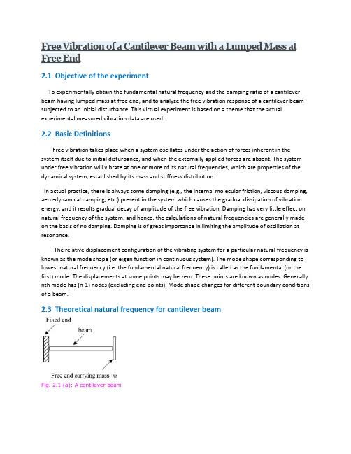
2.1 Objective of the experimentTo experimentally obtain the fundamental natural frequency and the damping ratio of a cantilever beam having lumped mass at free end, and to analyze the free vibration response of a cantilever beam subjected to an initial disturbance. This virtual experiment is based on a theme that the actual experimental measured vibration data are used.2.2 Basic DefinitionsFree vibration takes place when a system oscillates under the action of forces inherent in the system itself due to initial disturbance, and when the externally applied forces are absent. The system under free vibration will vibrate at one or more of its natural frequencies, which are properties of the dynamical system, established by its mass and stiffness distribution.In actual practice, there is always some damping (e.g., the internal molecular friction, viscous damping, aero-dynamical damping, etc.) present in the system which causes the gradual dissipation of vibration energy, and it results gradual decay of amplitude of the free vibration. Damping has very little effect on natural frequency of the system, and hence, the calculations of natural frequencies are generally made on the basis of no damping. Damping is of great importance in limiting the amplitude of oscillation at resonance.The relative displacement configuration of the vibrating system for a particular natural frequency is known as the mode shape (or eigen function in continuous system). The mode shape corresponding to lowest natural frequency (i.e. the fundamental natural frequency) is called as the fundamental (or the first) mode. The displacements at some points may be zero. These points are known as nodes. Generally nth mode has (n-1) nodes (excluding end points). Mode shape changes for different boundary conditions of a beam.2.3 Theoretical natural frequency for cantilever beamFig. 2.1 (a): A cantilever beamFig. 2.1 (b): The beam under free vibrationA cantilever beam with rectangular cross-section is shown in Fig. 2.1(a). Bending vibration can be generated by giving an initial displacement at the free end of the beam. Fig. 2.1(b) shows a cantilever beam undergoing a free vibration.When a system is subjected to free vibration and the system is considered as a discrete system in which the beam is considered as mass-less and the whole mass is concentrated at the free end of the beam. The governing equation of motion for such system will be,(2.1)Where m is a concentrated mass at the free end of the beam and k is the stiffness of the system. The transverse stiffness of a cantilever beam is given as (using strength of materials deflection formula, Timoshenko and Young, 1961),(2.2)Where E is the Young’s modulus of the beam material (it can be obtained by the tensile test of the standard specimen). The fundamental undamped circular natural frequency of the system is given as,(2.3)Where, m is an equivalent mass placed at the free end of the cantilever beam (of the beam and sensor masses). By substituting equation 2.2 into equation 2.3 we get,(2.4)The undamped natural frequency is related with the circular natural frequency as(2.5)the moment of inertia of the beam cross-section and for a circular cross-section it is given as, (2.6)Where, d is the diameter of cross section, and for a rectangular cross section(2.7)Where b and d are the breadth and depth of the beam cross-section as shown in Fig. 2.2. Dimensions of the beam material are given in Table 2.2Fig. 2.2: A rectangular cross-cross of the beamIn case of the test specimen, the beam mass is distributed over the length. However, by taking one-third of the total mass of beam at the free end (Thompson. 1961), the system can be assumed as discrete system. Hence,(2.8)Where m b is the mass of beam and is given asWhere , ρ is the mass density of the beam mate rial and V is the volume of the beam from the fixed end to the free end.The equivalent tip mass of a cantilever beam can be obtained as follows. Consider a cantilever beam as shown in Fig. 2.3 (a). Let be m1 the mass of the beam per unit length, l is the length of the beam, m b=m1l is total mass of the beam, and V max is the transverse velocity at the free end of beam and f is the force applied, E is the young’s modulus of the beam and I is the moment of inertia of the beam.Fig. 2.3(a): A cantilever beam with distributed m Fig. 2.3(b): The cantilever beam with a tip massConsider a small element of length dx at a distance x from the free end (Fig. 2.3 (a)). The beam displacement at this point is given by (Timoshenko and Young, 1961),(2.9)Here fl3/3EI is the deflection at free end of the cantilever beam. Now the velocity of the small element at distance x is given by,Hence, the kinetic energy of the element is given byand the total kinetic energy of the beam is(2.10)where m1l = m b. If we place a mass of 33/140m b at the free end of the beam and the beam is assumed to be of negligible mass, thenTotal kinetic energy possessed by the beam = (2.11)Hence two systems are dynamically same. Therefore, the continuous system of cantilever beam can be changed to single degree freedom system as shown in Fig. 2.3(b) by addingthe33 /140m b of mass at its free end.Values of the mass density for various beam materials are given in Table 2.1. If any contacting type of transducer is used for the vibration measurement, it should be placed at end of the beam and then the mass of transducer has to be added into the equivalent mass of the beam at the free end of the beam during the natural frequency calculation. If m t is the mass of transducer, then the total mass at the free end of the cantilever beam is given as,(2.12)2.4 Experimental setupFig. 2.4: An experimental setup for the free vibration of a cantilever beamExample 2.1:Obtain the undamped natural frequency of a steel beam with l = 0.45 m, d = 0.003 m, and b = 0.02 m. The mass of transducer at the free end = 18.2 gm.2.5 Photos of experimental setupFig. 2.5: Experimental setup of a cantilever beamFig. 2.5 shows an experimental setup of the cantilever beam. It includes a beam specimen of a particular geometry with a fixed end and at the free end an accelerometer is mounted to measure the free vibration response. The fixed end of beam is gripped with the help of clamp. For getting precise free vibration cantilever beam data, it is very important to ensure that clamp is tightened properly, otherwise it may not give fixed end conditions in the free vibration data.Fig. 2.6: A close view of the fixed end of the cantilever beamAccelerometer: It is the most common contacting type sensor for the vibration (i.e., acceleration, velocity or displacement) measurement. It is available with connecting cable as-well-as wireless type. It is pasted onto the surface by either using magnetic base, or by using adhesive glue, or by threaded screw (Fig. 2.7).Fig. 2.7: A close view of an accelerometer mounted on the free end of the beamThe basic principle of the measurement by an accelerometer is that it measures the force exerted by a body as a result of a change in the velocity of the body (i.e. which leads to acceleration). A moving body possesses an inertia which tends to resist change in velocity. The force caused by vibration or a change in motion causes the mass to "squeeze" the piezoelectric material which produces an electrical charge that is proportional to the force exerted upon it. Since the charge is proportional to the force, and the mass is a constant, hence the change is proportional to the acceleration.Laser Doppler Vibrometer (LDV): It is an instrument (Fig. 2.8) that is used to make non-contact vibration measurements of a surface. The laser beam from the LDV is directed at the surface of interest, and the vibration amplitude and frequency are extracted from the Doppler shift of the laser beam frequency due to the motion of the surface. The output of an LDV is generally a continuous analog voltage that is directly proportional to the target velocity component along the direction of the laser beam (give a line diagram of basic principle of the LDV).Fig. 2.8: A laser vibrometer systemFig. 2.9: A laser projector of a laser vibrometer fitted on a stand.Fig. 2.10: The controller for the laser vibrometerFig. 2.11: The laser generator of a laser vibrometerFig. 2.8 shows a rotational laser vibrometer. The complete setup consists of a projector (Fig.2.9), controller (Fig. 2.10), and laser generator (Fig. 2.11). To generate laser beam by the laser generator, all the settings related to the measurement are done in the controller. The laser goes to the reflector by an optical fiber cable. The beam is projected to the measurement surface and measurement signal is taken into the computer through a data-acquisition system. Rotational Laser Vibrometer (RLV): The optical measurement principle for the rotational vibrometer is based on laser interferometry. Use of the RLV is not limited to cylindrical parts. By using a special differential measurement process with two laser beams, independently of the shape of the object under investigation, only the rotational movement component is acquired and translational vibrations are predominantly suppressed. A schematic layout of the signal paths is shown in Fig. 2.12.Fig. 2.12: Principle of measurement of rotational laser vibrometerDynamic acquisition of rotational vibrations is possible in a frequency range from 0 Hz to 10 kHz. It also cover challenging measurement tasks e.g. in the order analysis in rotors. The interferometric process works continuously, i.e. in principle there is no limit to the angular resolution as for example, this limitation exist when using optical encoders with a finite number of divisions.Data acquisition system: Data acquisition system typically involves the conversion of analog signals and waveforms into digital values, and processing the values to obtain desired information. Data acquisition systems, as the name implies, are products and/or processes used to collect information to document or analyze some phenomenon. The components of measurement and data acquisition systems include (see Fig. 2.13) (i) Sensors that convert physical parameters to electrical signals, (ii) Signal conditioning circuitry to coerce sensor signals into a form that can be converted to digital values, and (iii) Analog-to-digital converters, which convert conditioned sensor signals to digital values.Fig. 2.13(a): An overall measurement systemFig. 2.13(b): Data acquisition systemData acquisition system receives voltage signal from sensors (e.g., accelerometer) and calibrate the data into equivalent physical quantity (e.g., acceleration) and send it to computer where by using a vibration measurement software these data can be analyzed in time history (e.g., acceleration-time, velocity-time or displacement-time) and in frequency domain (i.e., using FFT) Fig. 2.14.Fig. 2.14: A typical response with time and the corresponding FFT plotWhen the voltage signal from the accelerometer is sent to the data-acquisition system, it converts the signal to a mechanical vibration data (acceleration) and stores it to the computer.A typical screen-shot of a captured vibration signal by using vibration measurement software is plotted as shown in Fig. 2.14 and can be used for further analysis.。
混凝土工程concrete works一、材料袋装水泥bagged cement散装水泥bulk cement砂sand骨料aggregate商品混凝土commercial concrete现浇混凝土concrete-in-situ预制混凝土precast concrete预埋件embedment(fit 安装)外加剂admixtures抗渗混凝土waterproofing concrete 石场aggregate quarry垫块spacer二、施工机械及工具搅拌机mixer振动器vibrator电动振动器electrical vibrator 振动棒vibrator bar抹子(steel wood)trowel磨光机glasser混凝土泵送机concrete pump 橡胶圈rubber ring夹子clip混凝土运输车mixer truck自动搅拌站auto-batching plant 输送机conveyor塔吊tower crane汽车式吊车motor crane铲子shovel水枪jetting water橡胶轮胎rubber tires布袋cloth-bags塑料水管plastic tubes喷水雾spray water fog三、构件及其他专业名称截面尺寸section size(section dimension)混凝土梁concrete girder简支梁simple supported beam挑梁cantilever beam悬挑板cantilevered slab檐板eaves board封口梁joint girder翻梁upstand beam楼板floor slab空调板AC board飘窗bay window(suspending window)振捣vibration串筒 a chain of funnels混凝土施工缝concrete joint水灰比ratio of water and cement砂率sand ratio大体积混凝土large quantity of pouring混凝土配合比concrete mixture rate混凝土硬化hardening of concrete(in a hardening process 硬化中)规定时间regulated period质保文件quality assurance program设计强度design strength永久工程permanent works临时工程temporary works四、质量控制及检测不符合规格的non-standard有机物organic matters粘土clay含水率moisture content(water content)中心线central line安定性soundness (good soundness 优良的安定性)坍落度slump (the concrete with 18mm±20mm slump)混凝土养护concrete curing标养混凝土试件standard curing concrete test sample 同条件混凝土试件field-cure specimen收缩shrinkage初凝时间initial setting time终凝时间final setting time成品保护finished product protection混凝土试件concrete cube偏心受压eccentric pressing保护层concrete cover孔洞hole裂缝crack蜂窝honeycomb五、句子1,Usually we control the cement within 2% 我们将水泥的误差控制在2%2,Are there any pipe clogging happened during the concreting?浇筑混凝土中有堵管现象吗?3,Will the pipe be worn out very fast?管道磨损很快吗?4,T his embedment is fixed at 1500mm from the floor and 350mm from the left edge of the column. Would you measure the dimension by this meter?预埋件的位置在地面上1500mm,离柱边350mm。

基于模型分块逼近的三关节机器人鲁棒滑模控制马莉丽;钟斌【摘要】三关节机器人结构参数、作业环境的外界干扰及结构振动等不确定因素均会造成其动力学模型不确定,导致机器人关节位置镇定或轨迹跟踪控制器的设计具有一定的难度。
为此,设计三个RBF(Radical Basis Function)神经网络分别对机器人不确定模型中的三个不确定项进行分块逼近,得到三个不确定项的估计信息,从而得出机器人估计模型,神经网络的权值采用适应算法。
针对机器人估计模型设计鲁棒滑模控制律,其中鲁棒项用于克服神经网络建模误差。
通过定义 Lya-punov函数,证明了控制系统是稳定的。
实验结果也表明了三关节均约在1 s时达到期望位置或跟踪期望轨迹,位置镇定误差或轨迹跟踪误差也快速、稳定地趋于零。
%Generally,the dynamic model of robot with three-j oint is undetermined due to three-j oint robot’s uncertain structure parameters,working environment’s external interfere and struc-tural vibration.Accordingly,it is difficult to control the robot’s joints’position stabilizing and traj ectory tracking and controller’s design due to the dynamic model’s uncertainty.Therefore, three designed RBF(Radical Basis Function)neural networks are used to respectively model the three undetermined terms of the undetermined robot dynamic model,with partition approxima-ting the three-joint robot.Three undetermined terms’estimation information is respectively ob-tained,with the robot’s estimation model obtained.The neural networks’weights are obtained through the adaptive algorithm.The robust sliding mode control law is designed based on the ro-bot’s estimation model.The control law’srobust term is used to overcome the neural networks’ modeling er ror.The control system’s stability is proved by defining Lyapunov function.The simulation experiments test verifies that three joints can trace ideal trajectory and reach an ideal position in 1 s,and stabilization error and tracking error can fast and stably approximate to zero.【期刊名称】《西安理工大学学报》【年(卷),期】2016(032)004【总页数】6页(P437-442)【关键词】三关节机器人;模型分块逼近;关节控制;RBF神经网络【作者】马莉丽;钟斌【作者单位】中国人民武装警察部队工程大学装备工程学院,陕西西安 710086;中国人民武装警察部队工程大学装备工程学院,陕西西安 710086【正文语种】中文【中图分类】TP242.2三关节机器人(以下简称机器人)结构紧凑,所占空间小,灵活性强,工作空间较大,避障性好,广泛应用于工业机器人中。
过程装备与控制工程专业英语学院:化学化工学院1.Static Analysis of Beams⑴ A bar that is subjected to forces acting trasverse to its axis is called a beam. In this section weconsider only a few of the simplest types of beams, such as those shown in Flag.1.2. In every instance it is assumed that the beam has a plane of symmetry that is parallel to the plane of the figure itself. Thus , the cross section of the beam has a vertical axis of symmetry .Also,it is assumed that the applied loads act in the plane of symmetry ,and hence bending of the beam occurs in that plane. Later we will consider a more general kind of bending in which the beam may have an unsymmetrical cross section.⑵ The beam in Fig.1.2, with a pin support at one end and a roller support at the other, is calleda simply support beam ,or a simple beam . The essential feature of a simple beam is that both ends of the beam may rotate freely during bending, but the cannot translate in lateral direction. Also ,one end of the beam can move freely in the axial direction (that is, horizontal). The supports of a simple beam may sustain vertical reactions acting either upward or downward .⑶ The beam in Flg.1.2(b) which is built-in or fixed at one end and free at the other end, iscalled a cantilever beam. At the fixed support the beam can neither rotate nor translate, while at the free end it may do both. The third example in the figure shows a beam with an overhang. This beam is simply supported at A and B and has a free at C.⑷ Loads on a beam may be concentrated forces, such as P1 and P2 in Fig.1.2(a) and (c), ordistributed loads loads, such as the the load q in Fig.1.2(b), the intesity. Distributed along the axis of the beam. For a uniformly distributed load, illustrated in Fig.1.2(b),the intensity is constant; a varying load, on the other hand, is one in which the intensity varies as a function of distance along the axis of the beam.⑸ The beams shown in Fig.1.2 are statically determinate because all their reactions can bedetermined from equations of static equilibrium. For instance ,in the case of the simple beam supporting the load P 1 [Fig.1.2(a)], both reactions are vertical, and tehir magnitudes can be found by summing moments about the ends; thus,we findL a L P R A )(1-= LL P R B 1= The reactions for the beam with an overhang [Fig.1.2 (c)]can be found the same manner.⑹ For the cantilever beam[Fig.1.2(b)], the action of the applied load q is equilibrated by avertical force RA and a couple MA acting at the fixed support, as shown in the figure. From a summation of forces in certical direction , we include thatqb R A =, And ,from a summation of moments about point A, we find)2(b a qb M A +=, The reactive moment MA acts counterclockwise as shown in the figure.⑺ The preceding examples illustrate how the reactions(forces and moments) of staticallydeterminate beams requires a considerition of the bending of the beams , and hence this subject will be postponed.⑻ The idealized support conditions shown in Fig.1.2 are encountered only occasionally inpractice. As an example ,long-span beams in bridges sometimes are constructionn with pin and roller supports at the ends. However, in beams of shorter span ,there is usually some restraint against horizonal movement of the supports. Under most conditions this restraint has little effect on the action of the beam and can be neglected. However, if the beam is very flexible, and if the horizonal restraints at the ends are very rigid , it may be necessary to consider their effects.⑼ Example Find the reactions at the supports for a simple beam loaded as shown infig.1.3(a ). Neglect the weight of the beam.⑽ Solution The loading of the beam is already given in diagrammatic form. The nature of thesupports is examined next and the unknow components of reactions are boldly indicated on the diagram. The beam , with the unknow reaction components and all the applied forces, is redrawn in Fig.1.3(b) to deliberately emphasiz this important step in constructing a free-body diagram. At A, two unknow reaction components may exist , since roller. The points of application of all forces are carefully noted. After a free-body diagram of the beam is made, the equations of statics are applied to abtain the sollution.∑=0x F ,R Ax =0∑+=0A M ,2000+100(10)+160(15)—R B =0,R B =+2700lb ↑∑+=0BM ,RAY(20)+2000—100(10)—160(5)=0,RAY=—10lb ↓ Check :∑+↑=0FX ,—10—100—160+270=0 ⑾ Note that ∑=0x F uses up one of the three independent equations of statics, thus only twoadditional reaction compones may be determinated from statics. If more unknow reaction components or moment exist at the support, the problem becomes statically indeterminate. ⑿ Note that the concentrated moment applied at C enters only the expressions for summationmoments. The positive sign of RB indicates that the direction of RB has been correctly assumed in Fig.1.3(b). The inverse is the case of RAY ,and the vertical reaction at a is downward. Noted that a check on the arithmetical work is available if the caculations aremade as shown.横梁的静态分析⑴ 一条绕其轴水平放置的棒就是所谓的横梁,本章节我们将研究最简单的横梁模型形式,如图1.2所示。
第50卷增刊建筑结构Vol.50 S2国家能源集团主楼维修改造项目技术要点研究白树杨,周袁凯,郁银泉,刘国友,蒋航军,韩彬(中国建筑标准设计研究院有限公司,北京100048)[摘要]国家能源集团主楼维修改造项目由五星级酒店建筑改造为办公建筑,改造难点主要有南侧悬挑梁板接长、斜框柱拆除、钢斜撑托柱转换、斜框柱加固改造等。
介绍了本工程按后续使用年限为40年确定的抗震设计依据及地震设计参数;原结构拆除后新建结构采用钢结构方案的优势;改造后结构整体计算结果、需要加固的部位和加固措施;特殊关键节点的设计原则和设计思路,以及节点构造详图和现场实物图片。
[关键词]国家能源集团;加固改造;钢筋混凝土结构;钢结构;节点构造中图分类号:TU398+.2,TU391 文献标识码:A 文章编号:1002-848X(2020)S2-0610-06Research on the technical points of the main building maintenance andreconstruction project of China Energy GroupBAI Shuyang, ZHOU Yuankai, YU Yinquan, LIU Guoyou, JIANG Hangjun, HAN Bin(China Institute of Building Standard Design and Research, Beijing 100048, China)Abstract:The main building maintenance and reconstruction project of China Energy Group was to transform the five-star hotel building into the office building. Difficulties in the reconstruction mainly included the extension of cantilever beams and slabs on the south side, the removal of inclined frame column, the conversion of steel diagonal support column, and the reinforcement and reconstruction of inclined frame column. The basis and parameters of seismic design of the project based on the subsequent service life of 40 years were introduced. The advantage of adopting steel structure scheme for the new structure after the dismantling of the original structure was introduced. The overall calculation results of the reconstructed structure, the parts that need to be strengthened, and the reinforcement measures were presented. In addition, the design principles and ideas of special key joints, the detailed drawings of joint, and the physical pictures on site were introduced.Keywords:China Energy Group; reinforcement and reconstruction; reinforced concrete structures; steel structures;reconstruction; joint construction1 工程概况1.1 原建筑结构概况国家能源集团主楼维修改造项目,位于北京市东城区西滨河路22号、25号,地处中轴路与北二环路交汇点的东北角。
Interaction and Multiscale Mechanics, Vol. 2, No. 3 (2009) 223-233223The effects of stiffness strengthening nonlocal stress and axial tension on free vibration of cantilever nanobeamsC.W. Lim†Department of Building and Construction, City University of Hong Kong,Tat Chee Avenue, Kowloon, Hong Kong SAR, P.R. ChinaC. LiDepartment of Building and Construction, City University of Hong Kong,Tat Chee Avenue, Kowloon, Hong Kong SAR, P.R. ChinaDepartment of Modern Mechanics, University of Science and Technology of China,Hefei, Anhui 230026, P.R. ChinaJ. L. YuDepartment of Modern Mechanics, University of Science and Technology of China,Hefei, Anhui 230026, P.R. China(Received May 25, 2009, Accepted July 7, 2009)Abstract.This paper presents a new nonlocal stress variational principle approach for the transverse free vibration of an Euler-Bernoulli cantilever nanobeam with an initial axial tension at its free end. The effects of a nanoscale at molecular level unavailable in classical mechanics are investigated and discussed.A sixth-order partial differential governing equation for transverse free vibration is derived via variational principle with nonlocal elastic stress field theory. Analytical solutions for natural frequencies and transverse vibration modes are determined by applying a numerical analysis. Examples conclude that nonlocal stress effect tends to significantly increase stiffness and natural frequencies of a nanobeam. The relationship between natural frequency and nanoscale is also presented and its significance on stiffness enhancement with respect to the classical elasticity theory is discussed in detail. The effect of an initial axial tension, which also tends to enhance the nanobeam stiffness, is also concluded. The model and approach show potential extension to studies in carbon nanotube and the new result is useful for future comparison.Keywords:cantilever nanobeam; free vibration; initial tension; nonlocal elasticity; nonlocal stress.1.IntroductionWith the rapid development of current technologies, miniaturized structures with nanoscale †Professor, Corresponding Author, E-mail: bccwlim@.hk224 C. W. Lim, C. Li and J. L. Yufeatures can be precisely manufactured and applied in the so-called nano-electro-mechanical systems (NEMS) (Cagin et al. 1996, Gao and Zhao 2006, Jonsson et al. 2008). Carbon nanotubes and elastic beams with nanoscale thickness are most popular in these systems (Chen et al. 2008, Sato and Shima 2008, Unnikrishnan Zhao et al. 2008, Aluru 2008). Besides the load bearing capability, they can also be used as sensors and micrometers to detect the adsorption and to measure the interaction of certain molecules on their surface. This is because the adsorption and interaction may significantly alter the mechanical properties of the structures which will eventually lead to changes in mechanical behavior of the elements, including deformation and free vibration. Establishing an accurate model and relationship between load and vibration behaviour is thus a key issue for NEMS designs. Unfortunately, the classical elasticity theory fails to give such a relation because it lacks an intrinsic length scale and thus cannot capture the size-dependence vibration, as observed experimentally for nanoscale nanobeams. That is the reason why much attention has been paid to the analysis of classical structures with classical continuum mechanics, a subject of intensive research recently (Oz et al. 2001, Na et al. 2003, Wang et al. 2005, Parker and Orloske 2006).There are molecular structures that can be modeled as nanobeams depending on geometry and configuration. One of them is a cantilever nanobeam and it is, in fact, one of the most important components in NEMS because it can be both a sensor as well as an actuator. Recently, there exists intensive research on dynamic behavior of nanobeams because of their potential prospects in NEMS or nano-machine components. Although nanobeams have found practical applications, analysis in this field has been lacking in particular the dynamics and vibration of pre-tensioned nanobeams.The nonlocal elasticity theory was first developed by Eringen (1972, 1983) and Eringen and Edelen (1972) in the early 1970s. In recent years, the nonlocal stress theory and modeling for nanobeams have received increasing interest in nanomechanics research. This nonlocal continuum theory regards the stress at a point as a function of the strain states of all points in the body while the classical continuum mechanics assumes the stress state as only dependent uniquely on the strain state at that same point. This is in accordance with the atomic theory of lattice dynamics and experimental observations on phonon dispersion and so an internal size scale is introduced into the constitutive equations as a material parameter. In the limit when the effects of strains at other points are neglected, the nonlocal continuum theory reverts to the classical theory. The nonlocal elasticity theory has been applied in nanomechanics including lattice dispersion of elastic waves, wave propagation in composites, dislocation mechanics, fracture mechanics, surface tension fluids, etc. (Y u 1985, Yakobson et al. 1996, Reddy and Wang 1998, Shibutani et al. 1998, Mikkelsen and Tvergaard 1999, Sudak 2003, He et al. 2004, Zhang et al. 2005, Lu et al. 2006, Hu et al. 2008). In recent work, Lim and Wang (2007) Pintroduced an asymptotic representation of the one-dimensional nanobeam model via a variational principle approach and their nanobeam bending solutions based on nonlocal stress model were useful to engineers who designed micro- or nano-electromechanical devices. In another research by Tounsi et al. (2008), it was concluded that the scale coefficient was radius dependent.In this paper, we attempt to investigate the nonlocal stress effects on a cantilever nanobeam with an axial tension and subsequently the study of its transverse free vibration. The model is described by a new sixth-order partial differential equation in dimensionless quantities via an exact variational principle approach. It is found that the presence of an initial tension and nonlocal stress do play significant roles in the free vibration behavior of a cantilever nanobeam in which the structuralThe effects of stiffness strengthening nonlocal stress and axial tension on free vibration of cantilever nanobeams 225stiffness is greatly enhanced. The results are useful for designing nanoscale devices as components in NEMS.2. Problem Definition and ModelingConsider a uniform cantilever nanobeam with axial coordinate x , fixed at x =0 and an initial axial tension N at the free end. The length of the nanobeam is L and the transverse deformation is w . The governing equation for transverse free vibration can be obtained by variational principle as follows.For free vibration of a nanobeam without dissipation, energy changes from strain to kinetic forms and vibratory motion sustains at its natural frequency. The strain energy density u at an arbitrary point of a deformed nanobeam is given by (Lim 2008)(1)where is the dimensionless coordinate, the nonlocal nanoscale parameter, E the Young’s modulus, the normal strain in axial direction and a constant dependent on eachmaterial, a an internal characteristic length (e.g. lattice parameter, C-C bond length, granular distance, etc.) (Eringen 1983). The total strain energy in the deformed body is(2)Following the variational principle, the variation of strain energy can be finally expressed as(3)where , dA is the cross-sectional area moment of inertial and y is the transversecoordinate. In the presence an axial tension N at the free end, the work done is(4)u 12--E εxx 212--E 1–()n 1+n 1=∞∑τ 2n d n εxx dx n------------⎝⎠⎜⎟⎛⎞2E τ 2n 1+()1–()m 1+d m εxx dx m -------------d 2n 1+()m –()εxx dx 2n 1+()m –()---------------------------------m 1=n ∑⎩⎭⎨⎬⎧⎫n 1=∞∑++=x xL--=τe 0a L -------=εxx e 0U u Vd V∫=δU EI L -----2n 3–()τ 2n 1–()∂2n 1+()w ∂x2n 1+()--------------------n 1=∞∑–δwdx 01∫= EIL-----2n 3–()τ 2n 1–()∂2n 1+()w∂x 2n 1+()--------------------n 1=∞∑δw 2n 3–()τ 2n 1–()∂2nw ∂x 2n -----------∂δw ∂x----------n 1=∞∑–+ 2n 1–()τ 2n ∂2n 1+()w ∂x 2n 1+()--------------------∂2δw ∂x 2------------n 1=∞∑2n τ2n 1+()∂2n 1+()w ∂x 2n 1+()--------------------∂3δw ∂x 3------------n 1=∞∑2n 1–()τ2n 1+()∂2n 1+()w ∂x 2n 1+()--------------------∂4δw ∂x 4------------n 1=∞∑+–+2n 1–()τ2n 2+()∂2n 1+()w ∂x 2n 1+()--------------------∂5δw ∂x 5------------n 1=∞∑2n 1–()τ2n 3+()∂2n 3+()w ∂x 2n 3+()--------------------∂6δw ∂x 6------------n 1=∞∑ +…+–w xL --=I y 2A∫∫=V N 2---∂w ∂x ------⎝⎠⎛⎞2x d 0L ∫NL 2-------∂w ∂x ------⎝⎠⎛⎞2x d 01∫==226 C. W. Lim, C. Li and J. L. YuV ariation of the work above is given by(5)For a nanobeam in free vibration, the kinetic energy due to transverse motion is(6)where in which t , T are the time coordinate and period of vibration, respectively, and ρ isthe density per unit length. Then, variation of the kinetic energy is given by(7)For static equilibrium, the variational principal requires that (8)which results in(9)Since cannot vanish, hence the governing equation of motion from Eq. (9) is(10)where is the dimensionless axial tension, is the dimensionless density and the boundary conditions are obtained asδV NL ∂w ∂x ------01∫∂δw∂x ----------x d NL ∂w ∂x ------δw 01∂2w ∂x2--------01∫δw x d –==E k ρ2--∂w ∂t ------⎝⎠⎛⎞2x d 0L ∫ρL 32T2--------∂w ∂t ------⎝⎠⎛⎞2x d 01∫==t tT--=δE k ρL 3T 2--------∂w ∂t ------01∫∂δw ∂t ----------x d ρL 3T 2--------∂w ∂t ------δw 01∂2w ∂t2--------01∫δw x d –==δU V –E k –()0=0EIL-----2n 3–()τ 2n 1–()∂2n 1+()w ∂x 2n 1+()--------------------n 1=∞∑–NL 2EI ---------∂2w ∂x 2--------ρL 4EIT 2-----------∂2w ∂t 2--------++δw x d 01∫=EI L -----2n 3–()τ 2n 1–()∂2n 1+()w ∂x2n 1+()--------------------n 1=∞∑NL 2EI ---------–∂w ∂x ------ρL 4EIT 2-----------–∂w ∂t ------δw ⎩⎨⎧+2n 3–()τ 2n 1–()∂2nw ∂x 2n -----------∂δw ∂x ----------n 1=∞∑–2n 1–()τ 2n ∂2n 1+()w ∂x 2n 1+()--------------------∂2δw ∂x 2------------n 1=∞∑+2n τ 2n 1+()∂2n 1+()w ∂x 2n 1+()--------------------∂3δw ∂x 3------------n 1=∞∑–2n 1–()τ 2n 1+()∂2n 1+()w ∂x 2n 1+()--------------------∂4δw∂x 4------------n 1=∞∑+2n 1–()τ2n 2+()∂2n 1+()w ∂x 2n 1+()--------------------∂5δw ∂x 5------------n 1=∞∑2n 1–()τ2n 3+()∂2n 3+()w ∂x 2n 3+()--------------------∂6δw ∂x 6------------n 1=∞∑ +…+–⎭⎬⎫01δw 2n 3–()τ2n 1–()∂2n 1+()w ∂x 2n 1+()--------------------N ∂2w ∂x 2--------ρ∂2w∂t2--------++n 1=∞∑–0=N NL 2EI ---------=ρρL4EIT2-----------=The effects of stiffness strengthening nonlocal stress and axial tension on free vibration of cantilever nanobeams 227(11)To investigate the nonlocal stress effect, the first nonlocal terms in Eqs. (10) and (11), which are the most important terms reflecting the nonlocal effects, are retained. The governing equation of motion with the most significant nonlocal terms are obtained as(12)and the corresponding boundary conditions are(13)For linear free vibration of a nanobeam, the vibration modes are harmonic in time. From Eq. (12),time-dependent transverse deformation of nanobeam can be represented by(14)where is the dimensionless vibration amplitude, denotes the vibration mode2n 3–()τ 2n 1–()∂2n 1+()w ∂x2n 1+()--------------------N –∂w ∂x ------ρ–∂w ∂t ------n 1=∞∑0=or w 0=2n 3–()τ 2n 1–()∂2nw ∂x2n-----------0=n 1=∞∑or ∂w ∂x ------0=2n 1–()τ 2n ∂2n 1+()w ∂x2n 1+()--------------------0=n 1=∞∑or ∂2w ∂x 2--------0=2n τ 2n 1+()∂2n 1+()w ∂x2n 1+()--------------------0=n 1=∞∑or ∂3w ∂x 3--------0=2n 1–()τ 2n 1+()∂2n 1+()w ∂x2n 1+()--------------------0=n 1=∞∑or ∂4w ∂x 4--------0=2n 1–()τ 2n 2+()∂2n 1+()w ∂x2n 1+()--------------------0=n 1=∞∑or ∂5w ∂x 5--------0=2n 1–()τ 2n 3+()∂2n 3+()w ∂x2n 3+()--------------------0=n 1=∞∑or ∂6w ∂x 6--------0=or⎭⎪⎪⎪⎪⎪⎪⎪⎪⎪⎪⎪⎪⎪⎬⎪⎪⎪⎪⎪⎪⎪⎪⎪⎪⎪⎪⎪⎫x 01,=……τ2∂6w ∂x 6--------∂4w ∂x 4--------N ∂2w ∂x 2--------ρ∂2w ∂t 2--------+++–0=∂3w ∂x 3--------τ2∂5w ∂x5--------N –∂w ∂x ------ρ–∂w ∂t ------+–0=or w 0=∂2w ∂x 2--------–τ2∂4w ∂x 4--------+0=or ∂w∂x ------0=τ2∂3w ∂x 3--------3τ4∂5w ∂x 5--------+0=or ∂2w ∂x 2--------0=⎭⎪⎪⎪⎪⎬⎪⎪⎪⎪⎫at x 01,=w x t ,()W n x ()ei ωn t=W n x ()n 123K ,,,=228 C. W. Lim, C. Li and J. L. Yunumber and is the dimensionless natural frequency. Substituting Eq. (14) into Eq. (12), the equation of motion becomes(15)Further substituting Eq. (14) into Eq. (13), the boundary conditions become(16)For free vibration, the deflection of a nanobeam can be represented by(17)where as an arbitrary nonzero constant. Substituting this expression into Eq. (15), we obtain adispersion relation as(18)Since Eq. (18) is a sixth-order polynomial in terms of , the six roots are denoted by , respectively. Because only linear free vibration is concerned, the superposition of the six solutions with respect to each root is also a solution of the governing Eq. (15). Hence(19)where are six constants of integration associated with Eq. (15) which is a sixth-order ordinary differential equation.3. Numerical Examples and Effects on Natural FrequenciesTo illustrate the effect of nanoscale parameter and initial axial tension on the transverse vibration of a nanobeam, the following numerical example for a cantilever nanobeam is presented and discussed in detail.In defining boundary conditions of nonlocal beam models, the consistent expressions such as bending moment or shear force should be given by the nonlocal forms but not their classical counterparts with . It is likely to be overlooked in some of the applications (Zhang et al .2005), where the classical expressions for the boundary bending moments were still used. In the present work, for a cantilever nanobeam fixed at and free at , the dimensionless nonlocal boundary conditions from Eq. (16) are given byωn τ2d 6W n dx 6-------------d 4W n dx 4-------------–N d 2W n dx 2-------------–ρωn 2W n +0=d 3W n dx 3-------------τ2d 5W ndx5------------N –dW n dx ---------i ωn –ρW n +–0=or W n 0=d 2W n dx 2------------–τ2d 4W ndx 4------------+0=or dW ndx ---------0=τ2d3W n dx 3------------3τ4d 5W n dx5------------+0=or d 2W ndx 2------------0=⎭⎪⎪⎪⎪⎬⎪⎪⎪⎪⎫at x 01,=W n x ()C n ei βjn x=C n τ2βn 6βn 4N βn 2ρωn 2––+0=βn βjn j 12K 6,,,=()βjn W n x ()C 1n ei β1n xC 2n ei β2n xC 3n ei β3n xC 4n ei β4n xC 5n ei β5n xC 6n ei β6n x+++++=C jn j 12K 6,,,=()τ0=x 0=x 1=The effects of stiffness strengthening nonlocal stress and axial tension on free vibration of cantilever nanobeams 229(20)Substituting Eq. (19) into Eq. (20), the equations can be expressed in a matrix form as(21)For nontrivial solutions, the determinant of matrix (21) must be zero, or(22)W n 0()0; dW n 0()dx ------------------0; τ2d 3W n 0()dx 3---------------------3τ4d 5W n 0()dx5---------------------+0;===d 3W n 1()dx 3---------------------–τ2d 5W n 1()dx5---------------------N dW n 1()dx ------------------i ωn ρW n 1()––+0;=d 2W n 1()dx 2---------------------–τ2d 4W n 1()dx4---------------------+0; d 2W n 1()dx 2---------------------0==111β1n β2n β3n β1n 33τ2β1n 5–β2n 33τ2β2n 5–β3n 33τ2β3n 5–β1n 2e i β1n β2n 2e i β2n β3n 2e i β3n e i β1n β1n 3τ2β1n 5N β1n ωn ρ––+()e i β2n β2n 3τ2β2n 5N β2n ωn ρ––+()e i β3n β3n 3τ2β3n 5N β3n ωn ρ––+()β1n 4e i β1n β2n 4e i β2n β3n 4e i β3n ⎝⎜⎜⎜⎜⎜⎜⎜⎜⎜⎜⎛111β4nβ5nβ6nβ4n 33τ2β4n5–β5n 33τ2β5n5–β6n 33τ2β6n5–β4n 2ei β4nβ5n 2ei β5nβ6n 2ei β6n ei β4nβ4n 3τ2β4n 5N β4n ωn ρ––+()e i β5nβ5n 3τ2β5n 5N β5n ωn ρ––+()ei β6nβ6n 3τ2β6n 5N β6n ωn ρ––+()β4n 4ei β4nβ5n 4ei β5nβ6n 4ei β6n⎠⎟⎟⎟⎟⎟⎟⎟⎟⎟⎞C 1n C 2n C 3n C 4n C 5n C 6n ⎝⎠⎜⎟⎜⎟⎜⎟⎜⎟⎜⎟⎜⎟⎜⎟⎜⎟⎛⎞0=111β1nβ2nβ3nβ1n 33τ2β1n5–β2n 33τ2β2n5–β3n 33τ2β3n5–β1n 2ei β1nβ2n 2ei β2nβ3n 2ei β3n ei β1nβ1n 3τ2β1n 5N β1n ωn ρ––+()e i β2nβ2n 3τ2β2n 5N β2n ωn ρ––+()e i β3nβ3n 3τ2β3n 5N β3n ωn ρ––+()β1n 4ei β1nβ2n 4ei β2nβ3n 4ei β3n111β4nβ5nβ6nβ4n 33τ2β4n5–β5n 33τ2β5n5–β6n 33τ2β6n5–β4n 2ei β4nβ5n 2ei β5nβ6n 2ei β6nei β4nβ4n 3τ2β4n 5N β4n ωn ρ––+()e i β5nβ5n 3τ2β5n 5N β5n ωn ρ––+()e i β6nβ6n 3τ2β6n 5N β6n ωn ρ––+()β4n 4ei β4nβ5n 4ei β5nβ6n 4ei β6n=230 C. W. Lim, C. Li and J. L. YuBy combining Eqs. (18) and (22), the seven unknown quantities and can be solved. Subsequently, substituting the results into Eqs. (21), the analytical solutions of n th vibration mode in Eq. (19) and transverse deformation in Eq. (14) can be solved to the extent of an arbitrary constant, for instance .For comparison with the classical elasticity theory, the natural frequency for free vibration of a classical cantilever beam without initial tension is (Liu et al . 1998)(23)where for is the physical vibration frequencies from the classical vibration theory and can be obtained from the following transcendental equationβjn j 123456,,,,,=()ωn W n w C 1n 0≠ωn ()c λn 2EI ρ-----= n 123…,,=,ωn ()c n 123…,,=λn Fig. 1 Effects of nanoscale and initial tension on the first two natural frequencies for ρ0.01=Fig. 2 Effects of nanoscale and initial tension on the first two natural frequencies for ρ0.03=The effects of stiffness strengthening nonlocal stress and axial tension on free vibration of cantilever nanobeams 231(24)where L is the length of the classical cantilever beam. Solving Eq. (24), the first two dimensionless natural frequencies are approximately; (25a,b)Effects of nanoscale parameter and initial tension on the first two natural frequencies are shown inFig. 1 for . The classical solutions in Eq. (25a,b) are also presented and compared.Similarly, the relationships for and are illustrated in Figs. 2 and 3,respectively, to indicate the nonlocal effects as well as varying dimensionless density on the first two natural frequencies.It is observed that the nanoscale and initial axial tension affect the natural frequencies very significantly. The nonlocal effect enhances nanobeam stiffness and thus causes higher frequencies as compared with the classical solutions. Specifically, the first two natural frequencies increase with increasing τ, which indicates that stronger nonlocal effects cause higher natural frequencies.Similarly, it is also observed that stronger initial axial tension induces higher nanobeam stiffness and thus higher vibration frequency. In general, with certain increase in τ or N , the first two vibration frequencies presented in Figs. 1 to 3 could be more than double of their original values.In these three figures, the classical vibration solutions and , as defined in Eq. (25),assume identical values because these are dimensionless parameters are not only independent of nonlocal effects but also invariant for varying density. However, for a cantilever nanobeam with nonlocal effects, it is obvious that a larger density ρ leads to a lower frequency by comparing Figs.1, 2 and 3. This observation shows the unique features of vibration characteristics which are size-dependent and not noticeable in classical vibration theory.λn L ()cos λn L ()1+cosh 0=ω1()c λ12L 2ω1()c L2ρEI ----- 1.8752===ω2()c λ22L 2ω2()c L 2ρEI----- 4.6942===ρ0.01=ρ0.03=ρ0.05=ω1()c ω2()c Fig. 3 Effects of nanoscale and initial tension on the first two natural frequencies for ρ0.05=232 C. W. Lim, C. Li and J. L. Yu4. ConclusionsIn this paper, the free transverse vibration of a cantilever nanobeam with initial axial tension is solved based on a new nonlocal stress field theory. A high-order partial differential equation which governs the vibration behavior is obtained via the variational principle. Applying a numerical method, the effects of nanoscale parameter, initial tension, as well as the dimensionless density on natural frequencies are investigated in detail. It is found that the nanoscale parameter and initial tension induce higher frequencies as compared with the classical beam solutions while the dimensionless density results in lower frequencies. Stiffness of a nanobeam is greatly enhanced by the presence of a nanoscale as well as an initial axial tension. In summary, unique and significant, size-dependent vibration characteristics not present in classical vibration theory are noted in nonlocal nanobeam vibration.AcknowledgementsThis work was supported by a collaboration scheme from University of Science and Technology of China-City University of Hong Kong Joint Advanced Research Institute and by City University of Hong Kong [Project No. 7002472 (BC)].ReferencesCagin, T., Che, J.W., Gardos, M.N., Fijany, A. and Goddard, W.A. (1999), “Simulation and experiments on friction and wear of diamond: a material for MEMS and NEMS application”, Nanotechnology, 10(3), 278-284.Chen, C.S., Wang, C.K. and Chang, S.W. (2008), “Atomistic simulation and investigation of nanoindentation, contact pressure and nanohardness”, Interact. Multi. Mech., 1(4), 411-422.Eringen, A.C. (1972), “Nonlocal polar elastic continua”, Int. J. Eng. Sci., 10(1), 1-16.Eringen, A.C. (1983), “On differential equations of nonlocal elasticity and solutions of screw dislocation and surface waves”, J. Appl. Phys., 54(9), 4703-4710.Eringen, A.C. and Edelen, D.G.B. (1972), “On nonlocal elasticity”, Int. J. Eng. Sci., 10(3), 233-248.Gao, J.G. and Zhao. Y.P. (2006), “Dynamic stability of electrostatic torsional actuators with van der Waals effect”, Int. J. Solids Struct., 43(3-4), 675-685.He, L.H., Lim, C.W. and Wu, B.S. (2004), “A continuum model for size-dependent deformation of elastic films of nano-scale thickness”, Int. J. Solids Struct., 41(3-4), 847-857.Hu, Y.G., Liew, K.M., Wang, Q., He, X.Q. and Yakobson, B.I. (2008), “Nonlocal shell model for elastic wave propagation in single- and double-walled carbon nanotubes”, Int. J. Solids Struct., 56(12), 3475-3485. Jonsson, L.M., Santandrea, F., Gorelik, Y.K., Shekhter, R.I. and Jonson, M. (2008), “Self-organization of irregular nanoelectromechanical vibrations in multimode shuttle structures”, Phys. Rev. Lett., 100(18), 186802.Lim, C.W. (2008), “A discussion on the nonlocal elastic stress field theory for nanobeams”, The 11th East Asia-Pacific Conference on Structural Engineering & Construction (EASEC-11), Taipei, November.Lim, C.W. and Wang, C.M. (2007), “Exact variational nonlocal stress modeling with asymptotic higher-order strain gradients for nanobeams”, J. Appl. Phys., 101(5), 054312.Liu, Y.Z., Chen, W.L. and Chen, L.Q. (1998), Vibration Mechanics. Higher Education Press, Beijing.Lu, P., Lee, H.P., Lu, C. and Zhang, P.Q. (2006), “Dynamic properties of flexural beams using a nonlocal elasticity model”, J. Appl. Phys., 99(7), 073510.Mikkelsen, L.P. and Tvergaard, V. (1999), “A nonlocal two-dimensional analysis of instabilities in tubes under internal pressure”, J. Mech. Phys. Solids, 47(4), 953-969.The effects of stiffness strengthening nonlocal stress and axial tension on free vibration of cantilever nanobeams233 Na, S., Librescu, L. and Shim, J.K. (2003), “Modeling and bending vibration control of nonuniform thin-walled rotating beams incorporating adaptive capabilities”, Int. J. Mech. Sci., 45(8), 1347-1367.Oz, H.R., Pakdemirli, M. and Boyaci, H. (2001), “Non-linear vibrations and stability of an axially moving beam with time-dependent velocity”, Int. J. Nonlin. Mech., 36, 107-115.Parker, R.G. and Orloske, K. (2006), “Flexural-torsional buckling of misaligned axially moving beams: vibration and stability analysis”, Int. J. Solids Struct., 43(14-15), 4323-4341.Reddy, J.N. and Wang, C.M. (1998), “Deflection relationships between classical and third-order plate theories”, Acta Mech. Sinica, 130 (3-4), 199-208.Sato, M. and Shima, H. (2008), “Buckling characteristics of multiwalled carbon nanotubes under external pressure”, Interact. Multi. Mech., 2(2), 209-222.Shibutani, Y., Vitek, V. and Bassani, J.L. (1998), “Nonlocal properties of inhomogeneous structures by linking approach of generalized continuum to atomistic model”, Int. J. Mech. Sci., 40(2-3), 129-137.Sudak, L.J. (2003), “Column buckling of multiwalled carbon nanotubes using nonlocal continuum mechanics”, J. Appl. Phys., 94(11), 7281-7287.Tounsi, A., Heireche, H., Berrabah, H.M., Benzair, A. and Boumia, L. (2008), “Effect of small size on wave propagation in double-walled carbon nanotubes under temperature field”, J. Appl. Phys., 104(10), 104310.Unnikrishnan, V.U., Reddy, J.N., Banerjee, D. and Rostam-Abadi, F. (2008), “Thermal characteristics of defective carbon nanotube-polymer nanocomposites”, Interact. Multi. Mech., 1(4), 397-409.Wang, Y.F., Huang, L.H. and Liu, X.T. (2005), “Eigenvalue and stability analysis for transverse vibrations of axially moving strings based on Hamiltonian dynamics”, Acta Mech. Sinica, 21, 485-494.Yakobson, B.I., Brabec, C.I. and Bernholc, J. (1996), “Nanomechanics of carbon tubes: Instabilities beyond linear response”, Phys. Rev. Lett., 76(14), 2511-2514.Y u, J.L. (1985), “Progress and applications of solid mechanics considering microstructure”, Adv. Mech., 15(1), 82-89.Zhang, Y.Q., Liu, G.R. and Xie, X.Y. (2005), “Free transverse vibration of double-walled carbon nanotubes using a theory of nonlocal elasticity”, Phys. Rev. B., 71(19), 195404.Zhao, H. and Aluru, N.R. (2008), “Molecular dynamics simulation of bulk silicon under strain”, Interact. Multi. Mech., 1(2), 303-315.。