Shougang _ Punch List _ Reference Pictures
- 格式:pdf
- 大小:353.96 KB
- 文档页数:7

一、礼仪用语、介绍及询问等1.早上好!Good morning.2.下午好!Good afternoon.3.晚上好!Good evening.4.晚安!Good night.5.请坐Sit down,please.6.谢谢Thank you.7.别客气You are welcome.8.明天见See you tomorrow.9.下个航次见See you next time.10.再见!Good bye.11.你好,你是大副(水手长)吗?Hello, are you Chief officer (Bosun)?12.你好,我是负责的单船调度员。
Hello, I am the foreman in charge.13.这位是理货长。
This is Chief Tally.14.今天谁值班?Who is on duty today?15.水手长(值班副)在哪儿?Where is Bosun (Duty Officer)?16.你好,理货房在哪儿?Hi, where is the tallyroom?17.你值班吗?Are you on duty?18.是的,什么事?Yes, what’s the matter?19.你是调度吗?Are you Foreman?20.是的,你有什么事儿吗?Yes, what can I do for you ?21.我想见大副,在哪能找到他?I want to see Chief Officer, where can I find him?22.大副在船上吗?Is Chief Officer on board?二、上船作业前后的辅助工作1.船梯太高The gangway is too high2.请落船梯Please lower the gangway3.船离帮了The ship is far off the wharf4.请紧缆绳Tighten the line, please.5.请紧前(后)缆Please tighten the fore (back) line.6.请向前(向后)绞船Please heave forward (backward)7.请向前(向后)绞十米Please heave ten meters forward (backward)8.我们的工人要上船了Our stevedores are going to get on board9.请在船梯口系好安全网。

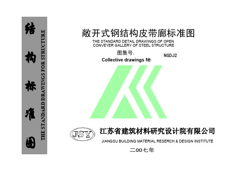
目次附录A(规范性附录)交工技术文件通用表 (7)附录B(规范性附录)交工技术文件土建工程用表 (54)附录C(规范性附录)交工技术文件设备安装工程用表 (68)附录D(规范性附录)交工技术文件管道安装工程用表 (140)附录E(规范性附录)交工技术文件电气安装工程用表 (164)附录F(规范性附录)交工技术文件仪表安装工程用表 (176)附录G(规范性附录)交工技术文件压力容器现场组焊安装工程用表 (188)附录H(规范性附录)交工技术文件起重机械安装工程用表 (202)Appendix A(Normative Appendix)Handover Technical Documentation—General (217)Appendix B(Normative Appendix)Handover Technical Documentation—Civil (264)Appendix C(Normative Appendix)Handover Technical Documentation—Equipment Installation (278)Appendix D(Normative Appendix)Handover Technical Documentation—Piping Installation (351)Appendix E(Normative Appendix)Handover Technical Documentation—Electrical Installation (376)Appendix F(Normative Appendix)Handover Technical Documentation—Instrumentation Installation 388 Appendix G(Normative Appendix)Handover Technical Documentation—Pressure Vessel Site Assembly Welding and Installation (400)Appendix H(Normative Appendix)Handover Technical Documentation—Lifting Machinery Installation (414)IContentsAppendix A(Normative Appendix)Handover Technical Documentation—General (Chinese) (7)Appendix B(Normative Appendix)Handover Technical Documentation—Civil (Chinese) (54)Appendix C(Normative Appendix)Handover Technical Documentation—Equipment Installation (Chinese) (68)Appendix D(Normative Appendix)Handover Technical Documentation—Piping Installation (Chinese) .. 140 Appendix E(Normative Appendix)Handover Technical Documentation—Electrical Installation (Chinese) (164)Appendix F(Normative Appendix)Handover Technical Documentation—Instrumentation Installation (Chinese) (176)Appendix G(Normative Appendix)Handover Technical Documentation—Pressure Vessel Site Assembly Welding and Installation (Chinese) (188)Appendix H(Normative Appendix)Handover Technical Documentation—Lifting Machinery Installation (Chinese) (202)Appendix A(Normative Appendix)Handover Technical Documentation—General (English) (217)Appendix B(Normative Appendix)Handover Technical Documentation—Civil (English) (264)Appendix C(Normative Appendix)Handover Technical Documentation—Equipment Installation (English) (278)Appendix D(Normative Appendix)Handover Technical Documentation—Piping Installation (English) (351)Appendix E(Normative Appendix)Handover Technical Documentation—Electrical Installation (English) (376)Appendix F(Normative Appendix)Handover Technical Documentation—Instrumentation Installation (English) (388)Appendix G(Normative Appendix)Handover Technical Documentation—Pressure Vessel Site Assembly Welding and Installation (English) (400)Appendix H(Normative Appendix)Handover Technical Documentation—Lifting Machinery Installation (English) (414)II附录A(规范性附录)交工技术文件通用表7交工技术文件通用表(续)891011121314附录B(规范性附录)交工技术文件土建工程用表。

清单第1课Site Clearance 场地清理Workmanship 工艺Preambles To Trades 工程量计算原则preamble/ priːˈæmbl / n [C, U] ~ (to sth) opening statement explaining the purpose of the book, document, lecture, etc that follows (书籍﹑文件﹑讲演等的)前言, 序言, 开场白: He launched into his statement without any preamble. 他开门见山地发表言论.清单第2课Site Clearance场地平整,场地清理Wash trough 洗车槽,洗槽,洗涤池,冲洗槽Booster 美['bustɚ]n. 升压机;支持者;扩爆器booster pump增压泵sprinkle 美['sprɪŋkl]n. 撒,洒;少量vt. 洒;微雨;散置vi. 洒,撒;下稀疏小雨;喷sprinkler head喷头,(喷水装置的)喷嘴,stop cock止水阀outfall排水口,出水口run-off channel径流通道hardcore硬底层(碎砖垫层)mesh reinforcement钢筋网UC Beam工字钢梁reinforcement bar Y25 at 75mm centers钢筋中心距crusher run 或 crusher run road碎石道路Consolidate 使固结,巩固,加强consolidated thickness 压实厚度cambers, gradients and crossfalls拱形曲面、坡面、横向放坡camber路拱crown (车道横断面的)路拱顶点crossfall 横向放坡;fall 落差,放坡Gabion(金属笼子)Stonegabion embankment石笼堤坝Gabion石笼,筐、笼:Spillway溢洪道,泄水口:a passage for the extra water from a DAMsediment/ ˈsedɪmənt; ˋsɛdəmənt/ n [U]matter that settles to the bottom of a liquid 沉淀物: a wine with a gritty sediment有沙粒状沉淀物的葡萄酒.matter (eg sand, gravel, mud, etc) carried by water or wind and deposited on the surface of the land 沉积物(如沙﹑砾石﹑泥等).> sedimentary / ˏsedɪˈmentrɪ; ˏsɛdəˋmɛntərɪ/ adj of or like sediment; formed fromsediment (似)沉淀物的; 由沉淀物形成的: sedimentary rocks, eg sandstone, limestone, slate 沉积岩(如砂岩﹑石灰岩﹑板岩).sedimentation / ˏsedɪmenˈteɪʃn; ˏsɛdəmɛnˋteʃən/ n [U] (geology 地质) process ofdepositing sediment 沉淀; 沉积.Basinba·sin /ˈbeɪsən/n[C]:hollow place where water collects (eg a stone structure at the baseof a fountain) 水洼; 水槽; 水池Sediment Basin沉淀池,沉砂池。
工程设计手册总则本手册对门窗幕墙制图标准、设计深度和计算书内容等进行了要求,为了便于采购、降低成本,也对常用的型钢、五金标准件和门窗幕墙附件等制定了选择范围。
1、工作目标1.1 规范化——有效提高门窗幕墙设计制图的工作质量;1.2 标准化——提高门窗幕墙设计制图的工作效率;1.3 网络化——便于网络上规范化管理和成果的共享。
2、工作范围本手册是门窗幕墙CAD 设计制图的统一规则,适用于我司的门窗幕墙的CAD 设计制图及软件开发。
3、工作风格本标准为形成我司绘图表达风格的统一,不提倡个人绘图表达风格。
门窗幕墙设计制图的表达应准确、清晰、完整、美观、统一。
交换文件夹 \0000 设计标准 ( 勿删 !)下。
本手册作为企业设计标准从 2004 年 10 月 1 日起执行,如有与现行国家、 行业和地方标准不符之处,必须执行国家、行业和地方标准。
本手册由深圳市三鑫特种玻璃技术股份有限公司技术中心主编, 全公司各设 计人员若在其具体使用过程中, 发现需要修改或需要补充之处, 请及时将您的有 关意见及资料,提交给技术中心,以便今后对本标准进一步调整和完善。
本手册为第一次修订版。
参加编制人员:张桂先、杨保进、陈立东、谢国生、孙立雄、孙坚、丁鸥、龙才云。
2004 年 9 月 24 日注:本手册电子文档及相关字体、图形文件存放于目录总则1目录2一、制图规定41.1 标题栏41.2图幅41.3图纸排序、图号、图名、工程编号和图框51.4制图比例61.5字体61.6图线61.7尺寸标注71.8符号81.9图纸版本及修改标记91.10图层101.11图纸签名101.12图例11二、设计程序及要求132.1下达设计项目任务书132.2研读工程合同或招标文件132.3查阅建筑设计图132.4方案选择142.6详细施工图或投标图152.7设计方案确认242.8技术交底及文件移交242.9制作观察样板242.10幕墙性能测试样件设计及试验252.11 编制幕墙材料订单252.12 绘制零(组)件加工图262.13 编制加工工艺单、附件单、领料单272.14设计更改272.15绘制工程竣工图样272.16 统计工程竣工面积272.17设计资料归档272.18各种图纸应表述的内容282.19其它有关规定28三、常用材料的技术参数303.1铝合金型材的强度设计值303.2单层铝合金板的强度设计值303.3铝塑复合板的强度设计值313.4蜂窝铝板的强度设计值313.5不锈钢板的强度设计值313.6钢材的强度设计值313.8铝包钢铰线的计算参数333.9 不锈钢(304或316)钢绞线技术参数表333.10幕墙材料的弹性模量343.11幕墙材料的泊松比343.12幕墙材料线膨胀系数353.13幕墙材料的重力密度35四、常用材料的规格表364.1硅酮结构密封胶产品选用规定364.2常用型钢、五金标准件、附件选用表39五、相关的国家及行业标准515.1 .建筑及结构设计规范515.2.幕墙工程技术规范525.3 .幕墙性能检测方法525.4. 幕墙材料标准535.5. 五金件54六、常用参考书目55七、附表与附图56、制图规定1.1 标题栏1.1.1 常用图纸格式见附图一、二、三、四、五。
Sample Punch ListThis document is provided primarily for landscape contractors who have not previously worked with Garth and would like to know what issues are frequently addressed by site observation visits during construction. The letter shows many possible deficiencies and is much longer than normal.I visited the site on Tuesday to determine whether the landscape work was substantially complete and ready for the start of the 60 day maintenance period. My observations and comments follow:I.ROUGH GRADINGA.Planter Soil1.The planter soil in one planter (see the attached “Landscape Corrections”sheet) does not appear to meet the 24" minimum depth specified inSection 02920, Part 3 “Compacted Planting Areas”. The planter must beexcavated and backfilled with approved planting soil.2.Some of the planter soil contains unacceptable amounts of large rocksand debris. Remove all rocks larger than 2 inches which are visible on thesoil surface. See Specification Section 02920, Part 3 “Soil Preparation”.B.Drainage1.The drain inlet north of the building entry is set too high for adequatelandscape drainage and must be lowered.2.The flow line of the vegetated swale does not slope consistently towardthe drain inlet. The swale must be re-graded to provide positive drainage. II.IRRIGATIONA.Point of Connection1.The filter and pressure regulator must be installed per Detail A, Sheet L1.2.Install the specified fertilizer injector per Detail B, Sheet L1.B.Controller1.Install 110v wiring in conduit with a duplex box (with a switch) in accordwith Detail C, Sheet L1.2.Connect the remote control valves to the controller in the sequenceshown on the Irrigation Plan.3.The rain switch must be installed as indicated on the Plan.C.The quick coupling valves must have gravel placed in the bottom of the boxesper Detail A, Sheet L3.D.Remote Control Valves1.Install ball valve cut-offs upstream of the valves in accord with Detail B,Sheet L3. This allows the remote control valve to be serviced withoutshutting down and draining the mainline.2.Pressure regulators must be installed on all the drip valves as indicated inthe Irrigation Legend, Sheet L1.3.No gravel was placed in the bottom of the valve boxes. Install gravelunder the valves to a depth of 3 inches in accordance with Detail B, SheetL3.4.The foundation bricks under the valve box were omitted. The bricksprevent settling of the valve box over time and must be installed.5.Valve station tags must be installed. See Specification Section 02810,Parts 2 and 3 “Valves”.6.Install a 6' length of hose on the flush ends of all filters per Detail C, SheetL3.E.Rotor Heads1.Adjust the arcs and throws of rotors to prevent over-spray onto pavementand structures.2.Check valves are required in several areas to prevent low head drainage.See Specification Section 02810, Part 3 “Sprinkler Heads”.F.Spray Heads1.Variable Arc Nozzles (VAN’s) were installed on many of the sprinklerswhere fixed arc nozzles would have been appropriate. VAN’s use about50% more water than fixed arc nozzles and the spray pattern is lessconsistent. Replace all VAN’s where fixed nozzles would conform to thenecessary arc.2.Pressure regulating heads were not installed as indicated on the IrrigationLegend. With the high pressures found on-site, this results in nozzle“fogging” which can severely reduce irrigation efficiency, particularlyduring windy conditions. The specified heads must be installed.3.Pop-up sprinkler heights were not consistent with the Plan. All 6 inchpop-ups must be replaced where 12 inch pop-ups are specified.4.Several spray heads shown on the Plan were missing and must beadded. See the attached “Landscape Corrections” sheet.5.Adjust spray heads to proper height above finish grade per Detail I, SheetL3.6.Several nozzles need to be turned down to minimize over-spray ontopavement and structures.G.Subsurface Drip Irrigation1.Drip Tubinga.The installed drip tubing was not the specified Toro DL 2000 tube.The Toro tubing is treated with an herbicide that has been found toprevent root intrusion into the underground emitters. The installedproduct does not have this protection and has been shown to bevulnerable to blockage due to root intrusion and is therefore notacceptable. All the drip tubing on the site must be as specified.b.The spacing of tubing exceeded the 21" minimum shown on thePlan. Re-space tubing as required to meet the minimum spacing.c.The distance between the tubing and edge of the planter exceedsthe 4-6 inches indicated in Specification Section 02810, Part 3“Drip Irrigation”. The heat absorbed by adjacent pavement driesthe soil faster than interior portions of the planter. Relocate tubingto the specified location.d.The manifold connecting the supply lateral and the drip tubing wasnot installed with a flexible p.v.c. riser in accord with the “Drip Riser”Detail. No rigid pipe can occur within 12 inches of finish grade indrip irrigated areas.2.Air Relief Valves (see Detail G, Sheet L3)a.Install in all the drip planters per Plan. These valves allow air intothe drip tubing as water drains through the emitters while thesystem shuts down. Without the air relief valve, air is suckedthrough the higher emitters, potentially drawing debris into thetubing.b.Air relief valves must have gravel placed in the bottom of the boxes.3.Flush Valves (see Detail H, Sheet L3)a. A 3' depth, geotextile lined sump is required for all flush valves.b.Attach a 2' length of p.v.c. flex hose to the flush end and coil in thevalve box. The hose allows for manual flushing without flooding thebox.c.Valve boxes for flush valves must be 12 inches in diameter (thisallows the flush hose to be coiled without kinking).III.PLANTINGA.Soil Preparation: Soil additives were scattered over the soil surface and werenot adequately tilled in. All additives must be tilled into the soil to a depth of 6inches per Specification Section 02920, Part 3.B.Finish Grading1. A 2% minimum slope must be maintained away from structures (seeSpecification Section 02920, Part 3 “Finish Grading”).2.The finish grade must be adjusted to 1 inch below adjacent pavement.C.Weed kill operations do not appear to have occurred before planting.Specification Section 02920, Part 3 “Weed Kill” calls for a 14 day, irrigated weedgermination period followed by application of a non-selective herbicide. Thisprocedure can drastically reduce future weed related maintenance and must beimplemented.D.Trees (see Detail A, Sheet L2)1.Trees in turf areas must have a 3 foot diameter circle cleared andmulched around the trunks.2.The trunk and branch structure of the Zelkova tree northwest of thebuilding is unsatisfactory and the tree must be replaced. Tree branchingmust be in accord with Specification Section 02950, Part 2 “PlantMaterials”.3.The roots on 2 of the London Plane Trees are badly kinked near the rootcrown and indicate a potential for future problems. These trees must bereplaced (see the attached “Landscape Corrections” sheet). Tree rootballs must conform with the criteria of Specification Section 02950, Part 2“Plant Materials”.4.Stakinga.Nursery stakes were left on the trees. These stakes can actuallyweaken the trunk over time and scar bark. All nursery stakes mustbe removed. Trees with small calipers which will not stand erectwithout nursery stakes may have additional pairs of tree ties addedlower on the trunk. Trees with too much height or too little caliper tobe supported by the specified staking system should be replaced.b.The tree stakes were loose and do not provide support. The stakesshould be a minimum of 10 feet in length when installed and bedriven into the undisturbed native soil to a minimum depth of 6inches.c.Tree stakes protruded well beyond the highest ties. Stake topsshould be cut off 2 inches above the highest tree tie.E.Shrubs and Groundcover1.The health of some of the shrubs did not appear to be satisfactory. Allshrubs which are dead or in a state of decline must be replaced promptly.See Specification Section 02970, Part 3 “Trees, Shrubs andGroundcover” and the attached “Landscape Corrections” sheet.2.Some discrepancies between shrub quantities on the Plan and in the fieldwere noted. These discrepancies are noted on the “LandscapeCorrections” sheet attached. Verify my field counts prior to orderingplants. Install the specified plants in the quantity delineated on thePlanting Plan.F.Top dressing depths were often found to be less than the 2 inch minimumspecified in Section 02950, Part 3 “Top Dressing”. Top dressing should beadded as necessary to meet the minimum depth.G.Erosion Control1.Jute netting was substituted for the specified North American Greenblanket. The installed netting is intended for short term use onconstruction sites and therefore is not equal to the two year life-span ofthe specified blanket (which contains slow degrading coconut fibers). Thespecified blanket must be installed throughout the site.2.Erosion control blankets must be installed on all areas planted with Carex(bio-swales) and all slopes steeper than 4:1 as specified in Note 5, SheetL2 and in Section 02950, Parts 2 and 3 “Erosion Control Blanket”.H.Weeding1.Weeds were noted in moderate quantities in some shrub areas. Allweeds must be removed.2.Many turf areas contained unacceptable densities of weeds. Spray turfwith a selective herbicide or hand pull weeds in accord with SpecificationSection 02970, Part 3 “Turf”.I.Significant amounts of litter were present in the planters. Section 02970, Part 3“Trash Removal” requires the removal of litter from planters every 7 days untilFinal Acceptance.The landscape work is substantially complete, in my opinion. I recommend that the 60 day maintenance period be authorized to commence as of the day of the walk-through providing that the items above are completed within 10 working days.At the close of the maintenance period, the Landscape Contractor must deliver the items noted in Specification Section 02810, Part 1 "Submittals” and the plant guarantee form found at the end of Specification Section 02970, to the Owner’s Representative.Please call me if you have any questions or concerns.Best regards,Garth RuffnerLandscape Architect #2808。
1 J007-1~2 道路(1993 年合订本)2 J007-3~4 道路(1993 年合订本)3 J007-5~8 道路(1993 年合订本)4 04J008 挡土墙(重力式、衡重式、悬臂式)5 03J012-2 环境景观-绿化种植设计6 04J012-3 环境景观-亭、廊、架之一7 10J012-4 环境景观-滨水工程8 12J003 室外工程9 15J012-1 环境景观—室外工程细部构造10 15J001 围墙大门39.572.560.357372255799679原 93SJ007(一)、 (二)改号合订原 93SJ007(三)、 (四)改号合订原 93SJ007(五)~(八)改号合订代替 95J008-1、00J008-2~3含光盘替代 02J003替代 03J012-11 2 3 4 5 6 7 8 9 10 11 12 13 141 2 04J114-205J102-107J103-806J10606J12310J12110J113-111J122J111~11413J10414J10513J103-716J107、16G61715J101 15G61203J20306J204石膏砌块内隔墙混凝土小型空心砌块墙体建造构造双层幕墙挡雨板及栈台雨篷墙体节能建造构造外墙外保温建造构造内隔墙-轻质条板(一)外墙内保温建造构造内隔墙建造构造(2022 年合订本)蒸压加气混凝土砌块、板材构造烧结页岩多孔砖、砌块墙体建造构造人造板材幕墙夹心保温墙建造与结构构造砖墙建造结构构造平屋面改坡屋面建造构造屋面节能建造构造1723261730585949129824783482920修编代替 J101-1~2(2002 年合订本)替代 02J121-1、99J121-2、99(03)J121-2、06J121-3替代 03J113替代 03J122替代 07J107、07SG617替代 04J101、04G6123 4 5 6 71 2 3 4 5 6 71 2 3 41 2 3 4 5 6 7 8 9 1007J20509J202-112J20114J20615J207-106J30507J30608J333J331、J332 G22108J332 08G22110J30112J30413J40413CJ40-115J403-115J40102J503-106J505-103J501-2、03G37207J501-107SJ504-111J50812J502-213J502-113J502-316J509玻璃采光顶坡屋面建造构造(一)平屋面建造构造种植屋面建造构造单层防水卷材屋面建造构造(一) --金属屋面重载地面、轨道等特殊楼地面窗井、设备吊装口、排水沟、集水坑建造防腐蚀构造地沟及盖板(2022 合订本)砌体地沟地下建造防水构造楼地面建造构造建造防水系统构造(一) (参考图集)楼梯栏杆栏板(一)钢梯常用建造色外装修(一)钢筋混凝土雨篷(建造、结构合订本)钢雨篷(一)-玻璃面板隔断隔断墙(一)建造玻璃应用构造-栏板隔断地板吊顶水下玻璃挡烟垂壁内装修-室内吊顶内装修-墙面装修内装修—楼(地)面装修铝合金护栏58626958662327654512388928989836656527586689786587替代 00J202-1、00(03)J202-1、01J202-2替代 99J201-1、99(03)J201-1、03J201-2。
Punch List Shougang
Reference Picture
Page1of 7
Reference picture PL 01
Reference picture PL 01: temporary transportation and lifting devices not removed
Reference picture PL 03
Reference picture PL 03: Incomplete installation of clamping device Drawing 47.30.01-01
Reference picture PL 03: The stopper plates of the stationary hood clamps are only tack welded. (Full weld is
required)Draw no. 47.30.01
Reference picture PL 03: The supports of all lifting and guiding devices of the stationary hood are not welded to
the upper reinforcement ring (Flange ring)
Punch List Shougang
Reference Picture
Page2of 7
Reference picture PL 04
Reference picture PL 04: Stationary hood and movable hood are not aligned. Gap atguiding bolts is about 15mm.
Draw no 10.50.71-01
Reference picture PL 05
Reference picture PL 05 Missing refractorymaterial
Reference picture PL 06
Reference picture PL 06: Heat protection boxes for the skirt supports are partly not yetinstalled
Punch List Shougang
Reference Picture
Page3of 7
Reference picture PL 08
OSCHATZdesignDrawing 95.00.00-01
Cerisdesign
Reference picture PL 08: Design change of flexible lines restricts lifting and lowering of skirt
Reference picture PL 09
Reference picture PL 09: Interfrence betweendrilling machine unit (cleaning unit)Drawing 10.06.51-01and piping
Reference picture PL 10
Reference picture PL 10: All fourguiding bolts of the main support of the movable hood are not welded.
Drawing10.08.52-01
Punch List Shougang
Reference Picture
Page4of 7
Reference picture PL 11
Reference picture PL 11: Support welded directely totheSteel structure,Piping of the Moveble hood can not
follow during transfer action
Reference picture PL 11: Moveble hood restricted from transferto parkingposition,as drain can’t pass the
support of the fixed hood
Reference picture PL 13
Reference picture PL 13: Pendulum support requieres fully weld all around the base plates.Draw no. 41.20.10-01
Travell directionpark position
Travel direction
Punch List Shougang
Reference Picture
Page5of 7
Reference picture PL 15
Reference picture PL 15: Pneumatic cylinders are not adjusted for the movements. (Stroke of cylinders) Draw no.
10.05.10-01
Reference picture PL 17
Reference picture PL 17: Improper installation of Steam Drum Support (Saddles)
Reference picture PL 20
Reference picture PL 20: Improper support of pump suction screens / Restricted access for dismantling /
raplacement of internal screens
Punch List Shougang
Reference Picture
Page6of 7
Reference picture PL 21
Reference picture PL 21: Damaged drain pipe of the distributor of the deflection bend.
Reference picture PL 22
Reference picture PL22: Piping reassembledwithout removal of debrisfrom oxyfuel cutting
Reference picture PL 24
Reference picture PL 24: Routing of piping, insufficient support
Reference Picture 24:
To close distance of piping and instrumentationInsufficient space for insulation
Punch List Shougang
Reference Picture
Page7of 7
Reference picture PL 29
Reference picture PL 29: Pipe supports welded between two reinforcementrings