CTC瑞斯康达协议转换器
- 格式:pdf
- 大小:389.23 KB
- 文档页数:44

瑞斯康达边缘接入网综合网管解决方案【简介】NView NNM系统针对解决边缘接入网运营维护的问题,遵循ITU-T M.3010标准规范,采用TCP/IP和SNMP协议,并采用面向服务的应用集成架构的设计方法...边缘接入网通常意义下指由用户侧到运营商机房这一网络层面。
随着互联网内容的不断丰富,网络电子交易、网络游戏、网络视频、VOD等网络应用的日益普及,网络带宽的需求空间迅速膨胀,边缘接入网得到了快速发展,与此同时对边缘接入网的可靠性和可维护性的新需求也不断涌现,这样对网络配置、监控和维护的平台——网络管理系统提出了更高的标准要求。
针对宽带接入设备品种多、分布广、数量大、管理和监控困难的特点,瑞斯康达科技凭借自身在网络管理软件开发方面的多年经验和对客户网管需求的良好理解,推出全新的边缘接入网综合网管整体解决方案——NView NNM。
边缘接入网运维难题1.分布广,数量庞大,管理层次复杂边缘接入网设备节点分布密集程度非常高,数量极其庞大,IP地址资源耗费严重,网络拓扑层次多,运维管理体制面临边缘接入网的这个特点,采用传统网管系统的“平面集中”管理体制已经很难适应。
2.接入设备品种多样化边缘接入网技术发展迅速,除了传统的LAN、xDSL、HFC等技术,也涌现出了许多新技术,例如FTTH、无线热点接入等,并且许多核心网的技术手段被应用到网络边缘以提高网络的带宽和可靠性。
网络运营商的接入网建设根据自身的资源特点采用不同的技术手段,这就造成边缘接入网的设备品种的多样化。
然而运营商目前采用不同类型设备的网管系统,只能针对某种类型的设备进行管理,无法管理整个网络,同时也造成了各个信息孤岛,系统难于融合。
3.与现有OSS系统整合困难边缘接入网管理归根结底还是设备节点的管理,然而传统管理模式下,品种多样化造成的设备节点管理系统繁多,一个中心机房可能会存在许多套管理系统,一方面对网络没有统一的全局的管理视图;另一方面,很难与现有的OSS系统整合,建设新的OSS系统同样面临设备接口复杂,数据模型不一致,要开发大量的接口转换模块,使OSS系统开发周期长,人力物力投入大。


RC903-V35FE1 V.35至成帧E1接口转换器使用手册(免费下载)北京瑞斯康达科技发展有限公司目录第一章RC903-V35FE1(B版)概述 (3)第二章连接配置 (5)第四章安装与准备工作 (8)第四章开关设置说明 (9)第五章常见故障解答 (13)第一章 RC903-V35FE1(B版)概述一、产品描述RC903-V35FE1是北京瑞斯康达科技发展有限公司出品的V.35转单路透明E1台式接口转换器,适用于V.35设备基于E1网络传输的接口转换器,或称介质转换器。
随着E1线路资源的不断丰富,各种利用E1线路资源用于数据传输的方案被用户普遍接受。
RC903-V35FE1为独立的台式转换器,单独供电,放置与桌面上。
二、产品参数1、E1接口技术指标输入阻抗:75Ω(非平衡BNC接口)、120Ω(平衡RJ-45接口)接口速率:2048Kbps±50ppm编码类型: HDB3电气特性:符合ITU-T G.703建议帧结构:符合ITU-T G.704建议抖动容限:符合ITU-T G.823建议功能特性:完备的线路告警指示、故障转移,及智能自动复位功能2、V.35接口技术指标物理特性:符合V.35接口标准接口类型:ISO 2593阴性连接器(34针母口)工作方式:DCE接口速率:E1成帧模式时,V.35接口速率N×64Kbps(N=1~31)E1透明模式时,V.35接口速率2048kbps三、前面板及指示灯意义其中各指示灯表示接口转换器状态如下:电源指示灯(PWR):常亮,电源工作正常;反之错误链路中断告警(LOS):常灭,E1链路接收有信号;反之E1信号丢失链路错误告警(LER):常亮,本端E1接收信号错误时(包括上游E1链路告警AIS、E1帧失步告警LOF、CRC4校验错);常灭,正常远端设备告警(RAL):常亮,远端转换器有LOS或者LER告警远端环回测试(RLP):常亮,远端E1处于环回状态其中各接口定义如下:E1接口定义如下:TX:BNC座,75欧姆非平衡接口,E1信号输出RX:BNC座,75欧姆非平衡接口,E1信号输入BALANCE:RJ-45座,120欧姆平衡接口,1、2芯输出,5、6芯输入。


RC905-EE1以太网至单路E1接口转换器使用手册北京瑞斯康达科技发展有限公司2004年7月目录第一章概述 (3)第二章使用方法 (3)一、设备面板介绍: (3)二、基本指标: (5)三、设置开关说明: (6)四、转发数据在成帧E1帧格式中的占用 (10)第三章设备的连接 (10)第四章常见故障解答 (12)第一章概述REV.B改版说明:1.更改底面设置开关SW2的第1位、第2位、第3位的定义,请老版本用户特别注意!2.新增以太网端口双工自协商能力,可直接连接交换机的自适应端口;3.新增以太网端口自动交叉反线识别能力,使工程人员不受网线线序的捆饶4.新增以太网端口半双工模式时的back pressure流量控制能力;5.新增抗广播风暴能力。
特别说明:RC905-EE1(REV.B)可与老版本REV.A互通,但需注意SW2第1、3位的定义有所改变,如有问题可电话咨询我公司技术人员。
本设备不能与RC901-EE1、RC902-EE1转换器对通。
主要特点:●提供1路10BaseT以太网RJ45端口和1组E1(75欧姆BNC和120欧姆RJ45)端口,实现以太网数据在E1通道中的传输●可以在E1成帧和E1透明两种工作模式下选择,并且在成帧工作模式下可以设置E1的使用带宽,转发速率为N×64Kbps(N=1~32)●E1成帧模式时,具有远端控制功能,可以控制远端设备的E1环回;并且可以查询到远端告警信息●支持最大以太网数据帧长1593字节●支持以太网端口半双工/全双工自动协商能力●支持以太网端口全双工模式下IEEE 802.3x流量控制●支持以太网端口半双工模式下back pressure流量控制第二章使用方法一、设备面板介绍:● 其中各指示灯定义如下:E1线路指示包括:LOS (红色):E1链路接收信号丢失告警,E1线路正常工作时,灭。
LER (红色):E1链路接收信号错误告警。
在E1成帧模式下,该告警表示接收信号有LOF (信号帧失步),或AIS (上游E1告警),或CRC (成帧E1的CRC4校验错误);在E1透明模式(非成帧)下,该告警只表示AIS (上游E1告警)。

常用设备综合测试(PDH、光收、协转、单板)一、设备指示灯及常识部分:1.PDH格林威尔EE1000,光接口波长:1310nm(标准机型)/1550nm发送功率:>-14dBm接收灵敏度:优于-32dBm(误码率≤10 ) ;格林威尔EE1500发送功率:优于-13dBm,接收灵敏度:优于-34dBm(误码率≤10-11。
其无中继传输距离大于30km。
E1接口符合ITU-T G.703建议, 速率为:2048Kbit/s;码型:HDB3;阻抗:75Ω/非平衡,120Ω/平衡;抖动特性:满足ITU-T G.742、ITU-T G.823建议,输入口允许衰减:0~6dB。
2.PDH设备前面板告警状态指示灯含义:RUN灯,含义:运行灯,绿色均匀闪烁表示:CPU 运行正常;ALM灯含义:总告警,红色长亮表示,本端设备光纤、E1接口检测到告警;RA 灯含义:对端告警灯,黄灯长亮,表示:当对端设备有任何告警(不包含以太网告警);OPL灯含义:收无光告警灯,红灯亮时表示:对端设备故障或光纤断裂造成无光信号输入;LOF灯含义:失步告警灯,红灯亮时表示:发生光口帧失步;RMA灯含义:对端告警指示灯,当对端设备光接口、E1接口有任何告警状态时,该灯状态为:红色长亮。
OIA灯含义:光接口A工作状态指示灯;工作正常时,该指示灯显示绿色长亮;光接口A检测到LOS 或LOF告警时,该指示灯显示:红色长亮;当光接口A检测到1E-3或1E-6误码时,该指示灯显示:黄色长亮。
3.常用瑞斯康达双纤光纤收发器型号有:RC111-FE(A)-S1和RC112-FE(A)-S1,工作波长为:1310nm;发射功率为:-13~-3dBm;接收灵敏度为:-35dBm;估计传输距离约为:0~25Km,单纤型号有:RC315-FE(A)-S1和RC316-FE(A)-S1,并需要成对使用。
4.光纤收发器指示灯:光口部分:RLK表示:光接收链路灯,常亮表示,光口接收链路正常;不亮表示,接收链路错误;TLK表示:光发送链路灯,常亮表示,光口发送链路正常;不亮且RLK亮表示,发送链路错误;ACT表示:光数据收发灯,闪亮表示:光口有数据传输。


协议转换器,简称协转介绍1. 定义:完成协议转换功能的设备。
2. 协议转换器,简称协转,也叫接⼝转换器,协议转换器也就是⽹关,它能使处于通信⽹上采⽤不同⾼层协议的主机仍然互相合作,完成各种分布式应⽤。
3. 它⼯作在传输层或更⾼。
接⼝协议转换器⼀般⽤⼀个ASIC芯⽚就可以完成,成本低,体积⼩。
它可以将IEEE802.3协议以太⽹或V.35数据接⼝同标准G.703协议的2M接⼝之间进⾏相互转换。
4. 它将以太⽹信号或V.35信号转换为E1信号,以E1信号形式在同步/准同步数字⽹上进⾏长距离传输。
其主要⽬的是为了延长以太⽹信号和V.35信号的传输距离,是⼀种⽹络接⼊设备。
5. 现有的协议转换器主要分为E1/以太⽹系列和E1/V.35系列。
6. 协议转换器⽤于构架⽹络连接,将⼀种协议转换为另⼀种协议。
CPOS和E1应⽤1. CPOS(155M)可划分为61个E1(2M),⼀般分公司或银⾏跨省之间使⽤CPOS接CPOS。
2. E1可划分为30个时隙(64K),⼀般划分为是2的倍数,如1、2、4、8个。
这种应⽤现在⽐较少。
3. SDH:运营商―――(传输介质:光纤)——————设备:光纤终端机(简称光端机)——————(传输介质:电缆[70欧]或120欧平衡线)————设备:协转[DCE]————(传输介质:V.35)————设备:路由器[DTE]——————设备:核⼼交换机4. 其它⼀种:协转和路由器被替换成:配E1模块的路由器5. DCE:传输设备。
DTE:终端设备。
G703 10000—U协转介绍1. 运⾏模式:(1)NORMAL:正常模式。
(2)DATA PORT:DB23内部的收和发串起来。
(3)G.703/G.704:电缆内部和收和发串起来,RJ45的收和发也打环。
2. 跳线:(1) 1:120欧代表是⽹⼝线,70欧代表是电缆线。
(2) 2:(3) 3、4、5、6、7:代表帧格式、长度等,两边⼀致即可。
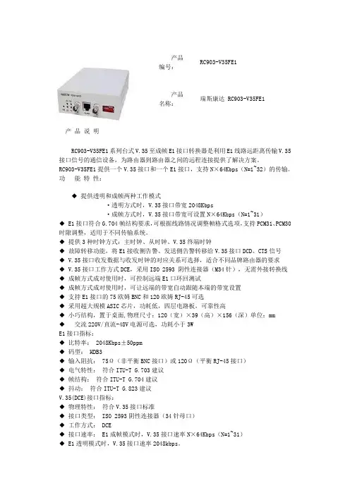
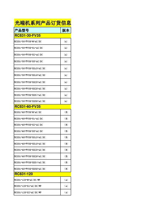
产品编号:RC903-V35FE1产品名称:瑞斯康达 RC903-V35FE1 产品说明RC903-V35FE1系列台式V.35至成帧E1接口转换器是利用E1线路远距离传输V.35接口信号的通信设备,为路由器到路由器之间的远程连接提供了解决方案。
RC903-V35FE1提供一个V.35接口和一个E1接口,支持N×64Kbps(N=1~32)的传输。
功能特性:◆提供透明和成帧两种工作模式·透明方式时,V.35接口带宽2048Kbps·成帧方式时,V.35接口带宽可设置N×64Kbps(N=1~31)◆ E1接口符合G.704帧结构要求,可根据线路情况调整帧格式选项,支持PCM31、PCM30时隙调整,适用于不同传输系统。
◆提供3种时钟方式:主时钟、从时钟、V.35终端时钟◆故障转移功能,将E1接收侧告警、发送侧告警转移给V.35接口DCD、CTS信号◆ V.35接口收发数据与收发时钟的对应关系可选择,适合不同品牌路由器的要求◆ V.35接口工作方式DCE,采用ISO 2593 阴性连接器(M34针),无需外接转换线◆成帧方式成对使用时,可控制远端E1口环回测试◆成帧方式成对使用时,可让远端的带宽自动跟随本端的带宽设置◆支持E1接口的75欧姆BNC和120欧姆RJ-45可选◆采用超大规模ASIC芯片,功耗低,四层电路板,可靠性高◆小巧结构,置于桌面,物理尺寸:120(宽)×39(高)×156(深)单位:mm◆交流220V/直流-48V电源可选,功耗小于3WE1接口指标:◆比特率:2048Kbps±50ppm◆码型: HDB3◆输入阻抗: 75Ω(非平衡BNC接口)或120Ω(平衡RJ-45接口)◆电气特性:符合ITU-T G.703建议◆帧结构:符合ITU-T G.704建议◆抖动:符合ITU-T G.823建议V.35(DCE)接口指标:◆物理特性:符合V.35接口标准◆接口类型: ISO 2593阴性连接器(34针母口)◆工作方式: DCE◆接口速率: E1成帧模式时,V.35接口速率N×64Kbps(N=1~31)◆ E1透明模式时,V.35接口速率2048kbps。
OPCOM3500E MSAP综合业务接入平台产品概述OPCOM3500E 综合业务接入平台(MSAP)是面向传统TDM业务和宽带IP数据业务接入的汇聚型设备,定位于城域网接入层。
OPCOM3500E在线路侧实现SDH 155M上行,用户侧提供SDH、PDH、以太等各种接入方式,OPCOM3500E能够满足运营商大客户接入、3G和NGN网接入层的各类需求。
OPCOM3500E在上行方向利用155M光口替代大量传统PDH设备的E1电口,解决E1连接线缆过多而带来故障点多、维护成本高的问题;在用户方向可将E1、V35、以太网等业务转化成VC12进行汇聚收敛和统一调度,为方便灵活的进行业务配置,提高业务开通效率创造了条件;通过高密度集成,减少局端PDH、协转、光纤收发器等设备机房空间的占用成本;OPCOM3500E将SDH完善的OAM管理功能和瑞斯康达独特的远端网管RC.LINK技术相结合,实现对接入层设备的全程网管,提高运营商对接入层网络的管理控制能力。
功能特点1.基于电信级的产品设计,线路侧最大可提供4路STM-1光口或两路STM-4,支持群路盘1+1备份,实现群路、交叉和时钟模块的热备份;双电源热备份和负荷分担;支持支路盘的1+1保护;采用SFP热插拔光接口及板卡全面热插拔设计;2.单个子框最大支持160路E1或80路以太网接入;3.可与Raisecom以太网光纤收发器、PDH光端机、以太网复用器、协议转换器、PCM、SDH多业务光端机等产品实现互通和远端网管;支持内置DCN网管通道,解决运营商DCN网对接入层覆盖不足的问题;支持多个子框的网管级联;4.提供内置误码仪功能和远端设备掉电告警功能,提供机箱告警输出,支持网管平台对本地设备板卡和远端设备的软件在线升级功能;5.支持SDH通道和复用段保护,可实现多种网络拓扑,包括点到点、链型、环型和环带链等;6.支持EOS功能,采用GFP、LAPS封装协议,支持LCAS功能,可与主流MSTP厂商设备兼容对通。
协议转换器指示灯表示2010-04-08 16:04:44| 分类:计算机知识|字号大中小订阅协议转换器分成GE和GV两种。
简单的说,GE就是将2M转换成RJ45的以太网接口;GV就是将2M转换成V35接口,以便与路由器相接。
一.瑞斯康达公司的RC系列有GE和GV两种。
一般工作中用到GE系列的RC905,RC906公司已经停产,现在就生产RC952。
GV系列的有RC903,RC903按照其主板又分成B版和C版两种,通过拨码,B版和C版可以相互替换使用。
1.RC952-FEE1(GE系列指示灯含义基本一样)a.E1线路指示LOS(红色):本地E1接收信号丢失告警,LOS-红常亮无LOS-灭LER(双色):本地其余告警:AIS-红闪亮LOF-黄常亮CRC-黄闪亮无告警是此灯灭RLP(双色):远端环回及误码仪测试指示灯远端环回测试时:环回不成功-黄闪亮环回成功-黄长亮误码仪测试时:有误码-绿闪亮无误码-绿常亮正常情况-灭RAL(双色):远端设备的E1链路告警LOS-红闪亮AIS-红闪亮LOF-黄常亮CRC-黄闪亮无告警-灭以上告警定义如下:LOS:E1接收信号丢失AIS:E1收到全1数据,一般是上游设备出现故障的表现LOF:E1成帧时表示帧失步,E1透明时表示收到非法帧CRC:E1成帧时表示E1 CRC告警,E1透明时表示HDLC CRC告警b.以太网指示LINK/ACT(绿色):网线连接正常时,常亮;数据收发时,闪烁100M(黄色):100M常亮;10M灭FDX(绿色):全双工,常亮;半双工时灭;有冲突时该灯闪烁c.RC-952的电路板背面(元器件少的一面)有5个8位开关SW1~SW5,正面(元器件多的一面)有一个4位开关SW6。
SW1开关表示:位号功能说明1 以太网接口自适应开关ON关闭自适应,OFF开启自适应2 10M/100M开关ON 10M ,OFF 100M3 全双/半双开关ON 半双工,OFF 全双工4 故障转移功能开关ON打开故障转移功能OFF关闭此功能5 设备主从选择开关ON从模式OFF主模式6 时钟模式选择开关ON从时钟OFF主时钟7 环回使能开关ON环回OFF不环回8 环回位置开关ON本地环回OFF远端环回SW1的8位开关默认全为OFFSW2~SW5开关表示SW2的第1位:ON=E1成帧模式,此时速率为N*64Kbps,N=1~31OFF=E1透明模式,也称非成帧模式,此时速率为2048Kbps(默认状态)在默认状态下,SW2的2-8位,SW3-SW5的1-8全部无效,只有本位拨至成帧模式,这些开关才有效SW2的2-8,SW3-SW5的1-8:E1时隙占用开关,ON=占用OFF=不占用,此31位开关依次对应时隙1-31,用户设置了成帧模式后,需通过此31位开关进行时隙选择。
RC952-FEE1 模块式协议转换器产品简述:RC952-FEE1是单路10/100M自适应以太网口到单路E1的EoPDH转换设备。
该设备可以点到点成对组网,也支持同系列设备的无缝对通和统一网管。
RC952-FEE1协议转换器模块可安装于瑞斯康达专用3U十六槽机箱或四槽机箱中使用,实现SNMP网管;也可配合专用单槽小机箱作为桌面式设备使用,并可作为远端设备与局端设备一起实现远端网管。
功能特点:➢支持E1成帧/透明模式下的带内远端网管。
➢透明模式下可管理到本端/远端协转和末端收发器。
➢E1成帧模式下,可透过DXC/PCM设备的进行远端网管。
➢E1成帧模式下,支持任意时隙指定,并具有E1 CRC校验自动检测能力。
➢强大的兼容性,可与其它厂家以太转E1协议转换器互通。
➢具有E1线路故障转移功能,将E1接收侧告警,发送侧告警转移到以太网口。
➢支持透明/成帧模式下的远端环回测试,并具有E1链路误码仪的功能。
➢内建32M超大缓存,缓解突发冲击。
产品技术参数:产品属性➢提供1个10/100BaseT以太网电口和1路E1端口。
➢提供E1成帧和E1透明两种工作模式:透明模式下, E1 接口带宽2048Kbps ➢成帧模式下, E1接口带宽可设置N*64Kbps(N=1~31) 且每一时隙均独立可选。
➢提供两种时钟方式:主时钟(内部时钟),从时钟(E1接收恢复时钟)。
➢提供丰富的告警信息,具有E1线路故障分析告警功能,可轻松判断故障点。
➢支持以太网端口流量控制。
➢安装在RC系列1槽,4槽,16槽机箱内,采用机箱统一供电。
➢设备功耗小于3W。
E1接口指标比特率: 2048Kbps±50ppm。
码型: HDB3 。
输入阻抗: 75Ω(非平衡BNC接口)或120Ω(平衡)。
电气特性:符合ITU-T G.703建议。
帧结构:符合ITU-T G.704建议。
抖动:符合ITU-T G.823建议。
以太网接口指标符合IEEE 802.3 Ethernet相关标准。
USER MANUAL EOe-110/100Base Ethernet over G.703 Unframed E1CTC Union Technologies Co., Ltd.Far Eastern Vienna BuildingNeihu Technology Park8F, No. 60 ZhouZi St.Neihu, Taipei, 114TaiwanEOe-1 Ethernet over E1, User ManualVersion 1.0 October 2003 First PrintingVersion 1.01 October 2004 Second PrintingThis manual supports the following models: EOe-1 Ethernet over E1Specifications subject to change without notice.Table of ContentsChapter 1. Introduction (1)1.1 General (1)1.2 Technical Specifications (2)1.3 E1 Signal Structure (6)1.4 EOe-1 Capabilities (7)1.5 System Timing Considerations (8)1.6 Functional Description (10)1.7 Typical System Applications (11)Chapter 2. Installation (13)2.1 General (13)2.2 Site Preparations (13)2.3 Mechanical Assembly (13)2.4 Electrical Installation (13)2.5 DIP Switches and Jumper Settings (16)2.6 Rack Mount Installation (18)Chapter 3. Operation (21)3.1 General (21)3.2 Controls and Indicators (21)3.3 Operating Procedure (23)Chapter 4. Test & Diagnostics (25)4.1 General (25)4.2 Loop Back Tests (25)4.3 Bit Error Rate Tester (25)4.4 Local Loop Back (27)4.5 Remote Loop Back (28)iTable of ContentsAppendix A. DIP SW Setting EOe-1 (31)A.1 DIP SW1 Bridge, Ethernet and WAN Speed (31)A.2 DIP SW2 Memory Config and E1 Settings (32)Appendix B. Interface Connections (33)B.1 E1 Line Connectors (33)B.2 E1 Line Frame Ground (34)B.3 Ethernet RJ-45 Connector (34)Technical Inquiry FormiiChapter 1. Introduction1.1 GeneralThank you for choosing the EOe-1 Ethernet Bridge over E1. The EOe-1 is a Channel Service Unit for unframed ITU-TG.703 E1 that features a built-in Ethernet bridge. The CSU has abuilt-in Network Terminating Unit (NTU) and may connect to either 75 Ohm unbalanced, unframed E1 via coaxial cable and BNC connectors or to 120 Ohm balanced, unframed E1 via twisted pairs and a shielded RJ-48 connector. The EOe-1 Ethernet Bridge uses HDLC encapsulation to transport Ethernet packets across the WAN and supports 10/100 auto-negotiation or manual settings for 10M, 100M, Full or Half Duplex Ethernet.The Ethernet port also supports a standard auto-MDIX feature that will completely eliminate Ethernet cross-over cables or the guessing that is sometimes involved in choosing a cable when connecting to a HUB or a PC.The EOe-1 is very easy to configure by using simple DIP switch settings. Both the E1 and Ethernet Bridge configuration settings require only two 8-pole DIP switches. Once configured and set, the EOe-1 requires no further adjustments.To skip the rest of the product introduction for the EOe-1 , please go directly to Chapter 2, "Installation".1Chapter 1. Introduction21.2 Technical SpecificationsE1 linkFraming Unframed Bit Rate2,048 Kbps Line CodeAMI HDB3 Line Impedance75 Ohms (BNC coaxial) 120 Ohms (RJ-48 twisted pair) Relative Receive Level0 to -43dB "Pulse" AmplitudeNominal 2.37V+/-10% for 75 ohms Nominal 3.00V+/-10% for 120 ohms "Zero" Amplitude+/-0.1V Transmit FrequencyTrackingInternal TimingLoopback Timing+/-30 ppm +/-50 ppm Jitter PerformanceAccording to ITU-T G.823 Complies WithITU-T G.703 Interface Connectors BNC (unbalanced)RJ-48 (balanced)Chapter 1. Introduction3Ethernet BridgeFeatures10BASE-T/100BASE-TX, Full Duplex or Half DuplexHP Auto-MDI/MDIX detects and corrects crossed cableIEEE 802.3x flow controlReal-time filtering with 256 address tablesAutomatic address learning, aging and deletion after 5 minutes Up to 340 packet-buffering capacityForwarding and filtering rate at WAN speed with throughput latency of 1 frame.Auto padding of undersized packets to meet the minimum Ethernetpacket size requirementBuffering modes can be selected according to the setting of WAN andLAN line speedsEthernet interface has automatic Twisted Pair polarity correction SpecificationsLANStandard Fully compliant with IEEE 802.3/802.3uConnector Shielded RJ-45Speeds 10BASE-T/100BASE-TX, Full or Half DuplexFrames Supports 64 to 1522 byte packet lengths, standard and extended length frames for VLAN tagging, etc. WANProtocol Synchronous HDLCData Rates 16K, 32K, 64K, 128K, 256K, 512K,1024K or2048Kbps (DIP Switch selected)Chapter 1. Introduction4DiagnosticsTest Switches/Diagnostics Local loop backRemote loop back Test pattern / generatorLED indicatorsPower GreenPower Signal Loss RedE1 link signal loss Alarm RedE1 link alarm, includes: BPV error / All ones(AIS) Link GreenEthernet link is good TD GreenTransmit data on Ethernet RD GreenReceive data on Ethernet 100 GreenEthernet is 100Base Full GreenEthernet is Full Duplex Error RedEthernet Bridge Error (overflow) Error RedBit Errors received during BERT Test Test RedLoop back and/or BERT Test activePhysicalHeight:45 mm (1-3/4") Width:195 mm (7-11/16") Depth:248 mm (9-25/32") Weight:850 g (1lb 14oz)Chapter 1. IntroductionPower supplyVoltage 90~250VAC (universal AC model)18~72VDC (universal DC model) Frequency 47 to 63 Hz for ACPower consumption 10 WattsFuse 0.5A slow blow for AC modelno fuse in DC modelEnvironmentTemperature 0-50C / 32-122F (operation)Humidity 0 to 90% non-condensingChapter 1. Introduction1.3 E1 signal structureThe E1 line operates at a nominal rate of 2.048Mbps. The data transferred over the E1 line is transmitted transparently as a bit stream in Unframed E1 mode.E1 line signalThe basic E1 line signal is coded using the Alternate Mark Inversion (AMI) or HDB3 rule.In the AMI format, "ones" are alternately transmitted as positive and negative pulse, whereas "zeros" are transmitted as a zero voltage level. AMI is not used in most 2.048Mbps transmissions because synchronization loss occurs during long strings of data zeros."In the HDB3 format, a string of four consecutive zeros is replaced with a substitute string of pulses containing an intentional bipolar violation. The HDB3 code substitutions provide high pulse density so that the receiving equipment is able to maintain synchronization with the received signal.Chapter 1. Introduction1.4 EOe-1 CapabilitiesE1 link line codingThe EOe-1 supports two E1 line codes:AMI coding.HDB3 coding.E1 framing formatsThe EOe-1 supports only Unframed E1 format.WAN data ratesThe EOe-1 supports WAN channel rates of 2.048M,1.024M, 512K, 256K, 128K, 64K, 32K, and 16Kbps and ishardwired to a synchronous Ethernet Bridge.Chapter 1. Introduction1.5 System Timing ConsiderationsE1 link timingThe EOe-1 E1 link receive path always operates on the receive clock. The EOe-1 recovers the receive clock from the received E1 link data signal. The source of the EOe-1 E1 link transmit clock can be selected by the user.E1 Link Transmit Timing Settings•Recovery (loop back) timing:The EOe-1 E1 link transmit clock is locked to the recovered receive clock. This is usually the timing mode selected for network operation.E1Figure 1.1: Recovery timingChapter 1. Introduction•Internal timing:The EOe-1 E1 link transmit clock is derived from the internal clock oscillator. This timing mode is necessary in point-to-point applications over leased line. In this case, one EOe-1 must use the internal oscillator while the other must operate from the recovered clock.E1Figure 1.2: Internal TimingChapter 1. Introduction1.6 Functional DescriptionThe EOe-1 is a single port access unit for Unframed E1 only. The EOe-1 AC model has a universal, auto-switching power supply (90~250VAC) while the DC model's internal DC-DC module accepts DC voltages from 18 to 72 volts.The EOe-1 WAN supports user-selectable speeds, which halves the main E1 rate of 2.048Mbps, down to a minimum of 16Kbps. The E1 line is fully compliant with the ITU-T G.703 standard and has a receive sensitivity of up to -43 dB on twisted pair or coax cable. This provides an approximate operating range up to 2km (using 22AWG twisted pairs).The EOe-1 also fully meets other E1 specifications including ITU-T G.823 for jitter.The EOe-1 is capable of performing local and remote loop back. The operator at either end of the line may test both the EOe-1 and the line in the loop back mode. The loop back is controlled by a manual push-button switch.A front panel switch generates an internal 511 bit pseudorandom test pattern, according to ITU-T, for direct end-to-end integrity testing. The Err indicator flashes for each bit error detected.The EOe-1 unit is built in a compact case that can be placed on desktops or shelves or installed, by means of an appropriate adapter, in a 19" rack. (please see Chapter 2)Chapter 1. Introduction1.7 Typical System ApplicationsGeneralThe EOe-1 is not capable of fractional E1 operation and should be used where only an unframed, transparent 2.048Kbps transmission is available or required.In the following application, the EOe-1 is connected in a point-to-point application. In this case one EOe-1's timing should be set to "Internal Oscillator", while the other should be set to "Recovery".Figure 1.3 LAN to LAN with EOe-1 Ethernet over E1In the following application, the EOe-1 is connected in an E1 network application. In this case both EOe-1's timing should be set to "Recover" their timing from the E1 network.Figure 1.4 LAN to LAN with EOe-1 Ethernet over E1Chapter 1. IntroductionThis page left blank intentionally.Chapter 2. Installation2.1 GeneralThis chapter provides detailed instructions for mechanical installation of the EOe-1. Following the completion of installation, please refer to Chapter 3 for operating information.2.2 Site PreparationInstall the EOe-1 within reach of an easily accessible grounded AC outlet. The outlet should be capable of furnishing 90~250VAC. DC power capable units connect via terminal block connection. Allow at least 10 cm (4 inch) clearance at the rear of the EOe-1 for signal lines and interface cables.2.3 Mechanical AssemblyThe EOe-1 is designed for tabletop or bench installation, and is delivered completely assembled. No provisions are made for bolting the EOe-1 to the tabletop.2.4 Electrical InstallationPower connectionAC power is supplied to the EOe-1 through a standard 3-prong IEC receptacle. (Refer to Figure 2.1) The EOe-1 should always be grounded through the protective earth lead of the power cable or via Frame Ground connection.Chapter 2. InstallationThe AC line fuse is located in an integral-type fuse holder on the rear panel. Make sure that only fuses of the required rating are used for replacement. Do not use repaired fuses or short-circuit the fuse holder. The power cable must be disconnected before removing or replacing fuses.Rear panel connectorsThe interface connectors, located on the rear panel of the EOe-1 (Refer to Figure 2.1), incorporate two BNC Coax and two RJ-45 connectors. (Appendix B provides detailed information on the interface connectors).Figure 2.1 EOe-1 rear panel AC & DCChapter 2. InstallationE1 LineBNC coax connectorsThe pin assignment for BNC connector is as follows:Pin: Function:Tx Center TTIP (Transmit data out) Tx Sleeve TRING (Transmit data out) Rx Center RTIP (Receive data in) Rx SleeveRRING (Receive data in)RJ-45 E1 ConnectorThe pin assignment for the RJ-45 connector is as follows:Pin: Function:4 TTIP (Transmit data out)5 TRING (Transmit data out) 1 RTIP (Receive data in) 2RRING (Receive data in)RJ-45 Ethernet ConnectorMDI MDI-X 1. Tx + 1. Rx + 2. Tx - 2. Rx - 3. Rx + 3. Tx +6. Rx -6. Tx -Chapter 2. Installation2.5 DIP Switches & Jumper SettingsCautionTo avoid accidental electric shock, disconnect the EOe-1 power cord before opening the cover. Access inside the equipment is only permitted by authorized and qualified service personnel.Procedurea. Turn power OFF, Disconnect the power cord from the ACoutlet.b. Loosen the screws at the left/right of the rear panel.c. Remove the PCB.d. Adjust the DIP switches and jumpers as required, accordingto table 2.1. (Appendix A describes the DIP switchesfunction in detail).e. Replace the PCB and tighten the screw.Chapter 2. InstallationTable 2.1Item Function Possible Settings Set Place Factory Setting1 Sets Ethernet MAC filtering On=filtered or Off=repeater DIPSW1-1 repeater2 Sets 802.3x Flow Control On=enabled or Off=disabled DIPSW1-2 disabled3 Sets Auto negotiation On=manual or Off=auto DIPSW1-3 auto4 Sets Ethernet Full/Half Duplex On=half or Off=Full DIPSW1-4 Full5 Sets Ethernet speed On=10M or Off=100M DIPSW1-5 100M6 Sets WAN speed 16Kbps to 2048Kbps DIPSW1-6~82048Kbps7 Sets Memory configuration equal, favor WAN or favor LAN DIPSW2-1~2 LAN8 Sets E1 Transmit Timing On=Internal or Off=recovery DIPSW2-3 Recovery9 Sets E1 Line Coder On=AMI or Off=HDB3 DIPSW2-4 HDB310 Reserved Reserved DIPSW2-5 Reserved11 Reserved Reserved DIPSW2-6 Reserved11 Sets E1 Line Termination On=75 Ohms or Off=120 Ohms DIPSW2-7~8 120 OhmsNote 1: When MAC filtering is disabled, the Bridge becomes an Ethernet repeater. Filtering enabled is the default mode for Bridging. However, the units are shipped with their configuration switch set for "repeater" mode.Note 2: When the Ethernet negotiation is set to "auto", the settings for speed and duplex are ignored. For legacy equipment which does not support auto-negotiation, it is highly recommended to place SW1-3 in the ON position and manually set the speed (10 or 100) and duplex mode to match the connected Ethernet equipment.Note 3: There is a 340 byte buffer that may be set in one of three operation modes: equal division (170 bytes each) between the LAN and WAN ports; large portion (308 bytes) allocated to the WAN port; or large portion allocated to the LAN port. When the WAN speed isset slow, efficiency may be increased by allocating a larger buffer on the WAN side.Chapter 2. Installation2.6 Rack Mount InstallationAll Standalone/Rack Series units have the option of adding standard EIA 19" rack mount capability. Two rack mount options provide for either mounting a single unit (half space) in a rack or for mounting two units in tandem (full space). In either situation, one standard rack unit space is required. Each rack mount kit provides all the necessary hardware for a complete installation.Figure 2.2: Rack Mount Installation, ETU01-SS.In single unit installations, the unit may be placed in the left or right side position simply by reversing the rack mounting brackets. The kit includes, one (1) short and one (1) long rack adapter, four (4) 3x8mm self-tapping screws, and four (4) #12-24x0.5" screws.Chapter 2. InstallationIn order to save rack mount space, units may be mounted in tandem. Please refer to the following drawing examples for this application.Figure 2.3: Tandem Units Mounting (Exploded)Figure 2.4: Tandem Units Mounting Detail The tandem kit includes two (2) rack mount brackets, one (1) each of inner and outer central mounting brackets, twenty (20) 3x8mm self-tapping screws, and four (4) #12-24x0.5" screws.Chapter 2. Installation This page left blank intentionally.Chapter 3. Operation3.1 GeneralThis chapter describes the EOe-1 controls and indicators, explains operating procedures, and supplies instructions for field strapping changes. Installation procedures (in chapters 2) must be completed and checked before attempting to operate the EOe-1.3.2 Controls and IndicatorsAll controls (push-button switches) and LED indicators are located on the EOe-1 front panel. Depress a push-button to activate (turn ON) the corresponding control. Release the push-button to deactivate (turn OFF) the control.The function of each push-button and indicator is described in Table 3.1 and Table 3.2.Figure 3.1 EOe-1 Front PanelChapter 3. OperationTable 3.1 Control FunctionsSwitch FunctionItem Control1 Local Loopbk The local loop back switch causes thelocal EOe-1 to loop received E1 data toits transmitter.3 Remote Loopbk The remote loop back switch causesthe remote EOe-1to loop received E1data to its transmitter.4 Pattern The pattern switch causes the EOe-1tosend and receive a 511 test pattern. Iferrors are encountered, the Error LEDindicator lights for each received error.Table 3.2 LED indicatorsPowerPower GreenSignal Loss Red E1 link signal lossAlarm Red E1 link alarms: BPV / All ones(AIS)Link Green Ethernet link is goodTD Green Transmit data on EthernetRD Green Receive data on Ethernet100 Green Ethernet is 100BaseFull Green Ethernet is Full DuplexError Red Ethernet Bridge Error (overflow)Error Red Bit Errors received during BERT test Test Red Loop back and/or BERT test activeChapter 3. Operation3.3 Operating ProcedureThe EOe-1 requires no operator attention once installed, except for occasional monitoring of the front panel indicators.Intervention is only required when:•The EOe-1 has to be adapted to new operational requirements.•Diagnostic loops are required.The EOe-1 is turned on when its AC power cord (or central office DC power) is connected to an AC power outlet (or the DC input connections) and the power switch is turned to the ON position. The Power LED indicator will light, indicating that the EOe-1 is on. Verify the EOe-1 is in operation by checking that the front panel LED's match the following indicator conditions:• Power: ON• Signal Loss: OFF• Alarm: OFF• Link: ON•TD: ON, OFF or Flashing•RD: ON, OFF or Flashing•100: ON (for 100Base-TX)•Full: ON (for Full Duplex Ethernet)• Error: OFF• Error: OFF• Test: OFFChapter 3. OperationRefer to Chapter 4 for the operation of the front panel push-button switches. Their usage is explained under the "Loop Back Tests" on page 25.The rest of this page was left blank intentionally.Chapter 4. Test & Diagnostics4.1 GeneralThis chapter contains procedures for performing system diagnostic tests.4.2 Loop Back TestsThe loop back test buttons (Local Loopbk and Remote Loopbk) and the LED indicators built into the EOe-1 allow for rapid checking of the EOe-1 and the E1 line. Before testing the operation of the data system equipment and their line circuits, ensure that all units are turned on, connected properly and are configured correctly.4.3 Bit Error Rate TesterWhen depressing the Pattern push-button switch, the Bit Error Rate Tester (BERT) can be activated in which the test pattern transmitted is received by another EOe-1 (see Figure4.1). When used opposite another EOe-1, with the Pattern push-button switch depressed and transmitting the same pattern (V.52 511-bit), the complete link can be tested. If errors are encountered, the Error indicator LED will blink (for intermittent errors) or remain on continuously (for continuous errors).Chapter 4. Test & DiagnosticsIn this example, both units at the ends of the E1 link have their pattern generators enabled.Figure 4.1 BERT operationChapter 4. Test & Diagnostics4.4 Local Loop BackThis test is activated by depressing the "Local Loopbk"button. This test checks the performance of the EOe-1 and the connections between them. This test consists of looping the receive E1 signal back to the remote EOe-1 . (see Figure 4.2):Figure 4.2 Local loop backChapter 4. Test & Diagnostics4.5 Remote Loop BackThis test is activated by depressing the "Remote Loopbk"push button. The test checks the performance both of the local and the remote EOe-1 units, as well as their interconnecting lines. The remote digital loop back test consists of providing a loop back at the remote EOe-1 (see Figure 4.3).A system test may be performed by first depressing theremote loop back switch, then depressing the pattern switch. The test pattern will be generated, sent out the E1 link and looped back by the remote unit. If no errors are indicated by the error LED, the link test has been successful.E1Figure 4.3 Remote loop backChapter 4. Test & DiagnosticsLoop back test notes:Use this method to quick test a standalone unit; With the E1 timing source set to internal oscillator, connect the E1 Tx to E1 Rx with a single coaxial cable. Press the Pattern switch. The E1 Tx and Rx circuits will be tested. The E1 signal loss and alarm LEDs should be off and no test errors should result on the error LED. Disconnect the Coax cable momentarily. The signal loss, alarm and error LEDs should all light. Reconnect the cable and they should all go out. This test may also be performed on the RJ-48 by making a loop back plug.Figure 4.4 Standalone BERT TestChapter 4. Test & DiagnosticsMost Ethernet link problems occur when trying to connect to older, legacy Ethernet equipment. Unless it can be confirmed that the connecting equipment supports auto-negotiation or what is sometimes referred to as "n-way" connections, it is recommended to disable the auto-negotiation feature and manually set the speed and duplex settings.Almost all old 10Base-T equipment does not support Full Duplex Ethernet, so it is quite safe to set all 10Base-T equipment settings to Half Duplex. A wrong setting will result in extremely poor performance on the LAN connection. Here it should be noted that a good "link" indication does not necessarily mean the duplex setting is correct.Additionally, there is 100Base-TX equipment which also does not support Full Duplex Ethernet. Equipment may not link or the performance could be poor if the Ethernet is improperly configured.Auto MDIX may also cause some compatibility problems. Some Ethernet chips will "fall asleep" or shutdown if they are expecting an MDI device to connect with a crossover cable. If this problem should arise, please try connecting the Ethernet with a crossover cable.Appendix A. DIP SW. Setting EOe-1A.1 DIP SW1 Bridge, Ethernet and WAN SpeedDescription Remarks DIP State Function1 0 Disable filtering (repeater mode)1 Enable MAC filtering (Bridge mode)2 0 Disable 802.3x flow control1 Enable 802.3x flow control3 0 Ethernet Auto Negotiation1 Ethernet manual setting4 0 Ethernet Full Duplex1 Ethernet Half Duplex ignored in autospeed5 0 100Base-TXspeed1 10Base-T6 7 8 WAN Speed0 0 0 WAN Speed 2048Kbps1 0 0 WAN Speed 1024Kbps0 1 0 WAN Speed 512Kbps6-7-8 1 1 0 WAN Speed 256Kbps0 0 1 WAN Speed 128Kbps1 0 1 WAN Speed 64Kbps0 1 1 WAN Speed 32Kbps1 1 1 WAN Speed 16KbpsTable A.1 DIP SW1 Bridge, Ethernet and WAN Speed SettingsNote 1: "0" is equal to a switch setting of OFF while "1" is equal to a switch setting of ON.Note 2: When auto negotiation is enabled (SW1-3 ON) the settings of SW1-4 & 5 are ignored.Appendix A. DIP SW. Setting EOe-1 A.2 DIP SW2 Memory Configuration and E1 SettingsDescription Remark DIP State FunctionMemory Configuration1 2Buffer:0 0 MemoryLAN to WAN 308 packetsWAN to LAN 32 packetsBuffer:1 0 Memory1-2 LAN to WAN 170 packetsWAN to LAN 170 packetsBuffer:0 1 MemoryLAN to WAN 32 packetsWAN to LAN 308 packets1 1 Reserved3 0 E1 Tx Timing: Recovery1 E1 Tx Timing: Int. Osc.4 0 E1 Line Code: HDB31 E1 Line Code: AMI5 0 Reserved1 Reserved6 0 Reserved1 ReservedE1 Line Impedance7 8Ohms7-8 0 0 120Ohms1 1 75Table A.2 DIP SW2 Memory Configuration and E1 Settings Note 1: "0" is equal to a switch setting of OFF while "1" is equal to a switch setting of ON.Appendix B. Interface ConnectionsB.1 E1 Line ConnectorsBNC connector definitionDescription Conn. Pin Designation Direction FunctiondataEOe-1 Transmit Center TTIP FromTXSleeve TRING ↔Signal returndata Center RTIP ToEOe-1 Receive RXSleeve RRING ↔Signal returnTable B.1 E1 BNC connector pin allocationRJ-45 connector definitionDescription Designation Pin Direction FunctionTTIP 4EOe-1Transmit data +FromEOe-1Transmit data -FromTRING 5ground2FG 7 FrameEOe-1Receive data + RTIP 1ToEOe-1Receive data - RRING 2 Toground2FG 8 FrameTable B.2 E1 RJ-45 connector pin allocation2 Frame Ground is connected by default. To disable, see special instructions on page 34.Appendix B. Interface ConnectionsDIP SwitchesFrame GNDjumperB.2 E1 Line Frame GroundTo disable Frame Ground (Chassis) connections from the E1 signal carrying lines, remove the jumper on the JP1 header, located close to the RJ-45 E1 connector. Signal line frame ground should only be connected at one end of the E1 line to avoid ground loops and ground potential differences between the each end of the line.Figure B.1 Frame Ground ConnectionB.3 Ethernet RJ-45 ConnectorMDI MDI-X1. Tx + 1. Rx +2. Tx - 2. Rx -3. Rx + 3. Tx +6. Rx - 6. Tx -Note: Ethernet does not use pins 4,5,7,8.Technical Inquiry FormCTC Union Technologies IncAttn : Customer Support DepartmentFrom Company:Name:Tel: ( )Fax:( ) MODEL: EOe-1ACTIVITY: As attached in DIP switch setting table (next page) System Configuration Drawing:Question:Fax:(886)2 27991355 Tel:(886)2 26591021 E-mail:info@Technical Inquiry FormMODEL No.: EOe-1Please fill in the DIP switches configuration with '9' marks into the following table. Send it to us by fax, and we will reply to you immediately.Your Setting CTC SuggestionSW NO. DIP Function Description ON OFF ON OFF1 MAC address filtering2 802.3x Flow Control3 Ethernet Auto-negotiation4 10M/100M Speed5 Half/Full Duplex6 WAN Speed7 WAN SpeedS W 18 WAN Speed1 Memory Buffer Configuration2 Memory Buffer Configuration3 E1 Tx Timing source4 E1 Line Code5 Reserved6 Reserved7 E1 Line ImpedanceS W 2 8 E1 Line ImpedancePlease include any additional comments:CTC Union Technologies Co., Ltd. ArrayFar Eastern Vienna Building(Neihu Technology Park)8F, No. 60 ZhouZi St.Neihu, Taipei, TaiwanPhone:(886) 2.2659.1021 Fax:(886) 2.2799.1355E-mail:info@ 。