Honeywell传感器
- 格式:doc
- 大小:64.50 KB
- 文档页数:4
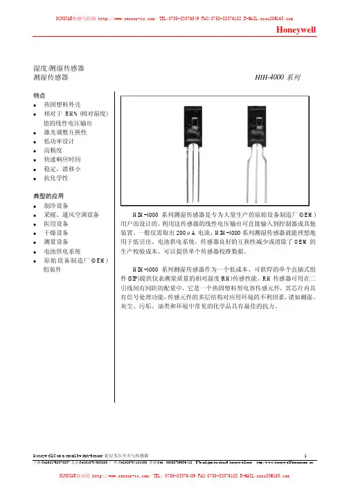
湿度/测湿传感器测湿传感器HIH-4000系列特点热固塑料外壳相对于RH%(相对湿度)值的线性电压输出激光调整互换性低功率设计高精度快速响应时间稳定,漂移小抗化学性典型的应用制冷设备采暖、通风空调设备医用设备干燥设备测量设备电池供电系统原始设备制造厂(OEM)组装件HIH-4000系列测湿传感器是专为大量生产的原始设备制造厂(OEM)用户而设计的。
利用这传感器的线性电压输出可直接输入到控制器或其他装置。
一般仅需取出200μA电流,HIH-4000系列测湿传感器就能理想地用于低引出、电池供电系统。
传感器良好的互换性减少或消除了OEM的生产校验成本。
可以提供单个传感器校准数据。
HIH-4000系列测湿传感器作为一个低成本、可软焊的单个直插式组件(SIP)提供仪表测量质量的相对湿度(RH)传感性能。
RH传感器可用在二引线间有间距的配量中,它是一个热固塑料型电容传感元件,其芯片内具有信号处理功能。
传感元件的多层结构对应用环境的不利因素,诸如潮湿、灰尘、污垢、油类和环境中常见的化学品具有最佳的抗力。
表1:性能规格在5.0 VDC供电电压和25°C时,除非另有规定%RH性能规格包括试验系统测量误差(±0.5%的典型值)参数最小值典型值最大值单位互换性(最佳配合直线)%RH0至60%RH-5 5%RH60%至100%-8 8互换性(二阶曲线)%RH±3.5%RH*精度(最佳配合直线)±3.5%RH**精度电压输出(二阶曲线)±2.5%RH 滞后性 3%RH重复精度±0.5整定时间70mSSec响应时间l/e指在缓慢流动的空气中15***稳定性(在1年内50%RH 的条件下)%RH±1.2****稳定性(50%RH条件下 ) %RH供电要求TBDVDC5.8供电电压 4μA供电电流500电压输出(一阶配合) V输出=V供电(0.0062(传感器RH)+0.16)电压输出(二阶曲线配合) V输出= 0.00003 (传感器RH)2 + 0.0281 (传感器RH) +0.820,在25°C时的典型数据温度补偿V输出=(0.0305+0.000044T-0.0000011T2) (传感器RH)+ (0.9237-0.0041T+0.000040T2)T=温度单位为°C工作温度-40 见图1 85 °C°F-40 185工作湿度 0见图1 100 %RH储存温度°C-40 125°F-40 257储存湿度见图2 %RH* 仅对HIH-400-003和-004型号而言。
特点:●3.8-30VDC 供电 ● 数字电流沉输出 ● 3针一列PCB 引脚● 方块霍尔设计消除了机械压力效应 ● 磁特性温度补偿● 可定制特殊的动作/释放点 ● 双极,单极,锁存型●很高的输出电流能力——最大绝对电流50mA ● 动点/释放点对称于零点高斯(双极锁存) ● 工作温度范围-40~150℃ ● 封装材料:Plaskon 3300H● 表面封装型号:SS400-S (切短或整形的引脚)SS400 内含整个温度范围的热平衡集成电路,负的温度补偿特性能与低成本磁钢负温度系数为最佳匹配带宽间隙调整提供了SS400 在3.8~30VDC 电源电压范围内特别稳定的工作特性。
SS400能连续输出20mA 电流,最大绝对电流为50mA.SS411A 双极3.8-3010mA 电流沉.40V 20mA 10µA.05µs 典型值1.5µs 最大值.15µs 典型值1.5µs 最大值G 70-701565-651560-601560-601265-651270-7010mT 7.0-7.01.56.5-6.51.56.0-6.01.56.0-6.01.26.5-6.51.27.0-7.01.0注:当锁存型突然掉电后,其输出在上电后可能改变状态,在足够强的磁场中,传感器的输出由所在磁场决定。
上升(10-90%)下降(90-10%)最大动作点最小释放点最小回差最大动作点最小释放点最小回差最大动作点最小释放点最小回差最大动作点最小释放点最小回差最大动作点最小释放点最小回差最大动作点最小释放点最小回差选型指南型号磁场类型供电电压(VDC )供电电流(最大值)输出类型输出电压(最大值)输出电流(最大值)*输出漏电流(最大值)输出开关时间Vcc=12V ,RL=1.6K C=20pF 磁特性-40℃0℃25℃85℃125℃150℃SS413A 双极3.8-3010mA 电流沉.40V 20mA 10µA.05µs 典型值1.5µs 最大值.15µs 典型值1.5µs 最大值SS441A 单极3.8-3010mA 电流沉.40V 20mA 10µA.05µs 典型值1.5µs 最大值.15µs 典型值1.5µs 最大值SS443A 单极3.8-3010mA 电流沉.40V 20mA 10µA.05µs 典型值1.5µs 最大值.15µs 典型值1.5µs 最大值SS449A 单极3.8-3010mA 电流沉.40V 20mA 10µA.05µs 典型值1.5µs 最大值.15µs 典型值1.5µs 最大值SS461A 锁存3.8-3010mA 电流沉.40V 20mA 10µA.05µs 典型值1.5µs 最大值.15µs 典型值1.5µs 最大值SS466A 锁存3.8-3010mA 电流沉.40V 20mA 10µA.05µs 典型值1.5µs 最大值.15µs 典型值1.5µs 最大值G 140-14020140-14020140-14020140-14020140-14020140-14020mT 14.0-14.02.014.014.02.014.0-14.02.014.0-14.02.014.0-14.02.014.0-14.02.0G 1352015117201811520201201515123158125105mT 13.52.01.511.72.01.811.52.02.012.01.51.512.31.50.812.51.00.5G 21580251908025180752518070151906010200555mT 21.58.02.519.58.02.518.07.52.5187.01.519.06.01.020.05.50.5G 435210304002303039023530400215304102003042018530mT 43.521.03.040.023.03.039.023.53.040.021.53.041.020.03.042.018.53.0G 110-1105090-905085-855085-8550100-10050110-11050mT 11.0-11.05.09.0-9.05.08.5-8.55.08.5-8.55.010.0-10.05.011.0-11.05.0G 200-200200185-185200180-180200180-180190180-180160185-185140mT 20.0-20.020.018.5-18.520.018.018.020.018.0-18.019.018.0-18.016.018.5-18.514.0注:可订购安装在线带和卷带上的SS400,引脚上间距0.1”, 每个卷带3000个SS400传感器。
目录:水系统传感器 (2)水流开关WFS-1001-H (2)液位开关MAC-3-5M (2)水管式压差传感器P7620C (3)水管式压力传感器P7620A (4)流量变送器8550+2517 (5)VF20T浸入式温度传感器 (5)风系统传感器 (7)DPS系列气流压差开关 (7)DPTM系列压差变送器 (7)风管式温度传感器LF20 (8)风管式温度传感器LF20-C (9)室外温度传感器T7416A1022 (9)室内温度传感器T7412A1000 (9)室内温度传感器CTR21 (10)风管式温湿度传感器H7050B1018 (10)风管式温湿度变送器H7050B1117 (11)室内温湿度变送器H7030A1000 (12)室内温湿度传感变送器H7012B1023 (12)室内温湿度传感器CTR21-H (13)风管式温湿度传感器H7015B1020 (14)室外温湿度传感变送器H7508A1042 (14)CDS2000 系列二氧化碳传感器 (15)C7110C1001(替换已停产的AQS51) 系列二氧化碳传感器 (15)AQS71-KAM(替换已停产的AQS51-KAM) 系列二氧化碳传感器 (16)GD250W3E 系列一氧化碳传感器 (17)C7110A1005系列房间空气质量传感器 (17)L4064K1006B 高温断路开关,手动复位 (18)T6950A1000 低温短路开关,手动复位 (18)数字化挂墙模块T7560 温度传感器 (19)数字化挂墙模块T7460 温度传感器 (19)水系统传感器水流开关 WFS-1001-H应用∙ WFS 水流开关具有SPDT 输出,性能优异,高精度可靠性,可安装在水管和对铜无腐蚀性液体中,当液体流量达到整定速率时,可不到整定点,其一个回路关闭,另一个回路打开,典型应用于连锁作用或断流保护的场所。
∙ WFS 系列开关仅用0℃以上液体介质,它亦可于高盐或氯气的液体,但是非易燃介质。

High TemperatureIndustrial VRS Magnetic Speed SensorsDESCRIPTIONHigh Temperature VRS sensors are designed for use inapplications where the sensor is exposed to temperatures up to 260 ºC [450 ºF]. Sealed Front-End versions are available for applications where the sensor is exposed to fluids, lubricants or adverse environmental conditions.Passive VRS (Variable Reluctance Speed) Magnetic Speed sensors are simple, rugged devices that do not require an external voltage source for operation.A permanent magnet in the sensor establishes a fixedmagnetic field. The approach and passing of a ferrous metal target near the sensor’s pole piece (sensing area) changes the flux of the magnetic field, dynamically changing its strength. This change in magnetic field strength induces a current into a coil winding which is attached to the output terminals.The output signal of a VRS sensor is an ac voltage that varies in amplitude and wave frequency as the speed of themonitored device changes, and is usually expressed in peak to peak voltage (Vp-p).One complete waveform (cycle) occurs as each target passes the sensor’s pole piece. If a standard gear were used as a target, this output signal would resemble a sine wave if viewed on an oscilloscope.Honeywell also offers VRS sensors for general purpose, high output, power output, high resolution and hazardous location applications, as well as low-cost molded OEM versions.FEATURES• Self-powered operation• Direct conversion of actuator speed to output frequency • Simple installation • No moving parts• Designed for use over a wide range of speeds • Adaptable to a wide variety of configurations• Customized VRS products for unique speed sensingapplications• Housing diameters: 5/8 in (M16), 3/8 in (M12),1/4 in (8M)• Housing material/style: stainless steel threaded • Terminations: MS3106 connector, preleaded • Output voltages: 4.7 Vp-p to 125 Vp-pPOTENTIAL APPLICATIONS• Engine RPM (revolutions per minute) measurement onaircraft, automobiles, boats, buses, trucks and rail vehicles• Motor RPM measurement on drills, grinders, lathes andautomatic screw machines• Motor RPM measurement on precision camera, taperecording and motion picture equipment• Process speed measurement on food, textile, paper,woodworking, printing, tobacco and pharmaceutical industry machinery• Motor speed measurement of electrical generatingequipment• Speed measurement of pumps, blowers, mixers, exhaustand ventilating fans• Flow measurement on turbine meters• Wheel-slip measurement on autos and locomotives • Gear speed measurementHigh Temperature2 /sensing5/8 INCH (M16*) SENSORS (All dimensions for reference only. mm/[in]) *Contact Honeywell for availability of metric mounting thread versions.LOW RESISTANCE COILS FOR HIGH FREQUENCY APPLICATIONS General SpecificationsTest Condition SpecificationsParameter Characteristic Parameter Characteristic Parameter Characteristic Min. output voltage 25 Vp-p Inductance 30 mH max. Surface speed 25 m/s[1000 in/s]Coil resistance 65 Ohm typ. Gear pitch range 24 DP (module 1.06) or coarser Gear 20 DP(module 1.27)Pole piece diameter 2,69 mm [0.106 in] Optimum actuator 20 DP (module 1.27) Air gap 0,127 mm[0.005 in]Min. surface speed0,50 m/s [20 in/s] typ. Max. operating frequency50 kHz typ. Operating temp. range-55 ºC to 230 ºC [-67 ºF to 450 ºF] Vibration N/A Mounting thread 5/8-18 UNF-2ATerminationMS3106 connectorLoadresistance100 kOhmHIGH RESISTANCE COILS FOR MAXIMUM OUTPUT VOLTAGE APPLICATIONS General SpecificationsTest Condition SpecificationsParameter Characteristic Parameter Characteristic Parameter Characteristic Min. output voltage 125 Vp-p Inductance 450 mH max. Surface speed 25 m/s[1000 in/s]Coil resistance 1055 Ohm typ. Gear pitch range 24 DP (module 1.06) or coarser Gear 20 DP(module 1.27)Pole piece diameter 2,69 mm [0.106 in] Optimum actuator 20 DP (module 1.27) Air gap 0,127 mm [0.005 in] Min. surface speed 0,25 m/s [10 in/s] typ. Max. operating frequency 15 kHz typ. Operating temp. range-55 ºC to 230 ºC [-67 ºF to 450 ºF] Vibration N/A Mounting thread 5/8-18 UNF-2ATerminationMS3106 connectorLoad resistance100 kOhmIndustrial VRS Magnetic Speed SensorsHoneywell Sensing and Control 35/8 INCH (M16*) SENSORS CONTINUED (All dimensions for reference only. mm/[in]) *Contact Honeywell for availability of metric mounting thread versions.NOMINAL RESISTANCE COILS FOR LOW IMPEDANCE LOAD APPLICATIONS General SpecificationsTest Condition SpecificationsParameter Characteristic Parameter Characteristic Parameter Characteristic Min. output voltage 45 Vp-p Inductance 85 mH max. Surface speed 25 m/s[1000 in/s]Coil resistance 141 Ohm typ. Gear pitch range 12 DP (module 2.11) or coarser Gear 8 DP(module 3.17)Pole piece diameter 4,75 mm [0.187 in] Optimum actuator 8 DP (module 3.17) Air gap 0,127 mm [0.005 in]Min. surface speed 0,38 m/s [15 in/s] typ. Max. operating frequency 40 kHz typ. Operating temp.range-55 ºC to 230 ºC [-67 ºF to 450 ºF] Vibration N/A Mounting Thread 5/8-18 UNF-2ATerminationMS3106 ConnectorLoadresistance1.25 kOhmHigh Temperature4 /sensing5/8 INCH SEALED FRONT-END SENSORS (All dimensions for reference only. mm/[in]) (No metric available.)NOMINAL RESISTANCE COILS FOR LOW IMPEDANCE LOADS APPLICATIONS General SpecificationsTest Condition SpecificationsParameter Characteristic Parameter Characteristic Parameter Characteristic Min. output voltage60 Vp-p Inductance 85 mH max. Surface speed 25 m/s[1000 in/s]Coil resistance 120 Ohm to 162 Ohm Gear pitch range 12 DP (module 2.11) or coarser Gear 8 DP(module 3.17)Pole piece diameter 4,39 mm [0.173 in] Optimum actuator 8 DP (module 3.17) Air gap 0,127 mm[0.005 in]Min. surface speed0,38 m/s [15 in/s] typ. Max. operating frequency40 kHz typ. Operating temp. range-54 ºC to 220 ºC [-65 ºF to 428 ºF] Vibration N/AMounting Thread 5/8-18 UNF-2ATerminationMS3106 connectorLoadresistance 1.25 kOhmIndustrial VRS Magnetic Speed SensorsHoneywell Sensing and Control 53/8 INCH (M12*) SENSORS (All dimensions for reference only. mm/[in]) *Contact Honeywell for availability of metric mounting thread versions.General SpecificationsTest Condition SpecificationsParameter Characteristic Parameter Characteristic Parameter Characteristic Min. output voltage15 Vp-p Inductance 31 mH max. Surface speed 25 m/s[1000 in/s]Coil resistance 110 Ohm max. Gear pitch range 26 DP (module 0.98) or coarser Gear 20 DP(module 1.27)Pole piece diameter 2,36 mm [0.093 in] Optimum actuator 24 DP (module 1.06) ferrous metal gear Air gap 0,127 mm[0.005 in]Min. surface speed0,75 m/s [20 in/s] typ. Max. operating frequency50 kHz typ. Operating temp. range-40 ºC to 205 ºC [-40 ºF to 400 ºF] Vibration N/A Mounting thread 3/8-24 UNF-2ATermination24 AWG Teflon-insulated leadsLoadresistance 100 kOhmHigh Temperature6 /sensing1/4 INCH (M8*) MINIATURE SENSORS (All dimensions for reference only. mm/[in]) *Contact Honeywell for availability of metric mounting thread versions.General SpecificationsTest Condition Specifications Parameter Characteristic Parameter Characteristic Parameter CharacteristicMin. output voltage 4.7 Vp-p Inductance 13 mH max.Surface speed 25 m/s[1000 in/s]Coil resistance 137 Ohm max. Gear pitch range36 DP (module 0.70) or coarserGear 20 DP(module 1.27) Pole piece diameter 1 mm [0.040 in] Optimum actuator 28 DP (Module 0.90)ferrous metal gear Air gap 0,127 mm [0.005 in] Min. surface speed0,89 m/s [35 in/s] typ. Max. operating frequency70 kHz typ.Operating temp. range-40 ºC to 230 ºC [-40 ºF to 450 ºF] Vibration Mil-Std 202F Method 204DMounting thread 1/4-40 UNS-2ATermination30 AWG Teflon-Insulated LeadsLoadresistance100 kOhmIndustrial VRS Magnetic Speed SensorsHoneywell Sensing and Control 71/4 INCH SEALED FRONT-END SENSORS (All dimensions for reference only. mm/[in]) (No metric available.)General SpecificationsTest Condition SpecificationsParameter Characteristic Parameter Characteristic Parameter Characteristic Min. output voltage 5.2 Vp-p Inductance 85 mH max. Surface speed 25 m/s[1000 in/s]Coil resistance 20 Ohm to 45 Ohm Gear pitch range 36 DP (module 0.70) or coarser Gear 20 DP(module 1.27)Pole piece diameter 1 mm [0.040 in] Optimum actuator 28 DP (module 0.90) ferrous metal gear Air gap 0,127 mm [0.005 in]Min. surface speed 0,89 m/s [35 in/s] typ. Max. operating frequency 70 kHz typ. Operating temp.range-73 ºC to 230 ºC [-100 ºF to 450 ºF] Vibration Mil-Std 202F Method 204DMounting Thread 1/4-40 UNS-2ATermination 28 AWG Teflon-insulated leadsLoadresistance 100 kOhmAutomation and Control Solutions Sensing and Control Honeywell1985 Douglas Drive North Minneapolis, MN 55422 /sensing 005877-1-EN IL50 GLO Printed in USAMarch 2007Copyright © 2007 Honeywell International Inc. All rights reserved.WARNINGPERSONAL INJURYDO NOT USE these products as safety or emergency stop devices or in any other application where failure of the product could result in personal injury.Failure to comply with these instructions could result in death or serious injury.WARRANTY/REMEDYHoneywell warrants goods of its manufacture as being free of defective materials and faulty workmanship. Honeywell’s standard product warranty applies unless agreed to otherwise by Honeywell in writing; please refer to your orderacknowledgement or consult your local sales office for specific warranty details. If warranted goods are returned to Honeywell during the period of coverage, Honeywell will repair or replace, at its option, without charge those items it finds defective. The foregoing is buyer’s sole remedy and is in lieu of all other warranties, expressed or implied, including those of merchantability and fitness for a particular purpose. In noevent shall Honeywell be liable for consequential, special, or indirect damages.While we provide application assistance personally, through our literature and the Honeywell web site, it is up to the customer to determine the suitability of the product in the application.Specifications may change without notice. The information we supply is believed to be accurate and reliable as of this printing. However, we assume no responsibility for its use.WARNINGMISUSE OF DOCUMENTATION• The information presented in this product sheet is forreference only. Do not use this document as a product installation guide.• Complete installation, operation, and maintenanceinformation is provided in the instructions supplied with each product.Failure to comply with these instructions could result in death or serious injury.SALES AND SERVICEHoneywell serves its customers through a worldwide network of sales offices, representatives and distributors. For application assistance, current specifications, pricing or name of the nearest Authorized Distributor, contact your local sales office or:E-mail:*********************Internet: /sensing Phone and Fax:Asia Pacific +65 6355-2828 +65 6445-3033 Fax Europe +44 (0) 1698 481481+44 (0) 1698 481676 FaxLatin America +1-305-805-8188+1-305-883-8257 Fax USA/Canada +1-800-537-6945+1-815-235-6847 +1-815-235-6545 Fax。

I Connected IndustriaISMARTLINE PRESSURE SELECTION GUIDELINESRedefining Smart.SmartLine Pressure TransmittersHoneywell’s SmartLine® pressure measurement system sets the standard with its industry-leading total performance, even in harsh process environments. With the best control system integration and unique features such as modularity, a graphics display and universal terminals, SmartLine offers the lowest total cost of ownership.Leading PerformanceSmartLine provides better performance with industry leading accuracy, response time and stability. When combined with Honeywell’s proven static pressure and temperature compensation, the unbeatable total performance is better than 0.12% of span under actual process conditions.Lowest Total Cost of Ownership• H oneywell’s unique approach to modularity helps reduce maintenance costs and make repairs safer and faster. With the ability to repair the transmitter in place, the need to break a process line connection is avoided, even in an intrinsically safe environment. And with no need to stock complete units, inventory costs are lower.• A n advanced graphics display and three button external configuration option provide capabilities for field operators to more efficiently perform tasks,solve problems and avoid errors with no need for a handheld device. The display shows rich graphics, bar graphs, trends and messages from the control room.• W ith SmartLine’s universal terminals, wiring can be reversed without damaging or affecting the normal operation of the transmitter. This avoids costly rework on large installations where multiple contractors may use different wiring standards and eliminates return trips to re-wire “incorrectly wired” devices.SmartLine Connection Advantage• T ransmitter Messaging allows the operator to send and display custom messages to the display so field operators can quickly identify the right transmitter and task.•M aintenance Mode Indication displays a message on the display that the transmitter and/or the loop is in a mode suitable for maintenance. • U nique Tamper Reporting notifies the control room that an attempt to change a write-protected configuration has been made or that the write protection has been switched off.•F ield Device Manager (FDM) is Honeywell’s centralized asset management system for smart field device configuration and maintenance. When SmartLine data is integrated into FDM, users can create hierarchical screen displays for quick and easy views of device health from areas of the plant or process.• W ith comprehensive testing, Honeywell provides trouble-free integration for faster startups and reliability. The tests even include other suppliers’ configuration tools.ST800ST700SMV800 Performance CharacteristicsAccuracy • U p to 0.0375% span standard• 0.025% span optional highaccuracy • B asic: up to 0.065% of span• S tandard: up to 0.05% of span•P V1 DP – up to 0.04% of span• P V2 SP – up to 0.0375% of span• P V3 PT – 0.2 °C RTD – Pt 100• P V4 – mass flow accuracyup to 0.6%Stability• U p to 0.01% per year for ten years• B asic: up to 0.025% per year for5 years• S tandard: up to 0.02% per yearfor 5 years• U p to 0.0625% of URL per yearResponse Time• A s fast as 80 ms• A s fast as 100 ms•A s fast as 144 ms for DP (PV1) Total Performance• U p to 0.12%• U p to 0.2%• M ass flow performance is up to 0.6% Turndown Ratios up to 400:1• T urndown ratios up to 400:1• T urndown ratios up to 100:1• T urndown ratios up to 400:1 Compound Characterized Ranges• Y es• Y es• Y esTemperature & Static PressureCompensated• Y es• Y es• Y esProduct Features & OptionsMeasured Parameters• D ifferential pressure staticpressure • D ifferential pressure staticpressure• D ifferential pressure, staticpressure, process temperatureCaluclated Parameters• V olume flow• V olume flow• V olume flow, mass flow Support for Flow Algorithms• N A• N A• A SME MFC-3M, ISO5167, Gost8.586, AGA3, ASME MFC 14MSupport for Flow Elements• N A• N A• O rifice, Venturi, Flow Nozzle,Pitotube, IFO, Standard V cone,Wafer cone, WedgeHART® 7, DE & F OUNDATION™Fieldbus Communication Protocols• Y es• Y es• D E, HART 7Universal Terminals• Y es• S tandard: Yes• Y esModular Design Components• S imple faster repairs with lessdowntime • S imple faster repairs withless downtime• S imple faster repairs withless downtimeSmartLine Connection Advantage with Experion®• T ransmitter Messaging*• M aintenance Mode Indication• T amper Alerts*• F DM Plant Area Views• C omprehensive Experionintegration testing• T amper Alerts* (Standard only)• F DM Plant Area Views• T ransmitter Messaging*• M aintenance Mode Indication• T amper Alerts*• F DM Plant Area Views• C omprehensive Experionintegration testingSIL 2 Certified/SIL 3Capable Standard• Y es• Y es• N o Certified for Dual Seal Compliance• Y es• Y es• Y esComprehensive & AdvancedDiagnostics• Y es• Y es• Y esUser Interface Options• O ptional basic alphanumeric display• O ptional advanced graphics display• M ultiple PV display screens includingbar graph and trend displays• C omprehensive diagnostic messages• S upports transmitter messagingand maintenance mode indication• C omprehensive EDDs & DTMsfor remote configuration• O ptional external 3-buttonprogramming capability • S T700 Basic: supports Standarddisplay with internal and/orexternal 2-button configurationST700 Standard: supportsStandard display with internal2-button configuration / Basicdisplay with external three buttonconfiguration• Diagnostic notifications•C omprehensive EDDs & DTMsfor remote configuration• O ptional external two (Basic)or three (Standard) buttonprograming capability• N A•O ptional advanced graphics display• M ultiple PV display screens includingbar graph and trend displays• C omprehensive diagnostic messages• S upports transmitter messagingand maintenance mode indication• C omprehensive EDDs & DTMs forremote configuration• O ptional external 3-buttonlimited programming capOptional Extended Warranties• 1, 2, 3, 4 and 15 year warranties• 1, 2, 3 and 4 year warranties• 1, 2, 3, 4 and 15 year warranties *Also compatible with other HART 7 enabled hostsStandard, basic or advanced digital display as determined by the application requirementsUniversal or traditional wiring terminal boards with standard or lightning-protected optionsIt takes only a matter of minutes to replace the electronics, even in the field under power with no re-calibration required. This avoids the time-consuming procedure of removing a sensor from a pipeline or network, particularly in highly critical processes.Best of all, Honeywell’s unique modularity reduces inventory requirements and lowers overall operating costs.LOWER YOUR TOTAL COST OF OWNERSHIPWith Plug-In Modules, Users Can Easily Add or UpgradeAll SmartLine Pressure Transmitters are modular in design, making it easy to replace hardware, add indicators, change electronic modules or even meter bodies without affecting overall performance or impinging on approval body certifications.Flexible ConfigurationIn addition to configuring with any hand-helddevice or through asset management DTMs, users can configure the transmitters through externally accessible buttons, even in an intrinsically safe, Class I, Div. 1 environment.Now, whether on the bench or in the field, configure, change tag information, change languages and even more without needing a handheld device.SMARTLINE PRESSURE SELECTION GUIDEModel Types, Ranges and SpansModelUpper Range Lower Range Max. SpanUnitsStandard Accuracy % of Span Turndown CapabilityTwo- or three-button external configurationField-exchangeable communication modules to deploy HART , Honeywell Digital Enhanced (DE) or FOUNDATION Fieldbus communicationAdvanced Graphics LCD Display• U p to eight separate screens with three formats to meet unique display requirements: process variable, bar graph and trend• F ull library of engineering units with the ability to add custom units• Configurable screen rotation timing • Supports multiple languages • Two diagnostic indications• 90-degree position adjustments to facilitate all installation positions.For more informationTo learn more about Honeywell’s SmartLine Pressure Transmitters, visit /smartlineor contact your Honeywell account manager. Honeywell Process Solutions512 Virginia DriveFort Washington, PA 19034 USAHoneywell House, Arlington Business Park Bracknell, Berkshire, England RG12 1EB17 Changi Business Park Central 1 Singapore 486073 SmartLine® and Experion® are registered trademarks of Honeywell International Inc. HART® is a registered trademark andF OUNDATION™ Fieldbus is a trademark of the FieldComm Group.PO-16-01-ENG | 11/16©2016 Honeywell International Inc.。

Honeywell/Commercial Switch&Sensor 霍尼韦尔商业开关与传感器上海:Tel:021-******** 北京:Tel:010-******** 深圳:Tel:0755-******** 广州:Tel:020-******** e-mail:jian.bo.zhou@ /sensing模拟霍尔位置传感器*-40°C-125°C**包括负载,典型在25°C /最大在-40°C 下***@Vs=5VDC 只限于SS94A1B @Vs=8VDC 适用其它型号+曲线始末端点直线法++陶瓷背面镀银与引脚电气连接规定用2.2K Ω电阻,除非另外标注零点电压(0高斯时电压)和灵敏度与供电电压线性比率变化特点:●单个电流沉或电流源输出 ● 提高的温度稳定性 ● 三针一列PCB 引脚● 激光修正的薄膜和厚膜电阻,减少了灵敏度变化,并带温度补偿 ● 敏感磁场强度±100到±2500高斯性能:SS9系列利用新的霍尔集成电路芯片。
提高了温度稳定度和性能。
经激光修正的陶瓷基底上的厚膜电阻及集成电路上的薄膜电阻,减少了传感器的零点和灵敏度的温飘,使得每一个器件有相同的灵敏度。
安装尺寸(仅供参考)SS94A 选型指南规格主要特点供电电压(VDC )*供电电流(mA 最大值)**输出电流(mA )电源沉或源反应时间(µsec.)磁特性***满量程*测量磁场范围(guass )*灵敏度(mV/guass@25℃)线性度(%量程)输出Vout(0高斯@25℃)***温度误差(所有%S 以25℃值为基准)*零点(%/℃)灵敏度(%/℃)SS94A1通用6.6—12.613(典型值)30(最大值)1(最大值)3(典型值).625Vs -500-+5005.0±.1-0.8(典型值)-1.5(最大值)4.00±0.04V± .02± .02SS94A1B 5VDC 工作4.5—8.08(典型值)17.5(最大值)1(最大值)3(典型值).375Vs -500-+5001.875±1.00-0.8(典型值)-1.5(最大值)2.50±0.05V± .025± .025SS94A1E 低漂移6.6—12.613(典型值)30(最大值)1(最大值)3(典型值).625Vs -500-+5005.0±.1-0.8(典型值)-1.5(最大值)4.00±0.04V± .01± .02SS94A1F 高灵敏度6.6—12.613(典型值)30(最大值)1(最大值)3(典型值).625Vs -100-+100 25.0±.5-0.8(典型值)-1.5(最大值)4.00±0.08V± 1.0± .02-.055SS94A2噪声屏蔽++6.6—12.613(典型值)30(最大值)1(最大值)3(典型值).625Vs -500-+5005.0±0.1-0.8(典型值)-1.5(最大值)4.00±0.04V± .02± .02SS94A2C 噪声屏蔽++6.6—12.613(典型值)30(最大值)1(最大值)3(典型值).625Vs -1000-+10002.50±0.05-0.8(典型值)-1.5(最大值)4.00±0.04V± .0125± .02SS94A2D 噪声屏蔽++6.6—12.613(典型值)30(最大值)1(最大值)3(典型值).625Vs -2500-+25001.00±0.02-0.8(典型值)-1.5(最大值)4.00±0.04V± .007± .02应用考虑:输出电压被嵌在高端电压,嵌位电位可低至9V ,输出不会超过此嵌位电压而不管磁场强度和供电电压大小。
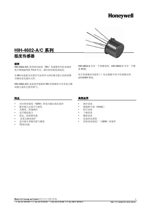
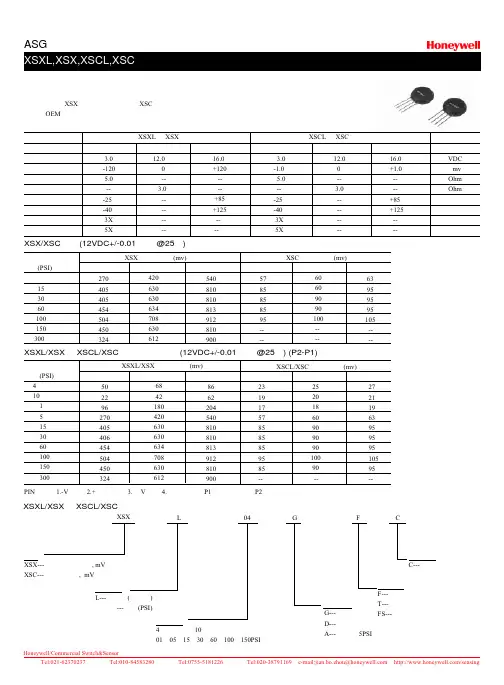
先进的硅结构的压力传感器,集中了硅结构传感技术,温度补偿,校正,于—体,且低成本的封装。
XSX系列不带温度补偿, XSC系列带温度补偿,它们的设计,成本低,尺寸小,适合于OEM应用。
供电电压零点输入阻抗输出阻抗工作温度储存温度安全压力破坏压力最小值3.0-1205.0---25-403X5X典型值12.0--3.0--------最大值16.0+120----+85+125----最小值3.0-1.05.0---25-403X5X典型值12.0--3.0--------最大值16.0+1.0----+85+125----单位VDCmvOhmOhm℃℃量程量程XSXL和XSX XSCL和XSCXSX/XSC绝压(12VDC+/-0.01供电@25℃)满量程压力(PSI)5 15 30 60 100 150 300最小值270405405454504450324XSX满量程输出(mv)典型值420630630634708630612最大值540810810813912810900最小值5785858595----XSC满量程输出(mv)典型值60609090100----最大值63959595105----XSXL/XSX和XSCL/XSC表压和差压输出(12VDC+/-0.01供电@25℃) (P2-P1)满量程压力(PSI)4英寸水柱10英寸水柱 15153060100150300最小值502296270405406454504450324XSXL/XSX满量程输出(mv)典型值6842180420630630634708630612最大值8662204540810810813912810900最小值231917578585859585--XSCL/XSC满量程输出(mv)典型值2520186090909010090--最大值2721196395959510595--PIN定义:1.-V供电 2.+输出信号 3.+V供电4.-输出信号 P1口:干燥空气 P2口:与尼龙外壳,硅兼容的介质XSXL/XSX和XSCL/XSC系列选型指南系列XSX---不补偿,不校正, mVXSC---补偿且校正, mV压力测量L---低压力(英寸水)无字母---压力(PSI)压力范围4英寸水柱,10英寸水柱01,05,15,30,60,100,150PSI 压力类型G---表压D---差压A---绝压≥5PSI精度选项C---经济型导气选项F---轴向T---径向FS---轴向偏置XSX L G F C04硅结构压力传感器未温度补偿已温度补偿:安装尺寸 (mm/in):XSXL/XSX AND XSCL/XSC SeriesEQUIVAlENT CIRCUITPlN DESOGNATIONS1.- V 电源电压2.+输出信号3. + V 电源电压4.- 输出信号XSCL/XSC Differential PortXSXL, XSXXSCL, XSC SeriesXSC Ceramic without PortXSC Ceramic with Port(F)。
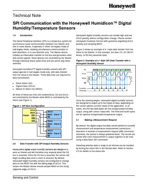
Technical NoteSPI Communication with the Honeywell HumidIcon™ Digital Humidity/Temperature SensorsSensing and Control1.0 IntroductionThe Serial Peripheral Interface (SPI) is a simple bus system for synchronous serial communication between one Master and one or more Slaves. It operates in either full-duplex mode or half-duplex mode, allowing simultaneous communication in both directions, or in one direction only. The Master device initiates an information transfer on the bus and generates clock and control signals. Slave devices are controlled by the Master through individual Slave select lines and are active only when selected.Honeywell HumidIcon ™ digital humidity sensors with SPI output operate in half-duplex mode only, with data transfer from the Slave to the Master. Three data lines are required for data transmission:Slave Select (SS)Signal Clock (SCLK)Master-In-Slave Out (MISO)All three of these bus lines are unidirectional. SS and SCLK are controlled by the Master while MISO is controlled by the Slave (see Figure 1).2.0 Data Transfer with SPI Output Humidity SensorsHoneywell’s digital output humidity sensors are design ed to work as Slaves and will therefore only respond when the SS line is asserted. Once the SS line is asserted, the sensor will begin sending data once a clock is received. By default, Honeywell digital humidity sensors are configured to change data on the MISO line with the falling edge of SCLK. This means the Master device should sample MISO on the rising (opposite edge) of SCLK.Honeywell digital humidity sensors can handle high and low SCLK polarity without configuration change. Please contact Honeywell Customer Service with questions regarding SCLK polarity and sampling MISO.Figure 2 shows an example of a 1 byte data transfer from the Slave to the Master. In this example, the data 101 (01100101 binary, or 65 hex) would be read.Figure 2. Example of a 1 Byte SPI Data Transfer with aOnce the clocking begins, Honeywell digital humidity sensors are designed to output up to four bytes of data, depending on the sensor options and the needs of the application. In all cases, the first two data bytes are the compensated humidity output, along with sensor status bits. The third and fourth bytes are for optional compensated temperature output. 2.1 Making a Measurement RequestBy default, the digital output humidity sensor performs humidity measurement and temperature measurement conversions whenever it receives a measurement request (MR) command; otherwise, the sensor is always powered down. The results are stored after each measurement in output registers to be read using a data fetch (DF) command.Detecting whether data is ready to be fetched can be handled by testing the status bits in the fetched data. Refer to Section 2.5 for details of the status bits.SPI Communication with the Honeywell HumidIcon™ Digital Humidity/Temperature Sensors2 Honeywell Sensing and Control2.2 Humidity and Temperature Measurement Request To wake up the humidity sensor and complete a measurement cycle, an MR command is used. The complete measurement cycle performs a humidity measurement and a temperature measurement and stores the results. As shown in Figure 3, an MR command is a read of eight or more bits, ignoring the data that is returned.A DF (Data Fetch) command must be completed before sending another measurement request command to start a new measurement cycle.2.3 Humidity Data FetchTo receive a compensated humidity reading, the Master generates the necessary clock signal after activating thesensor with the Slave select line. The sensor will transmit up to four bytes of data: the first two bytes contain the compensated humidity output, and the second two bytes contain the compensated temperature output.If only the compensated humidity value is required, the Master can terminate communication by stopping the clock and deactivating the slave select line after the second byte. An example of the communication is shown in Figure 4.2.4 Humidity and Temperature Data FetchThe optional corrected temperature data is read out with 14 bitresolution. By reading out the third and fourth bytes of data from the sensor, the complete 14 bit optional compensated temperature value can be read, as shown in Figure 5.When reading the full 14 bit resolution temperature output, the two least significant bits of the fourth data byte are “Do Not Care” and should be ignored.Figure 5. SPI Humidity and Temperature Data FetchPacket = [ {S(1:0),C(13:8)}, {C(7:0)}, {T(13:6)},{T(5:0),xx} ]Where:S(1:0) = Status bits of packetC(13:8) = Upper six bits of 14-bit humidity data C(7:0) = Lower eight bits of 14-bit humidity data T(13:6) = Corrected temperature dataT(5:0),xx = Remaining bits of corrected temperature data forfull 14-bit resolutionHiZ = High impedance 2.5 Status BitsHoneywell digital output humidity sensors offer status bits to ensure robust system operation in critical applications. The sensor status is indicated by the first two most significant bits of data byte 1 (See Table 1).Note 1: Command Mode is used for programming the sensor. This mode should not be seen during normal operationWhen the status bits read “01”, “s tale” data is indicated. This means that the data in the output buffer of the sensor has already been fetched by the Master, and has not yet beenupdated with the new data from the current measurement cycle. This can happen when the Master polls the data quicker than the sensor can update the output buffer.SPI Communication with the Honeywell HumidIcon™ Digital Humidity/Temperature SensorsHoneywell Sensing and Control 33.0 Measurement CycleFigure 6 shows the measurement cycle for the humidity sensor. The measurement cycle time is typically 36.65 ms fortemperature and humidity readings. It is recommended that the user wait until the measurement cycle has completed rather than polling for data to reduce current consumption and noise.Figure 6. Measurement Cycle for Humidity and4.0 Calculation of the Humidity Value from the Digital OutputFor Honeywell humidity sensors, the output of the device is simply a 14 bit number representing between 0 %RH and 100 %RH (see Equation 1):0 %RH = 0 counts100 %RH = 214- 2 counts5.0 Calculation of Optional Temperature from the Digital OutputFor Honeywell Humidity Sensors with the optionalcompensated temperature output, the output of the device is simply a 14 bit number representing between -40 ºC and 125 ºC (see Equation 2):-40 ºC = 0 counts125 ºC = 214– 2 counts6.0 Timing and Level Parameters (See Figure7.)SPI Communication with the Honeywell HumidIcon™ Digital Humidity/Temperature SensorsSensing and ControlHoneywell1985 Douglas Drive NorthGolden Valley, MN 55422 /sensing 009071-1-ENJuly 2012Copyright © 2012 Honeywell International Inc. All rights reserved.WARRANTY/REMEDYHoneywell warrants goods of its manufacture as being free of defective materials and faulty workmanship. Honeywell’s standard product warranty applies unless agreed to otherwise by Honeywell in writing; please refer to your order acknowledgement or consult your local sales office for specific warranty details. If warranted goods are returned to Honeywell during the period of coverage, Honeywell will repair or replace, at its option, without charge those items it finds defective. The foregoin g is buyer’s sole remedy and is in lieu of all other warranties, expressed or implied, including those of merchantability and fitness for a particular purpose. In no event shall Honeywell be liable for consequential, special, or indirect damages.While we provide application assistance personally, through our literature and the Honeywell web site, it is up to the customer to determine the suitability of the product in the application.Specifications may change without notice. The information we supply is believed to be accurate and reliable as of this printing. However, we assume no responsibility for its use. SALES AND SERVICEHoneywell serves its customers through a worldwide network of sales offices, representatives and distributors. For application assistance, current specifications, pricing or name of the nearest Authorized Distributor, contact your local sales office or:E-mail:*********************Internet: /sensingPhone and Fax:Asia Pacific +65 6355-2828+65 6445-3033 FaxEurope +44 (0) 1698 481481+44 (0) 1698 481676 FaxLatin America +1-305-805-8188+1-305-883-8257 FaxUSA/Canada +1-800-537-6945+1-815-235-6847+1-815-235-6545 Fax。
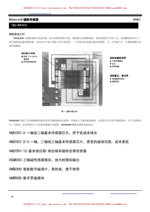
磁阻敏感元件Honeywell在磁阻敏感元件(图3),由长而薄的玻莫合金(一种铁镍合金)薄膜制成。
利用标准的半导体工艺,将薄膜附着硅片上。
四个磁阻组成惠斯通电桥。
同时在硅平面上制作了两个电流带,一个用来置位或复位输出的极性、另一个用来产生一个偏置磁场以补偿环境磁场。
Honeywell提供了在场地磁场范围内非常灵敏的磁阻传感器。
可测量几十微高斯的磁场,这是霍尔元件所不能做到的。
由于它的体积小,全固态,在某些场合下可以取代磁通门传感器。
Honeywell磁阻传感器家族包括:HMC1001/2-一轴或二轴基本传感器芯片,用于低成本场合HMC1021/2/3-一轴,二轴或三轴基本传感器芯片,更宽的磁场范围,成本更低HMC1501/12-基本线位移/角位移和旋转位移传感器HCM2003-三轴磁传感器模块,放大的模拟输出HMR2300-智能数字磁场计,高性能,便于使用HMR3000-数字罗盘模块特性·带微处理器的智能传感器·低成本,使用方便-一插即用·量程:±2Gauss,分辨率67μGauss·采样速度可选:10~157采样点/秒·三轴数字量输出:BCD码,ASCⅡ码或二进制码·9600或19.6K波特率可选择·符合RS-485标准,总线上连接多个单元·符合RS-232标准进行单点读数应用·航空用和船用罗盘·车辆遥感检测(侧滚/俯仰/偏航) ·过程控制·实验室仪器·异常检测·交通车辆检测·保安系统概述霍尼韦尔公司生产的三轴智能数字磁场计(HMR)可检测磁场的强度和方向,并与计算机直接通讯,输出X、Y、Z三个轴的分量。
用三个独立的桥路定向检测磁场的X、Y、Z轴的分量,电桥输出端相应电压的变化通过一个16位AD转换器转换为数字量。
可输入命令组态数据采样速率、输出格式、平均读数和零点偏移(见表1)。
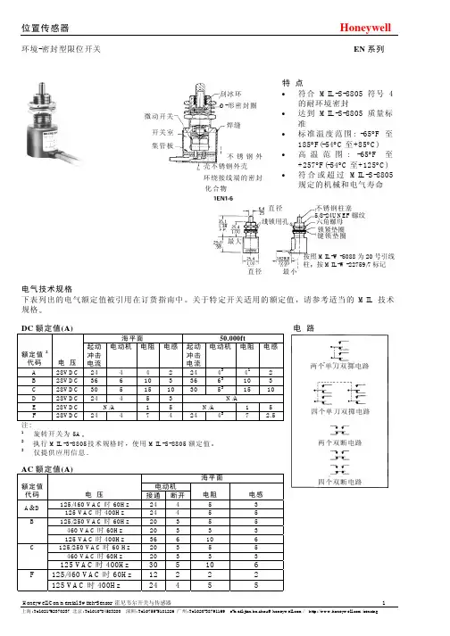
刮冰环 O-形密封圈微动开关焊缝开关室 集管板不锈钢外壳不锈钢外壳 环绕接线端的密封化合物特 点•符合MIL-S-8805符号4的耐环境密封•达到MIL-S-8805质量标准•标准温度范围: -65°F 至185°F(-54°C 至+85°C) •高温范围: -65°F 至+257°F(-54°C 至+125°C) •符合或超过MIL-S-8805规定的机械和电气寿命直径 不锈钢柱塞线锁用孔 六角螺母锁紧垫圈最大按照MIL-W-5088为20号引线柱按MIL-W-22759/7标记直径 最小电气技术规格下表列出的电气额定值被引用在订货指南中关于特定开关适用的额定值请参考适当的MIL 技术规格DC 额定值(A)电 路海平面 50.000ft额定值2代码 电 压 起动 冲击 电流 电动机 电阻 电感 起动 冲击 电流 电动机 电阻 电感A 28VDC 24 4 4 2 24 43 41 2B 28VDC 36 6 10 3 36 63 10 3C 28VDC 30 5 15 10 30 5315 10 D 28VDC 24 4 5 3 N/A E 28VDC N/A 1 5 N/A 1 5F 28VDC 24 4 7 4 24 437 2.5 注: 1旋转开关为5A 2执行MIL-3-8805 技术规格时使用MIL-S-8805额定值 3仅提供应用信息AC 额定值(A)海平面电动机 额定值 代码 电 压 接通 断开电阻 电感 125/460 VAC 时60Hz 24 4 5 3 A &D 125 VAC 时400Hz 24 4 5 5 125/250 VAC 时60Hz 20 3 5 5 460 VAC 时60Hz 20 3 3 3 B125 VAC 时400Hz 36 6 10 6 125/250 VAC 时60 Hz 20 3 5 5460 VAC 时60Hz 20 3 33C125 VAC 时400Hz 30 5 10 6125/460 VAC 时60Hz 12 2 2 2 F125 VAC 时400Hz 24 4 555/8-24UNEF 螺纹键锁垫圈两个单刀双掷电路四个单刀双掷电路两个双断电路四个双断电路终 端订货指南对终端设备作了具体规定通常引线为6ft长引线规格和军用技术规格说明在订货指南中安 装柱塞式执行器开关通过直径5/8 in 或15/32 in 的孔进行安装锁紧垫圈键锁垫圈与线锁六角安装螺母将开关锁定在其安装孔内旋转执行器开关通过直径15/32in 的孔进行安装线锁六角螺母和位于外壳顶部的定位销可防止开关旋转运 行柱塞式执行器用于在线启动刮冰环在每次动作时清洁执行器直径 5/8-24UNEF 螺纹球轴承柱塞式执行器可作任意方向上的动作刮冰环在每次动作时清洁执行器直径5/8-24滚轮柱塞执行器锁紧垫圈用于凸轮和滑动致动提升角度不超过20°滚轮在横向以45°增量进行调节刮冰环在每次动作时清洁执行器直径12.7/.50D ×3.0/.12 W 滚轮 5/8-24UNEF 螺纹旋转连接杠杆式执行器在旋转杠杆上配有螺杆用于正向起动旋转杠杆在任一方向上运行并在横向上作360°调节至任一位置螺杆在两个平面上旋转执行器没有弹簧返回但它直接受到起动设备运动的控制旋转滚轮杠杆式执行器用于凸轮和滑动致动提升角度大于30°这类执行器可提供有弹簧返回机构的以及可在顺时针和逆时针方向运行的两种设计该执行器在横向上作360°调节至任一位置滚轮由酚醛胶合板制成19,0/.75 D ×7,9/.31 W 滚轮15/32-32 NS螺纹0,0=mm说明: 0.00=in显示的尺寸仅供参考UNEF 螺纹15/32-32 10-32 NS 螺纹 UNF 螺纹MIL-S-8805性能认可的开关 EN 标准尺寸开关采购部件号接线端强度 N lbs 起动 方式 强度 N lbs 安装 套管 强度 Nm in lbs 振 动 冲 击 抗潮性 喷盐 爆炸 加速 密封 回弹性 (符号4) 1EN1-6 2EN1-6 3EN1-6 4EN1-6 MS24331-1 MS24331-2 MS24331-3 MS24331-4 66,7 15 133 301,7 15 在.060in(1,52mm) 双振幅时为10-58 Hz 在10gs 时为58-500 Hz 100gs .006s 锯齿形脉冲应用 测试应用 测试 应用 测试N/A 应用 测试31EN11-6 31EN1-6 32EN11-6 32EN1-6 33EN11-6 33EN1-6 34EN11-6 34EN1-6 MS21320-1 MS21320-2 MS21320-3 MS21320-4 MS21320-5 MS21320-6 MS21320-7 MS21320-8 66.7 1544,5 10 1,7 15 在.060in(1,52mm) 双振幅时为10-58 Hz 在10gs 时为58-500 Hz 100gs .006s 锯齿形脉冲应用 测试应用 测试 应用 测试N/A应用 测试41EN1-6 42EN1-6 43EN1-6 44EN1-6MS24420-1 MS24420-2 MS24420-3 MS24420-466,7 15- 1,7 15 在.060in(1,52mm) 双振幅时为10-58Hz 在10gs 时为58-500Hz 100gs.006s锯齿形脉冲应用 测试 应用 测试 应用 测试N/A应用 测试1EN75-R3 M8805/65-001 -44,5 10 1,7 15 在.060in(1,52mm) 双振幅时为10-70 Hz 在15gs 时为70-2000 Hz 高冲 击型“H”应用 测试 应用 测试 应用 测试N/A应用 测试1ENI-6 1ENI-S 1EN42-REN 标准尺寸开关订货指南 特性: O.F.-操作力; R.F.-释放力; P.T.-预行程; O.T.-超行程; D.T.-差动行程特 性外壳尺寸2电 路 执行器 接线端 电气 额定值 代码 产品目录号 O.F. N lbs . R.F . 最小 N in P.T. 最大 mm in O.T. 最小 mm in D.T. 最大 mm in 高度 mm in 直径 mm in重量 最大 g oz 更换安装用五金件包装.6两个 单极 双掷 电路柱塞球轴 承柱塞柱塞柱塞20号引线 MIL-W-22759/7同上螺钉4侧边5 插座AAAA1EN1-6 (MS24331-1) (8805/40)2001EN1-61EN1-S1EN42-R26,7-53,4 6-1226,7-53,4 6-1226,7-53,4 6-1226,7-53,4 6-12 17,8 4 17,8 4 17,8 4 17,8 41,02 .040 1,02 .040 1,02 .040 1,02 .0406,35 .250 6,35 .250 6,35 .250 6,35 .2500.51 .020 0.51 .020 0.51 .020 0.51 .02024,9 .980 24,9 .980 24,9 .980 24,9 .98025,4 1.025,4 1.025,4 1.0 58.43 2.3 2077.3 2077.3 99 3.5 221 7.81 1 3 3注: 1电气额定值见25页 2外壳直径与高度加上26页执行器的尺寸为整体尺寸 3不是外壳直径而是最大长度4这产品有4-48 NF ×.175 in 圆头螺钉与锁紧垫圈接线端用酚醛隔离层和环氧树脂作了良好隔离5这类产品有插脚式插座(配对连接器应向当地供应商订购) 6更换安装用五金连接组件产品目录号见33页 N=牛顿1EN43-R 2EN1-6 41EN1-621EN9-6 22EN9-6 42EN1-6 31EN1-6 32EN1-6EN标准尺寸开关订货指南特性: O.F.-动作力; R.F.-释放力; P.T.-预行程;O.T.-超行程; D.T.-差动行程特性外壳尺寸2电路执行器终端电气额定值1代码目录号O.F.NlbsR.F.最小NlbsP.T.最大mminO.T.最小mminD.T.最大mmin高度mmin直径mmin重量最大goz.更换安装用五金件包装4两个单刀双掷电路柱塞柱塞滚轮柱塞滚轮柱塞旋转滚轮杠杆旋转滚轮杠杆旋转连接杠杆旋转连接杠杆底部3插座18号引线MIL-W-22759/720号引线(MIL-W-22759/7)18号引线(MIL-W-22759/7)20号引线MIL-W-22759/718号引线MIL-W-22759/720号引线MIL-W-22759/718号引线MIL-W-22759/7ABABABAB1EN43-R2EN1-6(MS24331-2)(8805/40)21EN9-622EN9-631EN11-6(CW)(MS21320-1)(8805/48)31EN1-6(CCW)(MS21320-2)32EN11-6(CW)(MS21320-3)(8805/48)32EN1-6(CCW)(MS21320-4)(8805/48)41EN1-6(MS24420-1)42EN1-6(MS24420-2)(8805/49)26,7-53,46-1226,7-53,46-1226,7-53,46-1226,7-53,46-121,4-2,8Nm最大12-25in.lb.1,4-2,8Nm最大12-25in.lb.0,34Nm最大3in.lb.0,57Nm最大5in.lb.17,8422,8517,8422,251,0Nm9in.lb.1,0Nm9in.lb.--1,02.0401,27.0501,02.0401,02.04013’’20’’--6,35.2506,35.2506,35.2506,35.25032’’25’’--0,51.0200,89.0350,51.0200,75.0304’’最大6’’最大12’’最大12’’最大53,32.138,11,524,9.98038,11,553,62.1168,62.725,4142,21.6625,41,038,11,525,41,038,11,525,41.038,11,525,41.038,11.52047.21565.52528.938,313.52699.5368132137.52207.753144555555注:1电气额定值见25页2外壳直径与高度加上26页执行器的尺寸为整体尺寸3这些产品有插脚式插座(配对连接器应向当地供应商订购)4更换安装用五金连接组件见33页N=牛顿5EN1-6 25EN9-6 3EN1-6 23EN9-6 33EN1-64EN1-6 24EN9-6 34EN1-6 44EN1-6特性: O.F.-动作力; R.F.-释放力;EN标准尺寸开关订货指南P.T-预行程; O.T-超行程; D.T.-差动行程特性外壳尺寸2电路执行器终端电气额定值1代码目录号O.F.Nlbs.R.F.最小NlbsP.T.最大mminO.T.最小mminD.T.最大mmin高度mmin直径mmin重量最大goz.更换安装用五金件包装3四个单刀双掷电路(电路图见25页)柱塞滚轮柱塞20号引线(MIL-W-5086)20号引线(MIL-W-5086)AA5EN1-625EN9-626,7-53,46-1226,7-53,46-1217,8417,841,02.0401,02.0406.35.2506.35.2500.76.0300.76.03030,51.230,51.238,11.538.11.534612.236012.734两个双制动电路柱塞滚轮柱塞旋转滚轮杠杆18号引线MIL-W-22759/718号引线MIL-W-508618号引线MIL-W-22759/7CCC3EN1-6(MS24331-3)(8805/40)23EN9-633EN11-6(CW)(MS21320-5)(8805/48)33EN1-6(CCW)(MS21320-6)(8805/48)26,7-53.46-1226,7-53.46-121,4-2,8Nm12-25in.lb.22,2522,250,9Nm8in.lb.1,52.0601,52.06015°6,35.2506,35.25030°0,89.0350,89.0355°33,31.3133,31.31622.4438,11.538,11.538.11.52418.525592699.51455四个双制动电路柱塞滚轮柱塞旋转滚轮杠杆旋转连接杠杆18号引线MIL-W-22759/718号引线(MIL-W-5086)18号引线MIL-W-22759/718号引线MIL-W-22759/7CCCC4EN1-6(MS24331-4)(8805/40)24EN9-634EN11-6(CW)(MS21320-7)(8805/48)34EN1-6(CCW)(MS21320-8)(8805/48)44EN1-6(MS24420-4)(8805/49)26,7-53,46-1226,7-53,46-121,4-2,8Nm12-25in.lb.1,1Nm最大10in.lb.22,2522,250,9Nm8in.lb.-1,78.0701,78.07015°-6,35.2506,35.25030°-1,14.0451,14.04510°20’’43,21.743,21.771,62.8245,71.838.11.538.11.538.11.538.11.5368133681343915.545115.914555注:1电气额定值见26页.2外壳直径与高度加上26页执行器的尺寸为整体尺寸3更换安装用五金连接组件见33页.N=牛顿IEN 194-S (外观类似,配有螺钉接线端子)1EN51-6 1EN61-6 1EN75-R 1EN76-R 1EN75-R3 21EN75-R1 21EN75-2 1EN231-6EN特殊要求开关订货指南特性: O.F.-动作力; R.F.-释放力;P.T-预行程; O.T-超行程; D.T.-差动行程特性特殊2要求执行器终端电路电气额定值1代码目录号O.F.Nlbs.R.F.最小mminP.T.最大mminO.T.最小mminD.T.最大mmin重量最大goz.更换安装用五金件包装3高速度起动柱塞 20号引线(MIL-W-22759/1)(2)单刀双掷A 1EN231-626.7-53.46-1217.841.02.0405.84.2300.51.0202077.33低作用力动作柱塞 20号引线(MIL-W-5086)(2)单刀双掷A 1EN51-613.3-26.73-68.921.02.0406.35.2500.51.0202137.53增加超行程柱塞 20号引线(MIL-W-5086)(2)单刀双掷A 1EN61-626.7-53.46-1217.841.02.04012.7.5000.51.02022783增加的超行程柱塞螺钉 (2)单刀双掷A 1EN194-S26.7-53.46-1217.840.38-1.02.015-.04021.8.8600.51.02011347高冲击柱塞底部插座 (2)单刀双掷A 1EN75-R26.7-53.46-1217.841.02.0406.35.2500.51.02019878高冲击柱塞侧边插座 (2)单刀双掷A 1EN76-R26.7-53.46-1217.841.02.0406.35.2500.51.02022788高冲击柱塞底部插座 (2)单刀双掷D 1EN75-R3(M8805/65-001)26.7-53.46-1217.841.02.0406.35.2500.51.02019878高冲击滚轮柱塞底部插座 (2)单刀双掷A 21EN75-R126.7-53.46-1217.841.02.0406.35.2500.51.0202047.211高冲击滚轮柱塞20号引线(MIL-W-22759/7)(2)单刀双掷A 21EN75-R226.7-53.46-1217.841.02.0406.35.2500.51.0202077.311 注:1电气额定值见25页2产品仅是满足特殊应用要求已开发的几个产品设计如果你有类似或不同的特殊要求, 请与MICRO SWITCH办事处联系, 以获得满足要求的开关3更换安装用五金连接组件见33页N=牛顿特殊要求开关的说明高速度起动该开关被设计成能承受接近“锤击”般的起动如同偏心自锁机构中新存在的“锤击”一样开关的尺寸可与标准目录号1EN1-6互换低作用力动作该开关内特殊的弹簧结构将通常的6至12磅(26,7至53,4N)的EN动作力降低到3至6磅(13,3至26,7N)该开关的尺寸也可与标准尺寸1EN1-6进行互换低动作力的600EN系列开关具有3至6磅(13,3至26,7N)的动作力增加超行程开关上的较长柱塞和套管将EN超行程能力从通常的.250in扩展至.860(6.35至21.8mm)较长套管还允许追加对柱塞位置进行调节高冲击产品目录号1EN75-R3 (M8805 /65-001)达到了MIL –S-8805 的质量标准包括高冲击等级H其它为高冲击应用场合额定的开关包括如同1EN75-R3中所用的相同柱塞机构和内部开关设计并要求它符合同样的要求这些产品目录号终端是:1EN75-R DM-9601-7R-1DDeutch插座1EN75-R3 GS02-16S-1P-003Cannon插座1EN76-R DM-9601-7P-1DDeutch插座21EN75-R1 G S02-16S-1P-003Cannon插座21EN75-2 MIL-W-22759/72 ft 20号引线MICRO SWITCH不提供与这些产品配对的连接器位置传感器EN 系列环境-密封型限位开关微型 标准特 点•符合或超过MIL-S-8805中规定的机械和电气寿命 •密封定义: 耐环境回弹性符合MIL-S-8805符号4 •军用技术规格: MIL-S-8805 •温度范围: -67°F 至+185°F (-55°C 至+85°C)电气额定值 参阅25页微型开关微型EN 开关满足了对尺寸小重量轻不牺牲性能或电气能力的需求这类开关与标准规格EN 开关具有相同的结构密封和材质400EN型开关虽然直径小重量轻但它直接可与标准规格EN 开关的对应部件进行互换微型开关的外壳直径要小.312in(7,92mm)开关重量要轻1/2盎司(14,2g)MIL-S-8805开关 EN 微型开关目录号 采购 部件号 接线端强度 N lbs. 起动方式强度 N lbs. 安装 套管 强度 Nm in.lbs . 振 动冲 击 防湿性喷 盐 爆 炸 加 速 密封 回弹性 (设计4) 402EN1-6 404EN1-6MS21321-1 MS21321-266,7 15133 301,7 15在.060in(1,52mm)D.A.1时为10-70Hz在15gs 时为70-2000 Hz 100gs .006s 锯齿形 脉冲应用 测试应用 测试应用 测试N/A应用 测试602EN1-6 604EN1-6 622EN1-6 624EN1-6 602EN222-6 604EN222-6 622EN222-6 624EN222-6 MS27240-1 MS27240-2 MS27240-3 MS27240-4 MS27240-5 MS27240-6 MS27240-7 MS27240-866,7 15 44,5 10 1,7 15 在.060in(1.52mm)D.A.11时为10-70Hz在15gs 时为70-2000 Hz100gs .006s 锯齿形 脉冲应用 测试应用 测试应用 测试N/A应用 测试注: 1.D.A.=双振幅或移位402EN1-6 602EN1-6直径钢柱塞5/8-24 UNEF 螺纹 直径 线锁用孔(6)符合MIL-W-22759/7 (5)符合MIL-W-22759/7 的20号引线 的20号引线按MIL-W-5088标记 按MIL-W-5088标记 最小 最小六角螺母锁紧垫圈键锁紧垫圈线锁用孔 15/32-UNS-2A 螺纹 六角螺母 锁紧垫圈 键锁紧垫圈钢柱塞位置传感器EN系列环境-密封型限位开关442EN1-6 404EN1-6 444EN1-6 622EN1-6 604EN1-6 602EN602-6特性: O.F.-动作力; R.F.-释放力;EN标准规格开关订货指南P.T-预行程; O.T-超行程; D.T.-差动行程特性外壳尺寸1电路执行器电气额定值代码目录号O.F.Nlbs.R.F.最大Nlbs.P.T.最大mminO.T.最小mminD.T.最大mmin高度mmin直径mmin重量goz.更换安装用五金件包装3两个单刀双掷电路柱塞旋转连接杠杆FF402EN1-6(MS21321-1)(8805/39)442EN1-626,7-53.46-1234Nm最大3in.lbs.17,84-1,02.040-6,35.250-0,51.02012’’24,9.98025,41.017,5.68817,5.6882047.22077.319柱塞 F 404EN1-6(MS21321-2)(8805/39)26,7-53,46-1217,841,02.0406,35.2500,51.02030,51.225,41.035412.51 四个单刀双掷电路旋转连接杠杆F 444EN1-6 34Nm最大3in.lbs.- - - 12’’30.21.1925,41.0340126 柱塞 FE602EN1-6(MS27240-1)(8805/43)602EN222-6(MS27240-5)(8805/43)26,7-53,46-1217,841,02.0403,18.1250,51.02025,41.017,5.6881766.222 两个单刀双掷电路滚轮柱塞FE622EN1-6(MS27240-3)(8805/43)622EN222-6(MS27240-7)(8805/43)26,7-53,46-1217,841,02.0403,18.1250,51.02025,41.017.5.6882047.21010柱塞 FE604EN1-6(MS27240-2)(8805/43)604EN222-6(MS27240-6)(8805/43)26,7-53,46-1217,841,02.0403,18.1250,51.02030,51.225,41.035412.522 四个单刀双掷电路滚轮柱塞FE624EN1-6(MS27240-4)(8805/43)624EN222-6(MS27240-8)(8805/43)26,7-53,46-1217,841,02.0403,18.1250,51.02030,51.225,41.035412.510两个单刀双掷电路直径.125的柱塞F 602EN602-6 8,9-17,82-44,410,38.015±.0106,35.250,051.02025.41.017,5.6881706.02 注:1外壳直径与高度加上此页或26页执行器尺寸为开关总尺寸2这里列出的所有微型EN限位开关按照MS22759-7都有6ft长(1,8m)的20号引线按MIL-W-5088标记关于变化情况请联系MICRO SWITCH3更换安装用五金连接套件的产品目录号见33页N=牛顿600EN执行器尺寸400EN执行器尺寸与26页上所示的标准规格EN系列的尺寸相同直径15/32-32NS螺纹直径9,5/.38 D×3,0/.12W 滚轮15/32-32 NS螺纹位置传感器EN 系列环境-密封型限位开关EN 开关更换部件的订货指南说 明 用 于:6PA30滚轮杠杆臂 30EN 系列6PA316PA357连接杠杆臂只提供螺杆40EN 系列6PA326PA202滚轮杠杆臂滚轮杠杆臂 1EN 和1HE 系列600EN 和600HE 系列15PA10415PA105滚轮导轨和锁紧环滚轮导轨和锁紧环21EN 422/424EN 系列(5/0”套管)622/624EN 系列(15/32”套管)15PA13715PA107只提供锁紧环只提供锁紧环21EN 422/424EN 系列(5/0”套管)622/624EN 系列(15/32”套管)19PA819PA9军用型安装用五金连接件 军用型安装用五金连接件 1EN 系列(5/0”套管)600EN 系列(15/32”套管)更换安装用五金连接套件盒请见前几页的EN 开关订货指南(产品目录号栏和右侧栏), 以便相互对照开关/安装用五金连接套件更换安装用五金件包装 目录号 更换安装用五金件包装 目录号 1 19PA8 7 19PA120-EN 2 19PA9 8 19PA121-EN 3 19PA78-EN 9 19PA122-EN 4 19PA115-EN 10 19PA123-EN 5 19PA117-EN 11 19PA124-EN 6 19PA119-EN1可提供其它套件直径 最小环境-密封型限位开关EN 系列EN 开关安装尺寸(仅供参考) 标准规格EN 开关1EN75-R 1EN75-R3直径 钢柱塞 直径 钢柱塞线锁用孔 1-20 UNEF 螺纹 1-20 UNEF 螺纹六角螺母 六角螺母 锁紧垫圈 锁紧垫圈键锁紧垫圈 键锁紧垫圈最大直径 直径1EN76-R 21EN75-R1自由位置线锁用孔 钢柱塞和套管 12,7/.50×3,0/.12 W直径 1-20 UNEF 螺纹 钢滚轮键槽 滚轮导轨和锁紧环 锁紧垫圈 六角螺母 键锁紧垫圈 锁紧垫圈六角螺母键槽最大直径1EN51-61EN231-6 21EN75-2直径 钢柱塞 线锁用孔5/8-24 UNEF 螺纹线锁用孔 六角螺母锁紧垫圈键锁紧垫圈最大 键槽(6)符合MIL-W-5086 直径 最小 的20号引线 直径 最小按MIL-W-5088S 标记1EN61-6 600EN 执行器直径 直径 钢柱塞 15/32-32 NS5/8-24 UNEF 螺纹 螺纹六角螺母锁紧垫圈最大0,0=mm图例: 0.00=in线锁用孔 键锁紧垫圈 1-20 UNEF 螺纹 12,7/.50D × 3,0/.12 W 钢滚轮 滚轮导轨和锁紧环 六角螺母 锁紧垫圈键锁紧垫圈1-20 UNEF 螺纹键锁紧垫圈线锁用孔直径9.5/.38D ×3.0/.12W 滚轮 15/32-32NS 螺纹 符合MIL-W-5086 的20号引线 按MIL-W-5088标记。
An AutoRAE2 system configuredwith all cradle types.The AutoRAE 2 Automatic Test and Calibration System for Honeywell RAE Systems portable monitors makes instrument testing and calibration compliance as easy as pressing a button. Simply cradle the monitor, and the system takes care of calibration, testing, and battery recharging.The AutoRAE 2 system is flexible and modular, and can be configured to efficiently meet your calibration and records management requirements. An AutoRAE 2 system can be as simple as a single cradle deployed in stand-alone mode to calibrate one instrument at a time, or as powerful as a networked, controller-based system supporting 10 instrument cradles and 5 distinct calibration gases or gas mixtures.• Easy, one-touch bump testing, calibration, charging, and records management• Supports a wide variety of gases, including exotics• Optimized for field use—does not require a computer to operate • Firmware-upgradeable to protect your investmentIndustries• Oil and Gas • Industrial • Environmental • Fire Service • National SecurityAutoRAE 2Automatic Test and Calibration System• Automatic testing, calibration, charging system• Deployable as astand-alone cradle or a controller-based system with up to 10 cradles• Controller with a large, color LCD display • Networking capability • Up to 5 calibration gas cylinders can beconnected at the same time*• Automatic instrument FW update option • Instruments datalogging filerecorded automatically on controller SD card • Bench-top orwall-mounted use• Instruments supported:- ToxiRAE Pro Series - QRAE3, MicroRAE - MultiRAE Series (except diffusion model)• Single Cradle for all Handheld PID, QRAE 3 and ToxiRAE Pro family instruments• Device Management with Honeywell SafetySuiteFEATURES & BENEFITSThe high-resolution color displayon the controller provides a rich,intuitive user experience.* Supported only on configurations that include the AutoRAE 2 ControllerAutoRAE 2Automatic Test and Calibration SystemORDERING INFORMATIONORDERING OPTIONSRefer to the Portables Pricing Guide for a complete list of AutoRAE 2 components and accessoriesDatasheet_AutoRAE 2_DS-1083-07_EMEA-EN 04/18 ©2018 Honeywell International Inc.For more information Europe, Middle East, Africa Life Safety Distribution GmbHTel: 00800 333 222 44 (Freephone number)Tel: +41 44 943 4380 (Alternative number)Middle East Tel: +971 4 450 5800 (Fixed Gas Detection)**************************Americas Honeywell Analytics Distribution Inc.Tel: +1 847 955 8200Toll free: +1 800 538 0363***********************Honeywell RAE Systems Phone: +1 408 952 8200Toll Free: +1 888 723 4800Asia PacificHoneywell Analytics Asia Pacific Tel: +82 (0) 2 6909 0300India Tel: +91 124 4752700China Tel: +86 10 5885 8788-3000**************************Technical ServicesEMEA:**********************US:***************************AP:***************************/SafetySuiteDevice Management withHoneywell SafetySuite。
霍尼韦尔HCS01多功能运动传感器三大基本功能/及应用:◆ 确定方向:姿态补正的三轴罗盘,可用于GPS盲区推估◆ 姿态控制:加速度传感器能感知姿态,可用于姿态控制◆ 高度计:气压传感器可用于测量高度传感器高度集成,全数字量输出,使用简单方便推荐应用霍尼韦尔上海办事处上海市长宁区遵义路100号虹桥上海城B座23楼电话:+86-21-62370237霍尼韦尔广州办事处广州市海珠区滨江中路308号海运大厦15楼电话:+86-20-84101800霍尼韦尔(中国)有限公司传感与控制部合七为一(三轴方向 + 三轴姿态+高度)◆ 小尺寸 (6.5 mm X 6.5 mm X 1.2 mm)◆ I2C 数字通讯接口◆ 内置ASIC 数字补偿芯片和EEPROM 存储器◆ 方向输出◆ 姿态输出◆ 海拔高度输出◆ 湿度输出(需要外置湿度电阻)三轴磁阻传感器HCS01传感器外形尺寸 6.5 毫米 X 6.5 毫米 X 1.2 毫米通讯接口I2C 芯片外形QFN 引脚数量24 脚模数转换16-bit A/D外挂传感器接口接口适合外挂湿度电阻电气特性供电电压数字供电 1.8 V 供电电压模拟供电 3.3 V储存温度-40℃ 至 105℃运行环境温度-20℃ 至 80 ℃静态消耗电流30 微安动态消耗电流 6 毫安I2C 接口及数字输出SCL 时钟频率400 KHz低电平输入电压 (V IL )0.3 伏(数字供电)高电平输入电压(V IH )0.7 伏(数字供电)低电平输出电压 (V oL )0.1伏(数字供电)高电平输出电压 (V oH )0.9 伏(数字供电)磁阻传感器特性磁通量测量范围+/-120uT 磁通量测量限制范围+/-500uT 方位角精度+/-3 度加速度传感器特性加速度检测范围+/- 2g 倾斜测量范围+/-90 度倾斜角精度+/- 3 度气压传感器特性压力测量范围710 至 1062 hPa 海拔高度测量范围100 至 2000米海拔高度测量精度+/-10 米湿度传感器特性测量范围20 至 90 %RH 可测量的温度范围 5 至 45 ℃相对湿度精度+/-5 %RH 湿度响应时间(条件:30%RH 转换 90%RH 风速1.2厘米/秒)3.5 分钟。
电子罗盘模块按照NMEA格式,通过RS232/485串口提供航向输出(横滚、俯仰、偏航)采用Honeywell公司的固态磁阻传感器,具有快速的响应时间至20Hz,航向精度为0.5˚ ,分辨率为0.1˚。
快速响应时间小体积低功耗高精度宽的倾斜角度对铁磁物性金属进行补偿使用固态磁传感器提高了响应速度,和万向架固定式的磁通门传感器相比提高了数据更新速度。
仅为一块线路板,重量小于57克,体积为83x25x22mm,铝外壳封装。
功耗小于25mA,可长时间电池供电0.5˚ 航向精度,分辨率0.1˚ ,可适用于严格定向的应用场合。
倾斜角度为±40˚ ,适合于广泛的要求精确的应用通过对因环境中存在铁磁性金属而对地磁场造成的扭曲的补偿,提高精度。
下表显示,9针插头引脚排列,电源可以为调制的5V ,或不调制6—15V ,只有#9针或#8针中的一个,可由给定连接方法连接。
见以下:接口信号描述通信HMR3000 用简单的ASCII 字符与外部主控制器,通过 RS-232 或 RS-485 通讯。
ASCll 码的发送和接收,使用1个起始位,8个数据位(先是LSB,MSB 总为0) ,无奇偶位,和一个停止位,波特率可设置为1200,2400,4800,9600,19200或38400,HMR3000 对所有收到的带校验码的有效输入作反应。
罗盘输出HMR3000输出三种NMEA 标准格式(HDG,HDT 和XDR),三种专用格式(HPR,RCD 和CCD),及一个 ASCll 码航向输出,用于数据显示。
HDG,HDT 和HPR 是最通用格式。
$HCHDG 航向、偏差角、磁偏角$HCHDG, 85.5, 0.0, E, 0.0, E*77$HCHDT,航向、对(True)$HCHDT,271.1,T*2C$PTNTHPR,航向、俯仰和横滚$PTNTHPR,Heading,Heading Status,Pitch,Pitch Status,Roll,Roll Status*hh<cr><lf>$PTNTHPR,85.9,N,-0.9,N,0.8,N*2C名称TxD/B RxD/A GND 6-15V 5VOper/Calib(2)Run/Stop(2)Ready/Sleep(2)Cont/Reset(2)入/出Out In In In In In In In In引脚235981647描述RS-232 发送/ RS-485RS-232 接收 / RS-485电源/信号地未调理的电源电压输入调理的电源电压输入Operate/Calibrate (3) input (open=Operate)Run/Stop (3) input (open=Run)Ready/Sleep (3) input(open=Ready)Continue/Reset (3) input (open=Continue)(典型值)---6-155 ± 5%0-50-50-50-5(最小值)(1)-18-1800-20-20-20-20单位Vdc VdcVdc Vdc Vdc Vdc Vdc Vdc(最大值)(1)1818307.520202014(1) 绝对最大值(2) 沉电流:200µA (典型值), 400mA(最大值)(3) 开路输入 =高电平HMR3000 连线图——计算机RS232 到 HMR3000订货指南HMR3000-Demo-232*.....RS232HMR3000-D00-232..........RS232.........NoneHMR3000-D21-232..........RS232.........Extended BaseHMR3000-D00-485..........RS485.........NoneHMR3000-D21-485..........RS485.........Extended Base*Development Kit includes one module in alu minum enclosure, cablingwith power supply, demonstration software for PC running Windows™and User’s Manual.数值<0.5˚<1.5˚± 0.3˚0.1˚degrees/mils ±40˚±0.4˚±0.6˚±0.2˚0.1˚degree/mils ±1.0 Gauss (最大值)1 mGauss 5.0 Vdc 调理电压6~15Vdc 未调理电压35 mA@6 Vdc13 mA 2.0 mA RS-232RS-4851200 to 38400 bps NMEA 0183连续滤波0.75 oz (22g)3.25 oz (92g)1.2 x 2.95 x 0.7601.5 x 4.2 x 0.88-20 to 70˚C -35 to 100˚C 30 英寸高落下20~2000Hz Random 2 hrs/axisIPC6012IPC610航向角俯仰和横滚磁场电气接口物理环境制造指标1. 航向精度是假设地球磁体只有硬铁干扰,已通过标定进行补偿2. 标定值3. 由设计参数保证4. 典型5. 迟到或超过*器件方向角不超过75˚在工作或贮存时——可引起短暂的精度损失。
Technical NoteSPI Communication with Honeywell Digital Output Pressure SensorsSensing and Control1.0 IntroductionThe Serial Peripheral Interface (SPI) is a simple bus system for synchronous serial communication between one master and one or more slaves. It operates either in full-duplex or half-duplex mode, allowing communication to happen in either both directions simultaneously, or in only one direction. The master device initiates an information transfer on the bus and generates clock and control signals. Slave devices arecontrolled by the master through individual slave select lines and are active only when selected.Honeywell pressure sensors with SPI output operate in half-duplex mode only, with data transfer from the slave to the master (Figure 1). For this data transmission three lines need to be used:1. Slave Select (SS)2. Signal Clock (SCLK)3. Master In - Slave Out (MISO)These three bus lines are all unidirectional. SCLK and SS and are controlled by the master while MISO is controlled by the slave.2.0 Data Transfer with SPI Output Pressure SensorsStarting communication with Honeywell SPI output pressure sensors begins by deasserting the SS line. At this point, the sensor is no longer idle, and will begin sending data once a clock is received.Honeywell digital output pressure sensors are configured for operation such that data on the MISO line will transition during the falling edge of clock pulses. This means that the data on MISO should be sampled by the master device during the rising edge of the clock pulse.Figure 2 shows an example of a 1 byte data transfer from the slave to the master. In this example, the data 101 (01100101 binary, or 65 hex) would be the result of the read.Figure 2. Example of a 1 Byte SPI Data Transfer withOnce the clocking begins, Honeywell digital output pressure sensors are designed to output up to 4 bytes of data, depending on the sensor options and the needs of the application. In all cases, the first two data bytes are thecompensated pressure output, along with sensor status bits. The third and fourth bytes are for optional compensated temperature output.2.1 Pressure ReadingTo read out a compensated pressure reading, the master generates the necessary clock signal after activating thesensor with the slave select line. The sensor will transmit up to 4 bytes of data – the first two bytes containing thecompensated pressure output, and the second two bytescontaining the optional compensated temperature output. The master can terminate the communication by stopping the clock and deactivating the slave select line. Examples of the communication are shown in Figure 3.SPI Communication with Honeywell Digital Output Pressure Sensors2 Honeywell Sensing and Controlbytes of data. The information contained in these bytes is non-corrected data, and should not be used.2.2 Temperature ReadingThe optional corrected temperature data can be read out with either 8 bit or 11 bit resolution. By reading out the third byte of data from the sensor, the 8 bit compensated temperature value can be read. Further, by reading out the fourth byte of data, the complete 11 bit optional compensated temperature value can be read. The 8 bit value gives an approximate 0.8 ºC resolution, while the 11 bit value gives an approximate 0.1 ºC resolution.When reading the full 11 bit resolution temperature output, the 5 least significant bits of the fourth data byte are “Do Not Care ” and should be ignored.2.3 Status BitsHoneywell digital output pressure sensors offer both standard and optional diagnostics to ensure robust system operation in critical applications. The diagnostic states are indicated by the first two Most Significant Bits of data byte 1.Four diagnostic states are indicated by the 2 status bits (Table 1).This mode should not be seen during normal operation.Standard diagnostics for Honeywell digital output pressure sensors consists of an EEPROM (Electrically ErasableProgrammable Read-Only Memory) signature used to validate the EEPROM contents during startup. In the event that any EEPROM contents change after calibration, a diagnostic condition will be flagged.Optional diagnostics for Honeywell digital output pressure sensors consist of:Loss of sense element connection Short circuit of sense elementSPI Communication with Honeywell Digital Output Pressure SensorsHoneywell Sensing and Control 3When the two status bits are “11”, one of the above mentioned diagnostic faults is indicated.When the status bits read “10”, “s tale” data is indicated , this means that the data that already exists in the sensor’s output buffer has already been fetched by the master, and has not yet been updated with the next data from the current measurement cycle. This can happen when the master polls the data quicker than the sensor can update the output buffer.(Please contact Honeywell Customer Service with questions regarding the availability of optional digital output pressure sensor diagnostics.)3. 0 Calculation of the Pressure from the Digital OutputFor Honeywell digital output pressure sensors, the output of the device can be expressed by the transfer function of the device as shown in Equation 1.Equation 1: Pressure Sensor Transfer Function Output (OutputRearranging this equation to solve for Pressure, we get Equation 2:Equation 2: Pressure Output Function max Pressure (Output (Pressure (OutputWhere:Output max = output at max. pressure [counts] Output min = output at min. pressure [counts]Pressure max = max. value of pressure range [bar, psi, kPa, etc.] Pressure min = min. value of pressure range [bar, psi, kPa, etc.] Pressure = pressure reading [bar, psi, kPa, etc.] Output = digital pressure reading [counts]As an example, the pressure will be calculated for a -1 psi to 1 psi differential sensor with a 10% to 90% calibration and a pressure output of 1657 (decimal) counts:Output max = 14745 counts (90% of 214counts or 0x3999)Output min = 1638 counts (10% of 214counts or 0x0666) Pressuremax= 1 psiPressure min = -1 psiPressure = pressure in psi Output = 1657 counts)1()163814745())1(1()16381657(Pressure)1(13107)2()19(Pressure )1(1310738Pressure)1()002899.0(Pressure997.0Pressure psi 4.0 Calculation of Optional Temperature from the Digital OutputFor Honeywell digital output pressure sensors with the optional compensated temperature output, the output can be converted to degrees C using Equation 3:Equation 3: Temperature Conversion Function 50200Output C)(If the 8 bit temperature output is used, the data must first be shifted left by 3 bits and have the 3 Least Significant Bits set to “0’s ” for the equation to work.As an example, the optional compensated temperature output will be calculated for a sensor with an 8 bit temperature output of 255:Step 1: Left shift the above 8-bit value by 3 places and append the 3 LSBs with 0s:Digital Temperature Output (8 – bit) = 255 = 11111111b 11111111000b = 2040Step 2: Use the adjusted value and plug into Equation 3:5020020472040e Temperatur149.31 e Temperatur ºCAs a second example, the optional compensated temperature output will be calculated for a sensor with an 11 bit temperature output of 1456:Step 1: Plug the digital temperature output value into Equation 3:5020020471456e Temperatur26.92 e Temperatur ºCSPI Communication with Honeywell Digital Output Pressure SensorsSensing and ControlHoneywell1985 Douglas Drive NorthGolden Valley, MN 55422 /sensing 008202-3-ENMay 2012Copyright © 2012 Honeywell International Inc. All rights reserved.5.0 Timing and Level ParametersPERSONAL INJURYDO NOT USE these products as safety or emergency stopWARRANTY/REMEDYHoneywell warrants goods of its manufacture as being free of defective materials and faulty workmanship. Honeywell’s standard product warranty applies unless agreed to otherwise by Honeywell in writing; please refer to your order acknowledgement or consult your local sales office for specific warranty details. If warranted goods are returned to Honeywell during the period of coverage, Honeywell will repair or replace, at its option, without charge those items it finds defective. The foregoing is buyer’s sole reme dy and is in lieu of all other warranties, expressed or implied, including those of merchantability and fitness for a particular purpose. In no event shall Honeywell be liable for consequential, special, or indirect damages.While we provide application assistance personally, through our literature and the Honeywell web site, it is up to the customer to determine the suitability of the product in the application.Specifications may change without notice. The information we supply is believed to be accurate and reliable as of this printing. However, we assume no responsibility for its use.WARNINGMISUSE OF DOCUMENTATIONThe information presented in this technical note sheet is for reference only. DO NOT USE this document as aproduct installation guide.Complete installation, operation, and maintenanceinformation is provided in the instructions supplied witheach product.Failure to comply with these instructions could result in death or serious injury.SALES AND SERVICEHoneywell serves its customers through a worldwide network of sales offices, representatives and distributors. For application assistance, current specifications, pricing or name of the nearest Authorized Distributor, contact your local sales office or:E-mail:*********************Internet: /sensingPhone and Fax:Asia Pacific +65 6355-2828+65 6445-3033 FaxEurope +44 (0) 1698 481481+44 (0) 1698 481676 FaxLatin America +1-305-805-8188+1-305-883-8257 FaxUSA/Canada +1-800-537-6945+1-815-235-6847+1-815-235-6545 Fax。
前言本说明讨论如何用SS400/SS4/SS1系列开关霍尔传感器替代直流电动机中的机械换相。
该系列传感器价格低,其动作及释放点的高斯数很低(@25℃±40℃),可作为一种低成本的磁性换相器使用。
它们与低功耗半导体配合使无刷直流电机在电机市场上极具价格竞争力。
工作原理无刷直流电机基本上与带电刷电机的内部构造相同。
电源施加于转子线圈,永久磁铁是转子的一部分。
依电动机设计方式的不同而确定旋转件是在内部还是在外部。
直流电动机的电刷和换相器也由位置传感器和电子开关所代替。
扭矩,即产生运动的力,在直流电机上是通过永久磁场与线圈电流相互作用产生。
在有刷电机中,换相器切换电枢线圈,从而提供了适当的磁通量和转子电流互相感应。
而在无电刷电机中,一个位置传感器即可通过逻辑电路和驱动电路感知旋转磁铁的位置,并激励正确的线圈。
典型驱动电路当今社会,有多种无刷直流电机正在广泛应用。
图1是一个三相8极电动机,使用双极霍尔效应传感器。
旋转的永久磁铁在传感器面前运动从而使传感器改变状态。
传感器在每次南极通过时开始工作。
图2为三个传感器的输出图,这三个传感器在无刷电机中的电角度间隔为30度。
在8极磁铁无刷电机中,相邻南极间的电角度为90度。
当三个传感器放置间隔角度为30度时,第一个传感器动作于30度,第二个为60度,第三个为90度。
北极通过传感器时,传感器会释放。
每个旋转8极磁铁的北极与相邻南极的角度为45度。
“动作”完毕后,每个传感器都会在45度角后释放。
三个传感器的输出,作为轴位置编码器使用。
传感器将磁铁位置和极性信息,提供给逻辑电路,再控制三极管的开闭,三极管的排列为“H ”型桥式。
图1 典型无电刷直流电动机主要零件图2 传感器的工作SS400/SS4/SS1低高斯双极霍尔效应传感器图3是一个使用6个三极管和三个霍尔效应传感器的驱动电路样例。
每一对三极管被开启或关闭,根据旋转磁铁的位置决定。
根据磁铁位置上,转子线圈的电流有相应的频率和时间。
Honeywell传感器广州南创房工Honeywell是一家财富100强公司发明和生产技术,以解决与全球宏观趋势,如安全性,安全性和能源的严峻挑战。
Honeywell传感器全球约132,000名员工,其中包括超过19,000名工程师和科学家,Honeywell传感器的产品在多个国家设立了国外办事处及售后服务中心,并在中国设立了广州南创传感器事业部,为Honeywell传感器提供最佳的服务与解决方案。
有质量,交货,价值,和美国Honeywell传感器做的一切技术的不懈重点。
Honeywell传感器的能力不断提高,来自成功实现两个看似竞争的一次任务 - 生产力和经济增长。
Honeywell传感器公司的核心内部业务流程,传动效率和服务质量。
促成带来世界一流的产品和服务更快地推向市场和更具成本效益自动化和控制解决方案美国Honeywell的环境控制,生命安全,安全,遥感,扫描,移动产品,以及建筑和工艺解决方案是在工作中,在150万个家庭,10万座建筑物,5000工业设施,以及数以百计的全球天然气和电力公用事业。
美国Honeywell的产品和解决方案,使客户能够捕获更多和更好的数据,更快的速度和整个无线景观,提高生产率,安全性和安全性,推动更好的决策,并降低了成本。
航天美国Honeywell流量传感器的航空航天产品和服务用于全球几乎所有的商业和商务飞机经营的今天,以及国防和空间应用。
美国Honeywell提供综合航空电子系统,发动机,系统和服务解决方案,认真听取美国Honeywell的客户和重点放在最能满足他们的需求,使飞行更安全,更可靠,更高效,更具成本效益的技术。
高性能材料和技术以开发和制造先进的材料和工艺技术,是人每天使用,以减少温室气体排放,阻止子弹,使生产的绿色燃料,增加炼油能力,加速药物发现,和保护药品的全球领先地位。
美国Honeywell的先进材料制造尼龙至计算机芯片医药包装产品,以及工艺技术由霍尼韦尔公司的UOP公司的形式大部分世界炼油厂的基础有效地生产汽油,柴油,喷气燃料,石油化工和生物燃料开发的关键。
交通运输系统交通系统是一个世界级的技术和汽车制造商,其供应商和消费者的解决方案的领先供应商。
从节油和减少排放的涡轮增压器以提高安全制动盘式刹车片,鼓式制动器衬片根据本迪克斯®和Jurid的的销售售后制动产品™品牌名称,如产品,交通运输系统的技术,提高客运的效率和性能和世界各地的商业车辆。
Honeywell传感器图片:产品名称:Honeywell AWM5000流量传感器产品型号:AWM5000系列产品品牌:美国Honeywell流量传感器所属分类:气体质量流量传感器Honeywell AWM5000流量传感器以N2、CO2、Ar进行的激光校准接口:传感器有各种流量接口可选安装:Honeywell AWM5000流量传感器采用远程安装产品特性描述:Honeywell AWM5000流量传感器能承受50psi的共模压力,包含放大、线性修正、温度补偿和气体标定,Honeywell AWM5000流量传感器系列为文丘里流量管型外壳,可以测量最高至20升/分的流量,传感器最大压降2.25″水柱的气流,微桥芯片直接与气流接触,大大减少了由于通气孔或旁路堵塞引起的误差。
Honeywell传感器Honeywell压力传感器DC002NDR4 DC002NDC4 DC001NDC4 163PC01D48 164PC01D76 163PC01D75164PC01D37 163PC01D36 162PC01D 162PC01G 161PC01D 143PC05D 142PC30A HoneywellHoneywell传感器磁阻传感器HMC1053 HMC1052/HMC1052L HMC1051Z HMC1022 HMC1021S HMC1002 HMC1001 HoneywellHoneywell传感器流量传感器AWM72P01 AWM43600V AWM43300VH AWM43300V AWM42150VH AWM5104VN AWM5103VN AWM5102VN AWM5101VN AWM3303V AWM3300V AWM3201CR AWM3200V Honeywell Honeywell传感器电流传感器CSNK591-003 CSNK591-002 CSNK591-001 CSNK591 CSNJ481-007 CSNJ481-004 CSNJ481-002 CSNJ481-001 CSNJ481 CSNR161 CSNF161 CSNP661 CSNE151-100 HoneywellHoneywell传感器光电液位传感器 (load cells)LRNV31S41 LRNR31N01 LRNH31S41 LLN865172-4 LLN8651721 LL101101 LL105000 LL103101 LL102101 LLE205000 LLE102000 LLE101000 HoneywellHoneywell传感器红外传感器SME2470-001 SMD2440-002 SEP8736-003 SEP8706-003 SEP8705-003 SEP8506-003 SEP8505-003 HoneywellHoneywell传感器霍尔传感器SR17C-J6 SR16C-N SR13R-A1 SR13C-A1 SS94A1 SS495A1 SS495A SS496B SS49E SS49 SS526DT SS51T SS566AT SS561AT SS543AT SS541AT SS513AT Honeywell Honeywell传感器湿度传感器HIH-3602-C HIH-3602-L-CP HIH3610-004 HIH3610-003 HIH3610-002 Honeywell Honeywell传感器微差压传感器XCX30DNC XCX004DNC XCX01DNH DC001NDR5~DC030NDR5 DC010NDC4 Honeywell Honeywell传感器温度传感器HEL-777-A-U-1 HEL-776-A-U-1 HEL-776-A-T-1 HEL-717-U-0-12-C1HEL-717-U-0-12-00 HEL-717-T-0-12-C1 HEL-717-T-0-12-00HEL-716-U-0-12-C1 HEL-716-U-0-12-00 HEL-716-T-0-12-C1HEL-716-T-0-12-00 HEL-712-U-0-12-C1 HEL-712-U-0-12-00HEL-712-T-0-12-C1 HEL-712-T-0-12-00 HEL-711-U-0-12-C1HEL-711-U-0-12-00 HEL-711-T-0-12-C1 HEL-711-T-0-12-00HEL-707-U-0-12-C1 HEL-707-T-0-12-C1 HEL-707-T-0-12-00HEL-705-U-0-12-C1 HEL-705-U-0-12-00 HEL-705-T-0-12-C1HEL-705-T-0-12-00 HEL-700-U-0-B HEL-700-U-0-A HEL-700-T-0-BHEL-700-T-0-AHoneywell传感器Honeywell压力传感器DC002NDR4 DC002NDC4 DC001NDC4 163PC01D48 164PC01D76 163PC01D75164PC01D37 163PC01D36 162PC01D 162PC01G 161PC01D 143PC05D 142PC30A 142PC15A 142PC30D 142PC15D 142PC05D 142PC02D 142PC01D 142PC30G 142PC15G 142PC05G 142PC02G 142PC01G 141PC15G 141PC05G 141PC01G 40pc standard 26pc SMT 26PC standard 24pc SMT 24PC standard FSL05N2C FSG15N1A HPB(气压计)PPT-R PPT HoneywellHoneywell传感器磁阻传感器HMC1053 HMC1052/HMC1052L HMC1051Z HMC1022 HMC1021S HMC1002 HMC1001 HoneywellHoneywell传感器流量传感器AWM72P01 AWM43600V AWM43300VH AWM43300V AWM42150VH AWM5104VN AWM5103VN AWM5102VN AWM5101VN AWM3303V AWM3300V AWM3201CR AWM3200V AWM3150V AWM3100V AWM2300V AWM2200V AWM2100V CSNL181 HoneywellHoneywell传感器电流传感器CSNK591-003 CSNK591-002 CSNK591-001 CSNK591 CSNJ481-007 CSNJ481-004 CSNJ481-002 CSNJ481-001 CSNJ481 CSNR161 CSNF161 CSNP661 CSNE151-100 CSLH3A45 CSLA2GG CSLA2GF CSLA2GE CSLA2GD CSLA2EN CSLA2EL CSLA2EJ CSLA2DK CSLA2DJ CSLA2DH CSLA2DG CSLA2DE CSLA2CF CSLA2CE CSLA2CD CSLA1GF CSLA1GE CSLA1GD CSLA1EL CSLA1EK CSLA1EJ CSLA1DK CSLA1DJ CSLA1DG CSLA1DE CSLA1CH CSLA1CF CSLA1CE CSLA1CD HoneywellHoneywell传感器光电液位传感器LRNV31S41 LRNR31N01 LRNH31S41 LLN865172-4 LLN8651721 LL101101 LL105000LL103101 LL102101 LLE205000 LLE102000 LLE101000 HoneywellHoneywell传感器红外传感器SME2470-001 SMD2440-002 SEP8736-003 SEP8706-003 SEP8705-003 SEP8506-003 SEP8505-003 SE5470-004 SE5470-003 SE5455-003 SE3470-003 SE2470-002SE2460-003 SE1470-003L SE1470-003 SE1450-004L SE1450-003L SDP8614-301 SDP8604-301 SDP8406-003 SDP8405-003 SDP8371-001 SDP8276-001 SDP8106-001 SDP8105-001 SDP8004-301 SD5600-001 SD5491-004 SD5443-003 SD2440-004 SD2440-003 SD1440-004L SD1440-003L SPX1189-003 SPX1189-002 HOA6983-T55 HOA6981-T55 HOA6971-N55 HOA6961-T51 HOA1877-002 HOA1406-001 HOA1404-001 HOA0963-T51 HOA0963-N51 ]HOA0902-012 HOA0901-012 HOA0890-L51HOA0870-N51 HOA0865-T51 HOA0860-T55 HOA0860-T51 HOA0860-N51 HOA0860-L51 HOA0709-011 HOA0708-001 HLC2705-001 HLC2701-001 HLC1397-032 HLC1395-002 HoneywellHoneywell传感器技术参数以《OIML60号国际建议》92年版为基础,最新具体变化可查看《JJG669—Honeywell广州南创传感器事业部检定规程》。