Honeywell传感器规格书
- 格式:pdf
- 大小:438.94 KB
- 文档页数:4
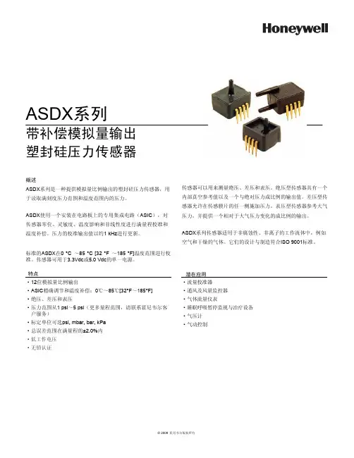
·低工作电压·无铅认证ASDX ㋏߫ᏺ㸹ٓᢳ䞣䕧ߎลᇕ⸙य़Ӵᛳ఼ὖ䗄ASDX ㋏߫ᰃϔ⾡ᦤկᢳ䞣↨՟䕧ߎⱘลᇕ⸙य़Ӵᛳ఼ˈ⫼Ѣ䇏প⒵ࠏᑺय़㣗ೈ⏽ᑺ㣗ೈݙⱘय़DŽASDX Փ⫼ϔϾᅝ㺙⬉䏃ᵓϞⱘϧ⫼䲚៤⬉䏃˄ASIC ˅ˈᇍӴᛳ఼䳊ԡǃ♉ᬣᑺǃ⏽ᑺᕅડ䴲㒓ᗻᑺ䖯㸠⒵䞣᷵ޚ⏽ᑺ㸹ٓDŽय़ⱘ᷵ޚ䕧ߎؐҹ㑺1 kHz 䖯㸠ᮄDŽᷛޚⱘASDX 0 °C ̚85 °C [32 °F ̚185 °F]⏽ᑺ㣗ೈ䖯㸠᷵ޚDŽӴᛳ఼ৃ⫼Ѣ3.3Vdc 5.0 Vdc ⱘऩϔ⬉⑤DŽӴᛳ఼ৃҹ⫼ᴹ⌟䞣㒱य़ǃᏂय़㸼य़DŽ㒱य़ൟӴᛳ఼᳝ϔϾݙ䚼ⳳぎখ㗗ؐҹঞϔϾϢ㒱ᇍय़៤↨՟ⱘ䕧ߎؐDŽᏂय़ൟӴᛳ఼ܕ䆌Ӵᛳ㝰⠛ⱘӏϔջᮑࡴय़DŽ㸼य़ൟӴᛳ఼খ㗗⇨य़ˈᑊᦤկϔϾⳌᇍѢ⇨य़ব࣪ⱘ៤↨՟ⱘ䕧ߎDŽASDX ㋏߫Ӵᛳ఼䗖⫼Ѣ䴲㜤㱔ᗻǃ䴲⾏ᄤⱘᎹ⌕ԧЁˈ՟བぎ⇨ᑆ➹ⱘ⇨ԧDŽᅗӀⱘ䆒䅵Ϣࠊ䗴ヺড়ISO 9001ᷛޚDŽ⡍⚍g 12ԡᢳ䞣↨՟䕧ߎg ASIC ㊒⹂䇗㡖⏽ᑺ㸹ٓ˖0ć̚85ć[32°F ̚185°F] g 㒱य़ǃᏂय़㸼य़g य़㣗ೈҢ1 psi ̚5 psi ˄䞣㣗ೈˈ䇋㘨㋏䳡ሐ䶺ᇨᅶ᠋᳡ࡵ˅g ᷛᅮऩԡৃ䗝psi, mbar, bar, kPa g ᘏ䇃Ꮒ㣗ೈ⒵䞣ⱘ±2.0%ݙ┰ᑨ⫼g ⌕䞣᷵ޚ఼g 䗮亢ঞ亢䞣ⲥ఼g ⇨ԧ⌕䞣Ҿ㸼g ⴵ᱖ذⲥ㾚Ϣ⊏⭫䆒g ⇨य़䅵g ⇨ࡼࠊ© 2009 䳡ሐ䶺ᇨ⠜ᴗ᠔᳝© 2009 霍尼韦尔版权所有2 霍尼韦尔传感与控制部ASDX 系列塑封硅压力传感器表1. 绝压最大额定值1参数最小最大单位供电电压(V 电源)-0.3 6.0V 任意引脚上的电压-0.3V 电源+0.3V ESD 感应(人体模式)3-kV 储存温度-50[-58]125[257]℃ [O F]焊接温度(2s 至4s)-250[482]℃ [O F]V 供电和接地之间的外部电容2100470nF表2. 操作规格参数最小典型最大单位供电电压(V 电源)33.3V 5.0V根据按订货指南选定的型传感器可以是3.3V ,也可以是5.0V(见图1) 3.04.753.345.043.65.25Vdc 供电电流 2.5mA补偿温度范围50[32]-85[185]℃ [O F]工作温度范围6-20[-4]-105[221]℃ [O F]过压72倍工作压力范围以上爆裂压力83倍工作压力范围以上启动时间(电源供应直至数据就绪)--5ms 响应时间-1.0-ms 最高输出限制97.5--%V 电源最低输出限制-- 2.5%V 电源最小负载电阻 5.0--k Ω总误差带9-- 2.0%FSS(满量程)10输出分辨率12--bits表3. 环境规格参数特性湿度0%至95%RH(相对湿度),无凝露振动20Hz 至2000Hz, 10G 冲击100G 持续11ms 寿命最少1百万次压力循环表4. 湿材料11参数端口1(压力端口)端口2(压力端口)密封盖玻璃充填PBT 玻璃充填PBT 粘合剂硅树脂RTV 硅树脂RTV 和环氧电气部件硅树脂和玻璃硅树脂、玻璃和金制品注:1. 绝对最大额定值是装置可以承受而不引起装置损坏的极限。
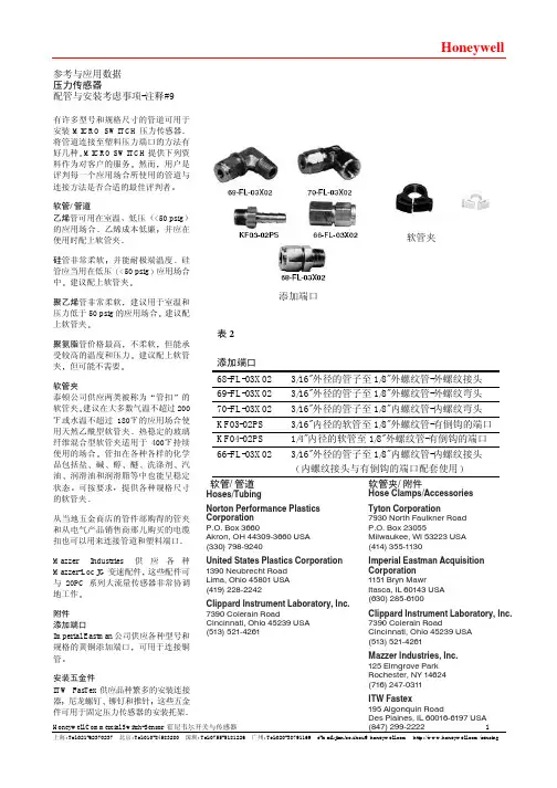
HoneywellHoneywell/Commercial Switch-Sensor 霍尼韦尔开关与传感器1 上海:Tel************* 北京:Tel************* 深圳:Tel************* 广州: Tel:020-********e-mail:******************************:///sensing参考与应用数据 压力传感器配管与安装考虑事项-注释#9有许多型号和规格尺寸的管道可用于安装MICRO SWITCH 压力传感器将管道连接至塑料压力端口的方法有好几种MICRO SWITCH 提供下列资料作为对客户的服务然而用户是评判每一个应用场合所使用的管道与连接方法是否合适的最佳评判者软管/管道乙烯管可用在室温低压<50 psig 的应用场合乙烯成本低廉并应在使用时配上软管夹硅管非常柔软并能耐极端温度硅管应当用在低压<50 psig 应用场合中建议配上软管夹聚乙烯管非常柔软建议用于室温和压力低于50 psig 的应用场合建议配上软管夹聚氨脂管价格最高不柔软但能承受较高的温度和压力建议配上软管夹但可能不需要软管夹泰顿公司供应两类被称为管扣的软管夹建议在大多数气温不超过200℉或水温不超过180℉的应用场合使用天然乙酰型软管夹热稳定的玻璃纤维混合型软管夹适用于400℉持续使用的场合管扣在各种各样的化学品包括盐碱醇醚洗涤剂汽油润滑油和润滑脂等中也能呈稳定状态可按要求提供各种规格尺寸的软管夹从当地五金商店的管件部购得的管夹和从电气产品销售商那儿购买的电缆扣也可以用来连接管道和塑料端口Mazzer Industries 供应各种Mazzer-Loc JG 变速配件这些配件可与20PC 系列大流量传感器非常协调地工作 附件 添加端口Imperial Eastman 公司供应各种型号和规格的黄铜添加端口可用于连接铜管安装五金件ITW FasTex 供应品种繁多的安装连接器尼龙螺钉铆钉和推针这些五金件可用于固定压力传感器的安装托架添加端口软管/管道软管夹3/16"外径的管子至1/8"外螺纹管-外螺纹接头表2添加端口68-FL-03X02 69-FL-03X02 3/16"外径的管子至1/8"外螺纹管-外螺纹弯头 70-FL-03X02 3/16"外径的管子至1/8"内螺纹管-内螺纹弯头 KF03-02PS 3/16"内径的软管至1/8"外螺纹管-有倒钩的端口 KF04-02PS 1/4"内径的软管至1/8"外螺纹管-有倒钩的端口 66-FL-03X02 3/16"外径的管子至1/8"内螺纹管-内螺纹接头内螺纹接头与有倒钩的端口配套使用软管夹/附件 Hoses/TubingNorton Performance PlasticsCorporationP.O. Box 3660Akron, OH 44309-3660 USA (330) 798-9240United States Plastics Corporation 1390 Neubrecht Road Lima, Ohio 45801USA (419) 228-2242Clippard Instrument Laboratory, Inc.7390 Colerain Road Cincinnati, Ohio 45239 USA (513) 521-4261Hose Clamps/Accessories Tyton Corporation 7930 North Faulkner Road P.O. Box 23055Milwaukee, WI 53223 USA (414) 355-1130Imperial Eastman Acquisition Corporation1151Bryn MawrItasca, IL 60143 USA (630) 285-6100Clippard Instrument Laboratory, Inc.7390 Colerain RoadCincinnati, Ohio 45239 USA (513) 521-4261Mazzer Industries, Inc.125 Elmgrove Park Rochester, NY 14624(716) 247-0311ITW Fastex195 Algonquin RoadDes Plaines, IL 60016-6197 USA(847) 299-2222。

Datasheet2What makes our sensors better:• Robust IC design with ESD Class 2, reversepolarity protection and 150 °C [302 °F] capability • Package and sensitivity options to bettermatch application needs • Dependable performance – similar Honeywellsensor ICs have been tested to over 100 million operations • Honeywell legacy and expertise – 45 yearsof engineering excellence and Hall effect technology experienceUnipolar Digital Hall-Effect Sensor ICsThe SS340RT/SS440R sensor ICs are small, versatile digital Hall-effect devices that are operated by the magnetic field from a permanent magnet or an electromagnet. They are designed to respond to a single pole: North (SS340RT) or South (SS440R).These unipolar Hall ICs are supplied in three different magnetic sensitivities to meet a wide range of potential applications:• SS341RT and SS441R offer the highest sensitivity, with a typical operating point of 75 G at 25 °C [77 °F]. • SS343RT and SS443R offer medium sensitivity, with a typical operating point of 135 G at 25 °C [77 °F]. • SS349RT and SS449R offer the lowest sensitivity, with a typical operating point of 305 G at 25 °C [77 °F].These sensors are available in two package styles:• The SS340RT is available in the miniature SOT-23 surface mount package. • SS440R is available in the leaded, flat TO-92-style package.The SS340RT’s small size requires less PC board space, allowing it to be used in smaller assemblies. Its 3 Vdc capability allows for use in low voltage applications, promoting energy efficiency.The SS340RT Series is available on tape and reel (3000 units per reel); the SS440R Series is available in a bulk package (1000 units per bag).SMALL • VERSATILESS340RTSS440R3 SubminiaTuRe package Size (SS340RT) Supplied on Tape and ReelAllows for a compact design with automated component placement, helping to reduce manufacturing costsSimple acTivaTion fRom a Single pole and mulTiple magneTic SenSiTiviTieS (high, medium and low)Make this product suitable in a variety of potential motion control, lid closure detection, and displacement sensing applicationslow volTage 3 v capabiliTyHelps reduce power consumptionbuilT -in ReveRSe polaRiTy pRoTecTionProtects the device from potential damage during installationTheRmally balanced inTegRaTed ciRcuiTProvides for stable operation over a wide temperature range of -40 °C to 150 °C [-40 °F to 302 °F]RohS-complianT maTeRialSMeet Directive 2002/95/ECFeatures and BenefitsHigh, medium and low magnetic sensitivities.Enhances application flexibility.4induSTRialdooR oR lid cloSuRe deTecTion in applianceS oR elecTRonically conTRolled conTaineRSMay be used recessed in the door frame with a magnet embedded in the door. The magnet activates the sensor to indicate door open or close.Simple Speed and Rpm (RevoluTionS peR minuTe) SenSing in fiTneSS and induSTRial equipmenTMay be mounted on the motor shaft of a treadmill such that the rotating magnet pole, which rotates with the motor, activates the sensor with each revolution, producing a single digital pulse for each revolution.flow RaTe SenSing in waTeR SofTeneRS, induSTRial pRoceSSeS, and applianceSMay be used used with one or more magnets mounted on a paddle to measure the flow rate.dampeR oR valve poSiTion conTRol in induSTRial, hvac and ReSidenTial oR commeRcial applicaTionSMay be used to determine if a valve or damper is fully open or fully closed.RoboTic conTRol (cylindeR poSiTion moniToRing)May be used to detect the piston’s position by detecting a magnet mounted on the piston ring located inside a non-ferromagnetic cylinder.level/TilT meaSuRemenTMay be installed in the base of a machine with a magnet mounted pendulum fashion over the sensor. A change in state of the output as the magnet swings away from the sensor indicates that the machine is not level.RemoTe conveyoR SenSingMay be mounted to the frame of the conveyor, with a magnet mounted on the tail pulley. When the magnet revolves past the sensor, it produces one output per revolution, providing an intermittent visual or audible signal at a remote location to assure stability. Any interruption of the conveyor motion will interfere with the normal signal and alert the operators.puSh buTTon conTRolS medicalpoSiTion SenSoR in hoSpiTal bedS and medical equipmenTMay be used with a magnet mounted on the activator arm to determine the home or end-of-travel position of the equipment.medicaTion bin moniToR on poRTable dRug caRTSMay be used to detect if a drug dispensing drawer is open or closed.Potential Applications5Unipolar Digital Hall-Effect Sensor ICsTable 2. SS340RT/SS440R magnetic Specifications (v = 3 vdc to 24 vdc, 20 ma load, T = -40 ºc to 150 ºc [-40 ºf to 302 ºf].)Table 1. SS340RT/SS440R performance Specifications (v supply = 3 vdc to 24 vdc, 20 ma load, T a = -40 ºc to 150 ºc [-40 ºf to 302 ºf] except where otherwise specified.)Table 3. SS340RT/SS440R absolute maximum Ratings NOTICEAbsolute maximum ratings are the extreme limits that the device will withstand without damage to the device. However, the electrical and mechanical characteristics are not guaranteed as the maximum limits (above recommended operating conditions) are approached, nor will the device necessarily operate at absolute maximum ratings.NOTICEThe magnetic field strength (Gauss) required to cause the switch to change state (operate and release) will be as specified in the magnetic characteristics. To test the switch against the specified magnetic characteristics,the switch must be placed in a uniform magnetic field.SS340RT/SS440R Seriesfigure 1. Typical magnetic vs Temperature performance curves SS341RT/SS441RSS343RT/SS443R SS349RT/SS449ROperate PointVcc = 12 VRelease Point20406080100-40-20020406080100120140 MagneticSwitchPoint(Gauss)Temperature (C)Magnetic Performance vs TemperatureOperate PointVcc = 12 VRelease Point50100150200250300350-40-20020406080100120140 MagneticSwitchPoint(Gauss)Temperature (C)Magnetic Performance vs Temperature20406080100-40-20020406080100120140 MagneticSwitchPoint(Gauss)Temperature (C)120140160180Unipolar Digital Hall-Effect Sensor ICsfigure 2. SS340RT Series maximum Rated Supply voltage vs Temperaturefigure 3. current Sinking output block diagramfigure 4. wiring diagrams7SS340RT/SS440R Seriesfigure 5. SS340RT mounting and Tape/Reel dimensions (for reference only. mm/[in].)MEASUREDA T HUB9Unipolar Digital Hall-Effect Sensor ICsorder guide figure 6. SS440R mounting dimensions (for reference only. mm/[in].)Sensing and Control Honeywell1985 Douglas Drive North Golden Valley, MN 55422 Find out moreHoneywell serves its customers through a worldwide network of sales offices, representatives and distributors. For application assistance, current specifications, pricing or name of the nearest Authorized Distributor, contact your local sales office.To learn more about Honeywell’s sensing and control products, call +1-815-235-6847 or 1-800-537-6945,visit , or e-mail inquiries to *********************addiTional infoRmaTionThe following associated literature is available at : • Product line guide• Product range guide: Position Sensors • Product range guide: Speed Sensors• Product range guide: Sensors and Switches for Potential Medical Applications• Product installation instructionswaRRanTy/RemedyHoneywell warrants goods of its manufacture as being free of defective materials and faulty workmanship. Honeywell’s standard product warranty applies unless agreed to otherwise by Honeywell in writing; please refer to your order acknowledgement or consult your local sales office for specific warranty details. If warranted goods are returned to Honeywell during the period of coverage, Honeywell will repair or replace, at its option, without charge those items it finds defective. The foregoing is buyer’s sole remedy and is in lieu of all other warranties, expressed or implied, including those of merchantability and fitness for a particular purpose. in no event shall honeywell be liable for consequential, special, or indirect damages.While we provide application assistance personally, through our literature and the Honeywell website, it is up to the customer to determine the suitability of the product in the application.Specifications may change without notice. The information we supply is believed to be accurate and reliable as of this printing. However, we assume no responsibility for its use.005909-4-EN IL50October 2014© 2014 Honeywell International Inc. All rights reserved.Mouser ElectronicsAuthorized DistributorClick to View Pricing, Inventory, Delivery & Lifecycle Information:H oneywell:SS441R SS449R SS443R SS343RT SS341RT SS349RT。

(casing and cementing) are vital oil and gas processes that utilize pressure sensors for measurement and monitoring functions.APPLICATIONSHoneywell Wing Union pressure sensors (also known as Hammer Union pressure sensors outside of the United States) are widely used by oil and gas companies to measure pressure level changes in media circulation systems.Oil Mud LoggingFor example, oil mud loggingapplications (see Figure 1) require a series of pressure sensors to be connected to the drilling apparatus and installed in specialized equipment to monitor or “log” the drill’s activity. Logging While Drilling (LWD) and Measurement While Drilling (MWD)pump into the well), mud pumps (for pressure monitoring of incoming and outgoing media to protect the mudpump and drill bit), and return line choke manifold (for pressure monitoring of the return line carrying the mud plus cuttings).During the mud logging process, pumps send drilling media throughout the circulation system, down to the drilling bit, and then return the bit’s cuttings to the surface for analysis and disposal. Honeywell’s wing union/hammer union pressure sensors help detect pressure level changes in the media circulation system, which can indicate changing conditions being encountered downhole by the drill bit, thus allowing the operator to quickly make adjustments to the drilling mixture pressure or drilling process as needed.today’s oil and gas industry, used for many types Models 434, 435, 437 Wing Union/ Hammer Union Pressure TransducerPRESSURE SENSORS FOROIL & GASApplication NoteFracturing, Acidizing, and Cementing Honeywell’s Wing Union/Hammer Union pressure sensors are also used during fracturing, acidizing, and cementing applications for similar pressure monitoring and control purposes.SOLUTIONSHoneywell Wing Union/Hammer Union Pressure Sensors are built ruggedand oilfield tough to stand up to the rigorous demands of oil and gas drilling applications and environments. They have the sensitivity to ensure precise, reliable measurements every time, optimize drilling operation, reduce downtime, and maximize productivity. Durable ConstructionModels 434, 435, and 437 are constructed on Honeywell’s time proven all-welded, one-piece design, with the sensor diaphragm and Weco® 1502, 2202 Wing Union compatible fitting form factor machined as one part. This one-piece design provides a hermetically sealed unit, reducing the chanceof media leakage into the sensitive electronic components, and increasing overall reliability. The isolated, pressure sensing diaphragm minimizes zero-shift during hammer up and also eliminates long term, signal drift in the field, making it easier to install and providing reliable pressure readings over time.The sensor diaphragm is machined from Inconel® 718, which provides additional durability with highly abrasive and corrosive media, and is weldedto the main stainless steel body. The stainless steel electrical connection provides enhanced secondary pressure containment, with multiple electricalconnector options from which to choose.Optional 1-Wire or 2-Wire ShuntCalibrationModels 434, 435, and 437 providean optional 1-wire or 2-wire shuntcalibration. When a customer sends asignal to the wing union/hammer unionfrom their instrumentation, anothersignal will be returned to validate thefunctionality of the unit. This providesconfidence in the pressure readingsduring normal operation.Optional Protective CageModels 434, 435, and 437 are alsoavailable with an optional protectivecage which provides extra electricalconnection protection and durability.Various Accuracy Levels• Model 434: 0.2 %FSS BFSL• Model 435: High accuracy±0.1 %FSS BFSL orstandard accuracy ±0.2 %FSS BFSL• Model 437: Standard accuracy±0.2 %FSS BFSLModel 437 feature a wider aperturedesign than the other models that isuseful for customers utilizing moreviscous media in certain applications,enabling uniform flow of differentviscous media through the criticalsensing area and helping to maintainconsistent accuracy.*Best Fit Straight LineBENEFITS• Higher ±0.1 %FSS BFSL Accuracy(Model 435): Provides additionalconfidence in the actual measuredpressure value, particularly forsmaller changes in pressure, thusallowing the operator to makequicker adjustments to drillingoperations for more precise controland increased efficiency duringextraction• Wider Aperture Design (Model 437):Wider than Models 434 and 435,helping to prevent media cloggingwhen using more viscous mediablends• Reliability/Durability: All-welded,hermetically sealed, stainless steelconstruction with Inconel® 718wetted parts isolate corrosive orabrasive drilling media from sensitiveinternal electronics; materials retainstrength in higher temperatures toprovide reliable performance underdemanding conditions; shock andvibration tested, intrinsically saferating• Easy Installation/Serviceability:Designed for quick field installation,including horizontal or verticalmounting; field-repairableconnectors; zero and spanadjustments can be accessed byremoving the electrical connector,thus preventing ingress failures anddeterring tampering; 1-wire or 2-wireshunt calibration allow the user todetermine if the wing union/hammerunion is still functional in the field,or if it has to be removed for service/calibration.2 APPLICATION NOTE | Wing Union/Hammer Union Pressure Transducers | /astAPPLICATION NOTE | Wing Union/Hammer Union Pressure Transducers | /ast 3SELECTION GUIDEHoneywell offers three models from which to choose:üüü üüü üüü* Note: See Wing Union pressure sensor datasheet for more agency approval classifications.For more information about Wing Union/Hammer Union pressure sensors, including nomenclature and dimensional drawings, see our datasheet.008875-6-EN | 6 | 10/21© 2021 Honeywell International Inc. All rights reserved.HoneywellAdvanced Sensing Technologies 830 East Arapaho Road Richardson, TX 75081WARRANTY/REMEDYHoneywell warrants goods of its manufacture as being free of defective materials and faulty workmanship during the applicablewarranty period. Honeywell’s standard product warranty applies unless agreed to otherwise by Honeywell in writing; please refer to your order acknowledgement or consult your local sales office for specific warranty details. If warranted goods are returned to Honeywell during the period of coverage, Honeywell will repair or replace, at its option, without charge those items that Honeywell, in its sole discretion, finds defective. The foregoing is buyer’s sole remedy and is in lieu of all other warranties, expressed or implied, including those of merchantability and fitness for a particular purpose. In no event shall Honeywell be liable for consequential, special, or indirect damages.While Honeywell may provide application assistance personally, through our literature and the Honeywell web site, it is buyer’s sole responsibility to determine the suitability of the product in the application.Specifications may change without notice. The information we supply is believed to be accurate and reliable as of this writing.However, Honeywell assumes no responsibilityfor its use.FOR MORE INFORMATIONHoneywell Advanced Sensing Technolo-gies services its customers through a worldwide network of sales offices and distributors. For application assistance, current specifications, pricing, or the nearest Authorized Distributor, visit /ast or call:USA/Canada +302 327 8920Latin America +1 305 805 8188Europe +1 302 327 8920Japan +81 (0) 3-6730-7152Singapore +65 6355 2828Greater China+86 4006396841。
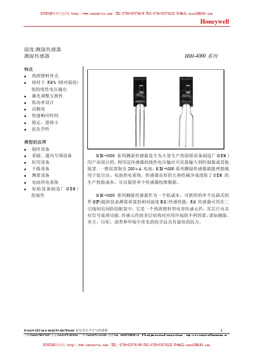
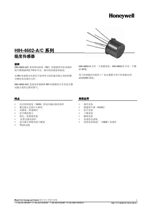
湿度/测湿传感器测湿传感器HIH-4000系列特点热固塑料外壳相对于RH%(相对湿度)值的线性电压输出激光调整互换性低功率设计高精度快速响应时间稳定,漂移小抗化学性典型的应用制冷设备采暖、通风空调设备医用设备干燥设备测量设备电池供电系统原始设备制造厂(OEM)组装件HIH-4000系列测湿传感器是专为大量生产的原始设备制造厂(OEM)用户而设计的。
利用这传感器的线性电压输出可直接输入到控制器或其他装置。
一般仅需取出200μA电流,HIH-4000系列测湿传感器就能理想地用于低引出、电池供电系统。
传感器良好的互换性减少或消除了OEM的生产校验成本。
可以提供单个传感器校准数据。
HIH-4000系列测湿传感器作为一个低成本、可软焊的单个直插式组件(SIP)提供仪表测量质量的相对湿度(RH)传感性能。
RH传感器可用在二引线间有间距的配量中,它是一个热固塑料型电容传感元件,其芯片内具有信号处理功能。
传感元件的多层结构对应用环境的不利因素,诸如潮湿、灰尘、污垢、油类和环境中常见的化学品具有最佳的抗力。
表1:性能规格在5.0 VDC供电电压和25°C时,除非另有规定%RH性能规格包括试验系统测量误差(±0.5%的典型值)参数最小值典型值最大值单位互换性(最佳配合直线)%RH0至60%RH-5 5%RH60%至100%-8 8互换性(二阶曲线)%RH±3.5%RH*精度(最佳配合直线)±3.5%RH**精度电压输出(二阶曲线)±2.5%RH 滞后性 3%RH重复精度±0.5整定时间70mSSec响应时间l/e指在缓慢流动的空气中15***稳定性(在1年内50%RH 的条件下)%RH±1.2****稳定性(50%RH条件下 ) %RH供电要求TBDVDC5.8供电电压 4μA供电电流500电压输出(一阶配合) V输出=V供电(0.0062(传感器RH)+0.16)电压输出(二阶曲线配合) V输出= 0.00003 (传感器RH)2 + 0.0281 (传感器RH) +0.820,在25°C时的典型数据温度补偿V输出=(0.0305+0.000044T-0.0000011T2) (传感器RH)+ (0.9237-0.0041T+0.000040T2)T=温度单位为°C工作温度-40 见图1 85 °C°F-40 185工作湿度 0见图1 100 %RH储存温度°C-40 125°F-40 257储存湿度见图2 %RH* 仅对HIH-400-003和-004型号而言。
电子罗盘模块按照NMEA格式,通过RS232/485串口提供航向输出(横滚、俯仰、偏航)采用Honeywell公司的固态磁阻传感器,具有快速的响应时间至20Hz,航向精度为0.5˚ ,分辨率为0.1˚。
快速响应时间小体积低功耗高精度宽的倾斜角度对铁磁物性金属进行补偿使用固态磁传感器提高了响应速度,和万向架固定式的磁通门传感器相比提高了数据更新速度。
仅为一块线路板,重量小于57克,体积为83x25x22mm,铝外壳封装。
功耗小于25mA,可长时间电池供电0.5˚ 航向精度,分辨率0.1˚ ,可适用于严格定向的应用场合。
倾斜角度为±40˚ ,适合于广泛的要求精确的应用通过对因环境中存在铁磁性金属而对地磁场造成的扭曲的补偿,提高精度。
下表显示,9针插头引脚排列,电源可以为调制的5V ,或不调制6—15V ,只有#9针或#8针中的一个,可由给定连接方法连接。
见以下:接口信号描述通信HMR3000 用简单的ASCII 字符与外部主控制器,通过 RS-232 或 RS-485 通讯。
ASCll 码的发送和接收,使用1个起始位,8个数据位(先是LSB,MSB 总为0) ,无奇偶位,和一个停止位,波特率可设置为1200,2400,4800,9600,19200或38400,HMR3000 对所有收到的带校验码的有效输入作反应。
罗盘输出HMR3000输出三种NMEA 标准格式(HDG,HDT 和XDR),三种专用格式(HPR,RCD 和CCD),及一个 ASCll 码航向输出,用于数据显示。
HDG,HDT 和HPR 是最通用格式。
$HCHDG 航向、偏差角、磁偏角$HCHDG, 85.5, 0.0, E, 0.0, E*77$HCHDT,航向、对(True)$HCHDT,271.1,T*2C$PTNTHPR,航向、俯仰和横滚$PTNTHPR,Heading,Heading Status,Pitch,Pitch Status,Roll,Roll Status*hh<cr><lf>$PTNTHPR,85.9,N,-0.9,N,0.8,N*2C名称TxD/B RxD/A GND 6-15V 5VOper/Calib(2)Run/Stop(2)Ready/Sleep(2)Cont/Reset(2)入/出Out In In In In In In In In引脚235981647描述RS-232 发送/ RS-485RS-232 接收 / RS-485电源/信号地未调理的电源电压输入调理的电源电压输入Operate/Calibrate (3) input (open=Operate)Run/Stop (3) input (open=Run)Ready/Sleep (3) input(open=Ready)Continue/Reset (3) input (open=Continue)(典型值)---6-155 ± 5%0-50-50-50-5(最小值)(1)-18-1800-20-20-20-20单位Vdc VdcVdc Vdc Vdc Vdc Vdc Vdc(最大值)(1)1818307.520202014(1) 绝对最大值(2) 沉电流:200µA (典型值), 400mA(最大值)(3) 开路输入 =高电平HMR3000 连线图——计算机RS232 到 HMR3000订货指南HMR3000-Demo-232*.....RS232HMR3000-D00-232..........RS232.........NoneHMR3000-D21-232..........RS232.........Extended BaseHMR3000-D00-485..........RS485.........NoneHMR3000-D21-485..........RS485.........Extended Base*Development Kit includes one module in alu minum enclosure, cablingwith power supply, demonstration software for PC running Windows™and User’s Manual.数值<0.5˚<1.5˚± 0.3˚0.1˚degrees/mils ±40˚±0.4˚±0.6˚±0.2˚0.1˚degree/mils ±1.0 Gauss (最大值)1 mGauss 5.0 Vdc 调理电压6~15Vdc 未调理电压35 mA@6 Vdc13 mA 2.0 mA RS-232RS-4851200 to 38400 bps NMEA 0183连续滤波0.75 oz (22g)3.25 oz (92g)1.2 x 2.95 x 0.7601.5 x 4.2 x 0.88-20 to 70˚C -35 to 100˚C 30 英寸高落下20~2000Hz Random 2 hrs/axisIPC6012IPC610航向角俯仰和横滚磁场电气接口物理环境制造指标1. 航向精度是假设地球磁体只有硬铁干扰,已通过标定进行补偿2. 标定值3. 由设计参数保证4. 典型5. 迟到或超过*器件方向角不超过75˚在工作或贮存时——可引起短暂的精度损失。
目录:水系统传感器 (2)水流开关WFS-1001-H (2)液位开关MAC-3-5M (2)水管式压差传感器P7620C (3)水管式压力传感器P7620A (4)流量变送器8550+2517 (5)VF20T浸入式温度传感器 (5)风系统传感器 (7)DPS系列气流压差开关 (7)DPTM系列压差变送器 (7)风管式温度传感器LF20 (8)风管式温度传感器LF20-C (9)室外温度传感器T7416A1022 (9)室内温度传感器T7412A1000 (9)室内温度传感器CTR21 (10)风管式温湿度传感器H7050B1018 (10)风管式温湿度变送器H7050B1117 (11)室内温湿度变送器H7030A1000 (12)室内温湿度传感变送器H7012B1023 (12)室内温湿度传感器CTR21-H (13)风管式温湿度传感器H7015B1020 (14)室外温湿度传感变送器H7508A1042 (14)CDS2000 系列二氧化碳传感器 (15)C7110C1001(替换已停产的AQS51) 系列二氧化碳传感器 (15)AQS71-KAM(替换已停产的AQS51-KAM) 系列二氧化碳传感器 (16)GD250W3E 系列一氧化碳传感器 (17)C7110A1005系列房间空气质量传感器 (17)L4064K1006B 高温断路开关,手动复位 (18)T6950A1000 低温短路开关,手动复位 (18)数字化挂墙模块T7560 温度传感器 (19)数字化挂墙模块T7460 温度传感器 (19)水系统传感器水流开关 WFS-1001-H应用∙ WFS 水流开关具有SPDT 输出,性能优异,高精度可靠性,可安装在水管和对铜无腐蚀性液体中,当液体流量达到整定速率时,可不到整定点,其一个回路关闭,另一个回路打开,典型应用于连锁作用或断流保护的场所。
∙ WFS 系列开关仅用0℃以上液体介质,它亦可于高盐或氯气的液体,但是非易燃介质。
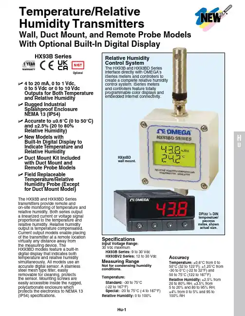
Hu-1HuSpecificationsInput Voltage Range: 30 Vdc maximumHX93B Series: 9 to 30 Vdc HX93BV2 Series: 12 to 30 VdcMeasuring RangeNot for condensing humidity conditions.Temperature:Standard: -30 to 75°C (-22 to 167°F)Special: -20 to 75°C (-4 to 167°F)Relative Humidity: 0 to 100%AccuracyTemperature: ±0.6°C from 0 to 50°C (32 to 122°F); ±1.25°C from -30 to 0°C (-22 to 32°F) and 50 to 75°C (122 to 167°F)Relative Humidity: ±2.5% from 20 to 80% RH; ±3.5% from 5 to 20% and 80 to 95% RH; ±4% from 0 to 5% and 95 to 100% RHThe HX93B and HX93BD Series transmitters provide remote andon-site monitoring of temperature and relative humidity. Both series output a linearized current or voltage signal proportional to the temperature and relative humidity. Relative humidity output is temperature compensated. Current output models enable placing of the transmitter at a remote location virtually any distance away from the measuring device. TheHX93BD models feature a built-in digital display that indicates both temperature and relative humidity simultaneously. All models use an accurate digital sensor. A stainless steel mesh type filter, easily removable for cleaning, protects the sensor. Mounting screws are easily accessible inside the rugged, polycarbonate enclosure whichprotects the electronics to NEMA 13 (IP54) specifications.DPi32 1⁄32 DIN temperature/process U 4 to 20 mA, 0 to 1 Vdc, 0 to 5 Vdc or 0 to 10 VdcOutputs for Both Temperature and Relative Humidity U R ugged IndustrialSplashproof Enclosure NEMA 13 (IP54)UA ccurate to ±0.6°C (0 to 50°C) and ±2.5% (20 to 80% Relative Humidity)U N ew Models withBuilt-In Digital Display to Indicate Temperature and Relative Humidity U D uct Mount Kit Included with Duct Mount and Remote Probe Models U F ield Replaceable Temperature/Relative Humidity Probe (Except for Duct Mount Model)Relative Humidity Control SystemThe HX93B and HX93BD Series interface directly with OMEgA’s iSeries meters and controllers to create a complete relative humidity control system. iSeries meters and controllers feature totally programmable color displays and embedded internet connectivity.Temperature/Relative Humidity TransmittersWall, Duct Mount, and Remote Probe Models With Optional Built-In Digital DisplayOptionalHu-2OutputHX93BC or HX93BDC:4 to 20 mA for 0 to 100% RH and -30 to 75°C (-22 to 167°F)HX93BV0: 0 to 1 Vdc for 0 to 100% RH and -30 to 75°C (-22 to 167°F)HX93BV1: 0 to 5 Vdc for 0 to 100% RH and -30 to 75°C (-22 to 167°F)HX93BV2: 0 to 10 Vdc for 0 to 100% RH and -30 to 75°C (-22 to 167°F)Relative Humidity Temperature Compensation: -30 to 75°C (-22 to 167°F)Temperature Response Time: 5 seconds minimum, 30 seconds maximumRelative Humidity Response Time: 8 second typicalRepeatability: ±0.1% RH, ±0.2°C (0.4°F)Sample Rate: 1 sample every 4 seconds Housing: gray polycarbonate, NEMA rated up to 13 (IP54)Connections: Liquid-tight nylon with neoprene gland, for 2.50 to 8.00 mm (0.09 to 0.315") diameter cable; internal 6 position terminal block accepts 14 to 22 gauge wire Dimensions:HX93B(*) (without Probe):80.01 L x 82.30 W x 55.63 D mm (3.15 x 3.24 x 2.19")HX93B(*)-D (with Probe):80.01 L x 82.30 W x 183.13 D mm (3.15 x 3.24 x 7.21")TP-SP (Short Probe):ø16 x 71.88 L mm (ø0.63 x 2.83")Weight:HX93B(*): 251 g (8.9 oz) HX93B(*)-D: 256 g (9.0 oz) HX93B(*)-RP1: 352 g (12.4 oz)Display (HX93BD Series Only)Indicators: Two 4 digit backlit LCD Display Rate: 1 reading per second Display Resolution:Relative Humidity: 0.1% RH Temperature: 0.1°C (0.1°F)*For 4 to 20 mA output specify “C”, for 0 to 1 Vdc output specify “V0”, for 0 to 5 Vdc output specify “V1”, and for 0 to 10 Vdc output specify “V2”.TH-SPshort probe with M12 HX93B(*)-D duct mount transmitter.HX93BD(*)-D duct mounttransmitter with display.All models shown smaller than actual size.HX93B(*)TH-RP remote probe with 3 m (10') cable and M12 connector.C o n n (not available with duct mount models).。
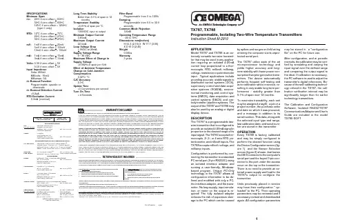
may be stored in a "configuration file" on the PC for future use.After configuration, and at periodic intervals, the calibration may be veri-fied by simulating and varying the input signal over the defined range and comparing the output signal to the ideal. If calibration is necessary,the PC software is used to adjust the transmitter's digital references. Be-cause of the self-calibrating technol-ogy utilized in the TX787, the cali-bration verification interval may be significantly longer than for earlier technology transmitters.The Calibration and Configuration Software, Isolated RS232/TX787Communications Adapter and User's Guide are included in the model TX780-SOFT.by spikes and surges on field wiring entering the computer via its unpro-tected serial port.The TX787 utilize state of the art microprocessor technology and yields higher accuracy and long-term stability with lower power con-sumption than prior generation trans-mitters. The device automatically performs frequent self-testing and auto-calibration while in service, re-sulting in very stable long-term per-formance - stability greater than 0.1% of span over 12 months.To maximize traceability, each unit may be assigned a tagID, a job or a project number, the purchase order and date on which it was procured,and a message in addition to its serial number. This data, along with the selected input type and range,last calibration date, and serial num-ber are stored in the transmitter.OPERATIONEvery TX788 is factory calibrated and may be simply configured to perform the desired function using the Device Configuration screen (fig-ure 1) and the Sensor Selection screen (figure 2) shown. Just fasten the DB-9 connector to the computer's serial port and the keyed 5-pin con-nector to the port under the access cover on the top or the transmitter.There is no need to provide an ex-ternal power supply and load to the TX787's output to configure the transmitter.Units previously placed in service may have their configuration " up-loaded" to the PC. Their operating parameters may be reviewed and if necessary revised and downloaded again. All configuration parametersAPPLICATIONModel TX787 and TX788 is an ex-tremely versatile two-wire transmit-ter that may be used in any applica-tion requiring an isolated 4-20mA current loop proportional to a ther-mocouple, RTD, millivolt, milliamp,voltage, resistance or potentiometer input. Typical applications include providing accurate, stable signals to distributed control systems (DCS),supervisory control and data acqui-sition systems (SCADA), environ-mental monitoring and control sys-tems (EMCS), data acquisition and control systems (DACS) and cus-tody transfer / pipeline systems. The output of the TX787 and TX788 may also be used by an analog or digital display device.DESCRIPTIONThe TX787 is a programmable two-wire transmitter that is configured to provide an isolated 4-20mA signal in proportion to the desired range of its input signal. The TX787 accepts ther-mocouple, 2-,3-, or 4 wire RTD, po-tentiometer, and millivolt inputs. The TX788 accepts millivolt, voltage, and milliamp inputs.Configuration is performed by con-necting the transmitter to a standard PC serial port (9-pin RS232C) using an isolated interface adapter and running a user-friendly, Windows-based program. Unique PC-Only technology in the TX787 allows all configuration information to be de-fined and modified with only a PC,the interface adapter, and the trans-mitter. No loop supply, input simula-tion, or meter on the output is re-quired! The fully isolated adapter reduces the risk of expensive dam-age to the PC which can be causedTX787, TX788Programmable, Isolating Two-Wire Temperature TransmittersInstruction Sheet M-2919SPECIFICATIONS Minimum Span t/c:200C if zero offset < 6500C500C if zero offset > 6500C 1250C if zero offset > 12500C (type C only)RTD:120C if zero offset < 750C200C if zero offset < 2750C 500C if zero offset > 2750CmV:1mV if zero offset < 25mV 5mV if zero offset < 150mV 10mV if zero offset > 150mV mA:1mA if zero offset < 15mA 3mA if zero offset > 15mAVolts:0.3V if zero offset < 5V0.5V if zero offset > 5VInput ImpedenceVolts: 200k ΩMillivolts: 10m ΩMilliamps: 5Ωt/c Burnout FunctionProgrammable: upscale or downscalet/c Burnout Detection Current<0.2µARTD Excitation CurrentFilter BandProgrammable from 0 to 120%DampingProgrammable from 0.0 to 32.0secondsCommon Mode Rejection120dBOperating Temperature Range-20 to 70o CDimensions mm(inches)H 55.3 (2.10) X W 77.7 (3.06)X D 61.0 (2.40)Weight0.56lbs Warranty3 yearsLong Term StabilityBetter than 0.1% of span in 12monthsTemperature Stability<0.01% of span per 0C Isolation1000VDC input to output Minimum Output Current3.85mAMaximum Output Current22.5mALoop Voltage Drop< 9VDC at 20mA Supply Voltage Range9 - 36 VDCMaximum Effect of Change in Supply Voltage<0.002% of span per Volt Effect of Ambient Temperature Change on Cold Junction Compensation0.020C/ 0C CJC Accuracy0.50C Update Time>3 Conversions per second Turn On Time< 4 SecondsFax: (95) 203-359-7807e-mail:*****************Fax: (514) 856-6886Fax: (203) 359-7700Servicing Europe:Fax: (31) 20 6434643Fax: 49 (07056) 8540Postbus 8034, 1180 LA Amstelveen, The Netherlands Tel: (31) 20 6418405Toll Free in Benelux: 06 0993344e-mail:************Ostravska 767, 733 01 Karvina Tel: 42 (69) 6311899e-mail:***************9, rue Denis Papin, 78190 Trappes Tel:33 0130-621-400Toll Free in France: 05-4-06342e-mail:****************Daimlerstrasse 26, D-75392 Deckenpfronn, GermanyTel:49 (07056) 3017Toll Free in Germany: 0130 11 21 66e-mail:*****************25 Swannington Road,Broughton Astely, Leicestershire,LE9 6TU, England Tel: 44 (1455) 285520Fax: 44 (1455) 283912Fax: 33 0130-699-120Fax: 42 (69) 6311114P.O. Box 7, Omega Drive Irlam, Manchester,M44 5EX, England Tel: 44 (161) 777-6611Fax: 44 (161) 777-6622Toll Free in England: 0800-488-488e-mail:************976 BergarLaval (Quebec) H7L 5A1Telephone: (514) 856-6928e-mail:****************For immediate technical sevice or application assistance:Sales Service: 1-800-826-6342 / 1-800-TC-OMEGA Customer Service: 1-800-622-2378 / 1-800-622-BEST Engineering Service: 1-800-872-9436 / 1-800-USA-WHEN TELEX: 996404 EASYLINK: 62968934 CABLE: OMEGA Tel: (95) 800-TC-OMEGA En Espanol: (203) 359-1660 ext. 2203Stamford, CT 06907-0047Telephone: (203) 359-1660e-mail:**************ISO 9001 CertifiedCanada:USA and Canada:Mexico and Latin America:Benelux:Czech Republic:France:Germany/Austria:United Kingdom:ISO 9002 CertifiedRETURN REQUEST/ INQUIRIESDirect all warranty and repair requests/inquiries to the OMEGA Customer Service Department. BEFORE RETURNING ANY PRODUCT(S) TO OMEGA,PURCHASER MUST OBTAIN AN AUTHORIZED RETURN (AR) NUMBER FROM OMEGA'S CUSTOMER SERVICE DEPARTMENT (IN ORDER TO AVOID PROCESSING DELAYS). The assigned AR number should then be marked on the outside of the return package and on any correspondence.The purchaser is responsible for shipping charges, freight, insurance and proper packaging to prevent breakage in transit.FOR WARRANTY RETURNS, please have the following information available BEFORE contacting OMEGA:1.P.O. number under which the product was PURCHASED,2.Model and serial number of the product under warranty, and3.Repair instructions and/or specific problems relative to the productOMEGA is pleased to offer suggestions on the use of its various products. However, OMEGA neither assumes responsibility for any omissions or errors nor assumes liability for any damages that result from the use of its products in accordance with information provided by OMEGA, either verbal or written. OMEGA warrants only that the parts manufactured by it will be as specified and free of defects. OMEGA MAKES NO OTHER WARRANTIES OR REPRESENTATIONS OF ANY KIND WHATSOEVER,EXPRESSED OR IMPLIED, EXCEPT THAT OF TITLE, AND ALL IMPLIED WARRANTIES INCLUDING ANY WARRANTY OF MER-CHANTABILITY AND FITNESS FOR A PARTICULAR PURPOSE ARE HEREBY DISCLAIMED. LIMITATION OF LIABILITY: The rem-edies of purchaser set forth herein are exclusive and the total liability of OMEGA with respect to this order, whether based on contract, warranty, negligence, indemnification, strict liability or otherwise, shall not exceed the purchase price of the compo-nent upon which liability is based. In no event shall OMEGA be liable for consequential, incidental or special damages.CONDITIONS: Equipment sold by OMEGA is not intended to be used, nor shall it be used: (1) as a "Basic Component" under 10 CFR 21(NRC), used in or with any nuclear installation or activity; or (2) in medical applications or used on humans. Should any Product(s) be used in or with any nuclear installation or activity, medical application, used on humans, or misused in any way, OMEGA assumes no responsi-bility as set forth in our basic WARRANTY/DISCLAIMER language, and additionally, purchaser will indemnify OMEGA and hold OMEGA harmless from any liability or damage whatsoever arising out of the use of the Product(s) in such a manner.FOR NON-WARRANTY REPAIRS, consult OMEGA for current repair charges. Have the following information available BEFORE contacting O MEGA:1.P.O. number to cover the COST of the repair,2.Model and serial number of product, and3.Repair instructions and/or specific problems relative to the product.OMEGA's policy is to make running changes, not model changes, whenever an improvement is possible. This affords our customers the latest in technology and e ngineering.OMEGA is a registered trademark of OMEGA ENGINEERING, INC.ã Copyright 1996 OMEGA ENGINEERING, INC. All rights reserved. This documentation may not be copied, photocopied, reproduced, translated, or reduced to any electronic medium or machine-readable form, in whole or in part, without prior written consent of OMEGA ENGINEERING, INC.It is the policy of OMEGA to comply with all worldwide safety and EMC/EMI regulations that apply. OMEGA is constantly pursuing certification of its products to the European New Approach Directives. OMEGA will add the CE mark to every appropriate device upon certification.The information contained in this document is believed to be correct but OMEGA Engineering, Inc. accepts no liability for any errors it contains, and reserves the right to alter specifications without notice.WARNING: These product are not designed for use in, and should not be used for, patient connected applications.721-0709-00A 8/98Figure 1 Device ConfigurationFigure 2 Sensor SelectionTable 1INPUT CONNECTIONS (1) Accuracy includes input accuracy, output accuracy, andlinearity for any 2500C span within the conformance range at astable 250C ambient temperature; minimum accuracy over entireconformance range is + 0.1% of full conformance span.(2) For other RTD Types, consult Factory(3) α =.00385 and .003916(4) Percent of full scale rangeTable 2FIELD MOUNTINGThe TX787 is designed for installation in industrial field environments. A sealed, die-cast aluminum housing protects against corrosion, moisture, dust and electrical noise such as radio frequency (RFI) and electromagnetic (EMI) inter-ference. All circuit boards are urethane coated for environmental protection.。

308N2.5MEGSelect Rotary Position Sensors. Firmly positioned as the leader. The Honeywell Sensing and Control (S&C) Rotary Position Sensor lineup is comprised of encoders, potentiometers, and precision-crafted resolvers.Our Encoders are available in both mechanical and optical versions, and are best for potential applications requiring panel-mounted, manually-operated rotary sensing.Potentiometer Sensors utilize precision technology developed for potential military applications. Our proprietary conductive plastic offers extensive temperature range and infinite resolution, and is designed to provide precision position measurement. Resolvers are offered in pancake, brushless, and canned styles. Honeywell S&C is one of a handful of companies offering this highly precise sensor technology. But that’s what you’d expect from an industry leader.FEATURESENCODERS 510E Series.Features: Mechanical encoder • Employs 2-bit gray code with up to 36 positions or a 4-bit code • Cost effective • Eliminates need for A/D converters • Stability from -40 °C to 105 °C [-40 °F to 221 °F] • Positive detent feel • Continuouselectrical travel • Horizontal and vertical mountingBenefits: Operates as a cost-effective, high-resolution incremental switching device. The “L” channel leads the “R” channel by 90° electrically in the clockwise position. Often used in limited-space panel-mounted applications where the need for costly, front-panel displays can be completely eliminated. Potential applications include welding/heating equipment, sprinkler systems, manual controls, level control, cursor control, frequency control, temperature control, time control, and position sensing.Rotary Position Sensor Line Guidecontinued on page 7600 Series.Features: Optical encoder • Dualquadrature output generating 128 pulses per channel • Cost effective • Eliminates need for A/D converters • Stability from -40 °C to 65 °C [-40 °F to 149 °F] • Cable and printed circuit terminations available • Stainless steel shaft • Nickel-plated bushing • PC terminals and cable leads available • Outputs are TTL compatible Benefits: Enhanced life, no contactdevice capable of approximately 10 million revolutions. Outputs two square waves in quadrature at a rate of 128 pulses per channel per revolution as a standard with other resolutions down to 60 pulses available. Potential applications include robotics, welding/heating equipment, manual controls, motion sensing andcontrol, motor and flow control, low-to-high input for test and measurement, medical and instrumentation, and computer peripherals.CERMET AND WIREWOUND POTENTIOMETERS 309/409 Series.Features: Compact • Modular package • Cermet element • 1 W power rating • Enhanced performance • 409: sealed for board washing • PC and solder-hook terminalsBenefits: Reduced cost potentiometer that offers the temperature stability of a cermet element and a 1 watt power rating in a compact body. Stable over operating temperature. Potential applications include audio consoles, lighting controls, precision joysticks, telecom control systems, manual controls, medical equipment,telecommunications, and marine controls.389 Series.Features: Cermet element • 1 W power rating • Small size • Stackable – up to 6 modules • Rotary, push-pull, and momentary options • 1/4 in or 1/8 indiameter shafts • Single, dual-concentric,2 /sensingRotary Position Sensor Line GuideQuality. Reliability. Enhanced life. Global reach.Honeywell S&C rotary position sensors deliver the features you need and quality you demand. Even better, we offer worldwide support and manufacturing.Encoders: Our mechanical encoders have 2-bit and 4-bit graycode outputs for absolute electrical reference applications. Manually operated optical encoders output two square waves in quadrature. Variousresolutions, PC terminals, or cable leads are available. Potentiometers: The Honeywell S&C lineup is legendary in military and aerospace industries for reliability, durability, and enhanced life. Ourpotentiometer designs allow customization to your specs and cost requirementswithout sacrificing reliability and accuracy. Measuring linear, rotary position, or displacement, these units easily withstand exposure to harsh chemicals and high temperatures.Resolvers: These non-contact, enhanced precision rotary position sensors are available in standard styles and are fully customizable, offering remarkable specs for impressive performance./sensing 34 /sensingRotary Position Sensor Line Guide/sensing 5Rotary Position Sensor Line Guide6 /sensingor trimmer configurations • Wide range shafts, bushings, terminal styles, resistance values, tapers, and tolerances • Special detents availableBenefits: Basic construction suitsthe series for countless design options; over a billion configurations available. Potential applications include audio and lighting controls.43/RA20 Series.Features: Wirewound element • 2 W power rating • RA20 meets MIL-R-19 standards • Rugged metal construction • Nickel-plated brass shaft • Lock-style bushing available • Linear taper Benefits: Very stable over operating temperature. Potential applications include manual controls, welding, and heating.58/RA30 Series.Features: Wirewound element • 4 W power rating • RA30 meets MIL-R-19 standards • Rugged metal construction • Nickel-plated brass shaft • Lock-style bushing available • Linear taper Benefits: Designed to be stable over operating temperature. Potential applications include manual controls, welding, and heating.591 Series.Features: Compact size • Cermet element • 1 W power rating • Temperature stability • Linear taper • PC terminals • Brass shaft and bushing • Linear taperBenefits: Reduced cost potentiometer with the benefits of a cermet element. Designed to be stable over operating temperature. Potential applications include manual controls, welding and heating, telecommunications.73 Series.Features: Wirewound element • 2 W power rating • 10-turn construction• Nickel-plated brass shaft and bushings • Linear taperBenefits: Precision-type potentiometer made with a wirewound element. Offers 10 turns for enhanced resolution and accurate output. Potential applications include manual controls. CONDUCTIVE PLASTICPOTENTIOMETERS308/408 Series.Features: Compact • Modular package• Conductive plastic element• 0.5 W power rating • Nickel-platedbrass shaft and bushings • Enhancedperformance • 408: sealed for boardwashing • PC and solder-hook terminals• CW audio and linear tapers availableBenefits: Reduced cost potentiometer thatoffers 0.5 W power rating in a compactbody. Potential applications includemanual controls, audio and lightingconsoles, medical equipment, precisionjoysticks, and telecommunications.380/53/RV4 Series.Features: Conductive plastic elementdesigned to provide enhanced dynamicnoise and enhanced rotational life • 2 Wpower rating • RV4 meets MIL-PRF-94standards • 380/53: 2 in L shaft, round• RV4: 0.875 in L shaft, slotted • Solderlug terminals • CW audio and linear tapersavailableBenefits: Known as the “quiet ones.”Economical potentiometer with ruggedindustrial construction. Model 53 isavailable in special construction thataccepts a rotary switch. Potentialapplications include manual controls(joysticks, panel dials, throttles), electricvehicles, personal mobility, off-roadvehicles, forklifts, welding/heating, andtelecommunications.381 Series.Features: Conductive plastic element• 1 W power rating • Solder lug terminals• Metal case and nickel-plated brass shaftand bushings • Locking-style bushing,rotary switch, or dual section optionsavailable • Linear taperBenefits: Robust construction in alow-cost industrial package. Potentialapplications include manual and audiocontrols, and telecommunications.388 Series.Features: Conductive plastic element• 0.5 W power rating • Small size• Stackable – up to 6 modules • Rotary,push-pull, and momentary options • 1/4 inor 1/8 in diameter shafts • Single, dual-concentric, or trimmer configurations• Wide range shafts, bushings, terminalstyles, resistance values, tapers, andtolerances • Special detents availableBenefits: Basic construction suitsthe series for countless design options;over a billion configurations available.Potential applications include audio andlighting controls, precision joysticks, andtelecom control systems.392/RV6 Series.Features: Compact size • Conductiveplastic element • RV6: Designed to meetMIL-PRF-94 standards, solderability, andwashability test requirements • 0.5 Wpower rating • Nickel-plated shaft andbushings • PC and solder hook terminals• Linear taperBenefits: Molded housing offers aninternal shaft seal for moisture protection.Potential applications include medicalequipment, manual controls, audioequipment, and telecommunications.574 Series.Features: Conductive plastic element• 0.5 W power rating • Reduced mountingprofile • Quiet electrical output • Verticalmounting with support bracket • PCstyle mounting • Smooth feel • Robustconstruction • All plastic construction• Metric bushing • Linear taperBenefits: Reduced cost commercialpotentiometer with the benefits of aconductive plastic element. Potentialapplications include welding/heatingcontrols, joysticks, and manual controls.575 Series.Features: Conductive plastic element• 0.5 W power rating • Reduced mountingprofile • Quiet electrical output • Solderhook terminals for panel mounting• Smooth feel • Robust construction • Allplastic construction • Linear taperBenefits: Reduced cost commercialpotentiometer with the benefits of aconductive plastic element. Potentialapplications include welding/heatingcontrols, joysticks, and manual controls./sensing 7578 Series.Features: Conductive plastic element • 0.5 W power rating • Variable resistor technology • Low mounting profile• Quiet electrical output • Precision control • PC terminals • Nickel-plated shaft and bushing • Smooth feel • Robust construction • Linear taper • Central tap version availableBenefits: Precision-type potentiometer with low torque and very linear tapers delivers enhanced control. Potential applications include off-road vehicles, electric vehicles, marine controls, material handling, personal mobility, manual controls, telecommunications, and audio equipment.585 Series.Features: Compact size • Carbon element • 0.05 W power rating • Horizontal mount • PC terminals • Metal shaft and bushings • Linear taperBenefits: Designed to be used as alow-wattage component that can be panel mounted or PC mounted. Robust construction in a low-cost commercial package, using carbon composition elements. Potential applications include manual and audio controls, heating equipment, and telecommunications.590 Series.Features: Compact size • Conductive plastic element • 0.5 W power rating• Linear taper • PC terminals• Brass shaft and bushing • Linear taper Benefits: Reduced cost potentiometer with the benefits of a conductive plastic element. Potential applications include manual controls, lighting and audio consoles, precision joysticks, welding and heating, and telecommunications.MKV Series.Features: Conductive plastic element • Linearity (accuracy) 0.5 % or less• 1 W power rating • Servo and bushing mounting • Custom electrical travels Benefits: A cost-effective way of obtaining enhanced accuracy and enhanced life position feedback. Potential applications include valve position feedback, panel control, instrumentation, and missile finfeedback position.SensorCube Series.Features: Conductive plastic element• Linearity (accuracy) 2 % or less • 1 Wpower rating • Sealed construction• Custom electrical travelsBenefits: Cost-effective potentiometer withsealed construction. Enhanced accuracyand reliability. Potential applicationsinclude valve position feedback, panelcontrol, instrumentation, and off-roadequipment.TH100 Series.Features: Conductive plastic element• Fully sealed construction • Enhancedrotational torque • Variable resistortechnology • 0.5 W power rating • Specialelectrical and mechanical configurations,including dual tracks and D-shaped rotorholes available • Linear taperBenefits: Enhanced performance rotaryposition transducer that works well inpotential angle-management applicationssuch as control-lever sensing andequipment position feedback. Potentialapplications also include off-road vehicles,electric vehicles, marine controls, materialhandling, and personal mobility.NON-CONTACT, HALL-EFFECTPOSITION TRANSDUCERSHRS100 Series.Features: Solid-state, Hall-effecttechnology • 90° mechanical rotation• Maximum ESD sensitivity of ±7 kV• Slotted shaftBenefits: Use of magnetically coupledinformation in place of a mechanicalwiper assembly designed to provide anenhanced life and cost-effective solutionfor harsh environments that includetemperature, vibration, dither, moisture,and dirt. Potential applications includethrottle/speed position and control,inboard lever control, foot pedal position,steering position, suspension systemposition, seat and mirror position, tiltposition, gimbal position and control, andmanipulator arm position.RESOLVERSHoneywell Hawk™ 1-Inch Series.Features: Non-contact magnetictechnology • Fully-housed configurationwith bearing/shaft • Small outer diameterof 1 inch • Single speed operation(1 magnetic pole pair) • Excitationvoltage range of 2 V to 15 V • Excitationfrequency range of 2000 Hz to 5000 Hz• Transformation ratio of 0.45 or 1.0• Accuracy of ±7 arcmin • Operatingtemperature range of -50.8 °C to 93.3°C [-60 °F to 200 °F] • Meets multiplemilitary/aerospace specifications:DO-160D, MIL-STD-202G, MIL-STD-810G, MIL-STD-81963B, MIL-STD-461F; complies with space outgassingrequirement SP-R0022Benefits: Non-contact magnetictechnology eliminates mechanical contact,reducing wear and improving reliabilityand durability by enhancing operation inharsh environments (performance is notaffected by sand, dust or water). Smallouter diameter of 1 inch allows for use insize-restricted applications. Single speedoperation (1 magnetic pole pair) allowsfor cost-effective angle resolution over a360°+ range. Wide voltage range allowscustomers to standardize on a resolverthat meets their excitation voltage needs,simplifying sourcing and delivery, andsaving time. Frequency range providesa wide variety of choices with which topower the device. Transformation ratiosoffer customers two choices, increasingflexibility within the application. Accuracyenables precise motion control of weaponsystems and space positioning devices.Wide operating temperature rangeallows for use in harsh environmentsand meets standard military and spaceapplication requirements. Productdelivery up to 1.5 times faster than manycompetitive products. Customization dueto Honeywell’s manufacturing process.Global support due to Honeywell’sworldwide presence. Engineeringexpertise due to Honeywell’s 30+ years’experience providing accurate, reliable,and durable resolvers for the aerospaceand defense industries. Potentialapplications include providing absoluteposition feedback of the azimuth and/or elevation angular planes for military8 /sensingelectro-optical systems, fire control systems, gimbals, infrared systems, ordnance delivery and test equipment,as well as satellite, space station, space vehicle solar panel array and antennae positioning for optimum function.Cased-Brushless Dual Speed Series.Features: (1/10 in) 30 • 20 arcsec accuracy • Speed: 1&32 • Non-contact measurement for enhanced reliability• 360° sensing range • Multi-speed designs available for enhanced accuracies over reduced ranges • Variety of excitation voltages and frequency• Environmentally sealed and qualified to RTCA DO-160DBenefits: One-speed and multi-speed resolver and rotary transformer. Potential applications include ATOM – gunners site position (azimuth and elevation), forward looking radar, missile guidance, solar panel position, and antenna position. Cased-Brushless Single Speed Series.Features: (1/10 in) 17 • 1.25 arcminto 3.5 arcmin accuracy • Non-contact measurement for enhanced reliability• 360° sensing range • Multi-speed designs available for enhanced accuracies over reduced ranges • Variety of excitation voltages and frequency• Environmentally sealed and qualified to RTCA DO-160DBenefits: One speed, one pole pair resolver and rotary transformer. Potential applications include ATOM – gunners site position (azimuth and elevation), forward looking radar, missile guidance, solar panel position, and antenna position. Pancake-Brushless Multi-Speed Series.Features: Redundant winding • (1/10 in) 38 to 63 • 3 arcmin to 30 arcsec accuracy (low-distortion harmonic) • Speed: 12 • Non-contact measurement for enhanced reliability • 360° sensing range• Multi-speed designs available for enhanced accuracies over reduced ranges • Variety of excitation voltages andfrequency • Environmentally sealed andqualified to RTCA DO-160DBenefits: Multiple pole pairs resolver androtary transformer. Potential applicationsinclude ATOM – gunners site position(azimuth and elevation), forward lookingradar, missile guidance, solar panelposition, and antenna position.Pancake-Brushless Dual SpeedSeries.Features: Full redundancy (duplex)• (1/10 in) 92 • 30 arcsec accuracy(multispeed) • Speed: 1&64 • Non-contactmeasurement for enhanced reliability• 360° sensing range • Multi-speeddesigns available for enhancedaccuracies over reduced ranges • Varietyof excitation voltages and frequency• Environmentally sealed and qualified toRTCA DO-160DBenefits: One-speed and multi-speedresolver and rotary transformer. Potentialapplications include ATOM – gunners siteposition (azimuth and elevation), forwardlooking radar, missile guidance, solarpanel position, and antenna position.Pancake-Dual Speed Series.Features: Simple and duplex • (1/10in) 31 to 130 • 36 arcsec to 4 arcsecaccuracy (multi-speed) • Variety of speedsavailable: 1&8, 1&16, 1&32, 1&36, 2&36,1&64, 1&128 • Non-contact measurementfor enhanced reliability • 360° sensingrange • Multi-speed designs availablefor enhanced accuracies over reducedranges • Variety of excitation voltages andfrequency • Environmentally sealed andqualified to RTCA DO-160DBenefits: One-speed and multiplespeed. Potential applications includeATOM – gunners site position (azimuthand elevation), forward looking radar,missile guidance, solar panel position, andantenna position.Pancake-Multi Speed Series.Features: Simple and duplex • (1/10 in)16 to 67 • 1 arcmin to 5 arcsec accuracy• Variety of speeds available: 4, 8, 16,32, 64 • Non-contact measurement forenhanced reliability • 360° sensing range• Multi-speed designs available forenhanced accuracies over reducedranges • Variety of excitation voltages andfrequency • Environmentally sealed andqualified to RTCA DO-160DBenefits: Multi-pole pairs. Potentialapplications include ATOM – gunners siteposition (azimuth and elevation), forwardlooking radar, missile guidance, solarpanel position, and antenna position.Pancake-Single Speed Series.Features: Simple and duplex • (1/10 in)24 to 68 • 3 arcmin to 30 arcsec accuracy• Non-contact measurement for enhancedreliability • 360° sensing range • Multi-speed designs available for enhancedaccuracies over reduced ranges• Variety of excitation voltages andfrequency • Environmentally sealed andqualified to RTCA DO-160DBenefits: One-speed, one-pole pair.Potential applications include ATOM– gunners site position (azimuth andelevation), forward looking radar, missileguidance, solar panel position, andantenna position./sensing 9Sensing and Control Automation and Control Solutions Honeywell1985 Douglas Drive North Golden Valley, MN 55422 USA+1-815-235-6847/sensing 009577-4-EN IL50 GLOJuly 2011Copyright © 2011 Honeywell International Inc. All rights reserved.• DO NOT USE these products asFailure to comply with these• The information presented in thisFailure to comply with theseWarranty. Honeywell warrants goods of its manufacture as being free of defective materials and faulty workmanship. Honeywell’s standard product warranty applies unless agreed to otherwise by Honeywell in writing; please refer to your order acknowledgement or consult your local sales office for specific warranty details. If warranted goods are returned to Honeywell during the period of coverage, Honeywell will repair or replace, at its option, without charge those items it finds defective. The foregoing is buyer’s sole remedy and is in lieu of all warranties, expressed or implied, including those of merchantability and fitness for a particular purpose. In no event shall Honeywell be liable for consequential, special, or indirect damages.WARNINGPERSONAL INJURYsafety or emergency stop devicesor in any other application wherefailure of the product could result inpersonal injury.instructions could result in death orserious injury.WARNINGMISUSE OF DOCUMENTATIONcatalogue is for reference only. DONOT USE this document as productinstallation information.• Complete installation, operation andmaintenance information is providedin the instructions supplied with eachproduct.instructions could result in death orserious injury.While we provide application assistancepersonally, through our literature andthe Honeywell web site, it is up to thecustomer to determine the suitability of theproduct in the application.Specifications may change without notice.The information we supply is believed tobe accurate and reliable as of this printing.However, we assume no responsibility forits use.For more information about Sensing andControl products, visit www.honeywell.com/sensing or call +1-815-235-6847*************************************308N2.5MEG。
FEATURES• Small, leaded, flat TO-92-style package allows for a compact PCB layout• Wide operating voltage range of 4.5 Vdc to 24 Vdc allows these sensors to be used in a variety of applications • Current consumption of only 5 mA max. at 4.5 Vdc for energy efficiency• Bipolar magnetics for ring magnet applications with alternating North and South poles• Robust design: Will operate up to 150°C [302°F]• RoHS-compliant materials meet Directive 2002/95/EC POTENTIAL APPLICATIONS• Industrial: Speed and RPM (revolutions per minute) sensing, tachometer, counter pickup, flow-rate sensing, brushless dc (direct current) motor commutation, motor and fan control, robotics control• Transportation: Speed and RPM (revolutions per minute) sensing, tachometer, counter pickup, motor and fan control, electric window lift, convertible roof position• Medical: Motor assemblies, medication dispensing control PORTFOLIOOther bipolar digital position sensor ICs include:• SS400 Series. SS500 Series (selected catalog listings)• SS311PT, SS411P • SS40F, SS40AF • SS51T• SS30AT, SS40A, SS50ATSensing and Internet of ThingsDESCRIPTIONThese small and versatile digital Hall-effect devices are operated by the magnetic field from a permanent magnet or an electromagnet, and are designed to respond to alternating North and South poles. The built-in regulator provides enhanced stability of operation from 4.5 Vdc to 24 Vdc supply voltage range, and internal circuitry is designed to prevent sensor damage in case the supply voltage polarity is accidentally reversed. The open-collector sinking output voltage is easily interfaced with a wide variety of electronic circuits. The SS41 is tested at both 25°C [77°F] and 125°C [257°F]. For design flexibility, these product are available in the following flat TO-92 package styles:• SS41: Straight standard leads, bulk pack • SS41-L: Straight long leads, bulk pack• SS41-T2: Formed leads, ammopack tape-in-box• SS41-T3: Straight standard leads, ammopack tape-in-box • SS41-S: Surface mount, bulk pack• SS41-SP: Surface mount, pocket tape and reelBipolar Hall-Effect Digital Position Sensor ICs:SS41, SS41-L, SS41-T2, SS41-T3, SS41-S, SS41-SP32312814Issue B2Sensing and Internet of ThingsNOTICEThese Hall-effect sensor ICs may have an initial output in either the ON or OFF state if powered up with an applied magnetic field in the differential zone (applied magnetic field >Brp and <Bop). Honeywell recommends allowing 10 us after supply voltage has reached 5 V for the output voltage to stabilize.NOTICEThe magnetic field strength (Gauss) required to cause the switch to change state (operate and release) will be as specified in the magnetic characteristics. To test the switchagainst the specified limits, the switch must be placed in a uniform magneticfield.Table 2. Performance SpecificationsNOTICEAbsolute maximum ratings are the extreme limits the device will momentarily withstand without damage to the device. Electrical and mechanical characteristics are not guaranteed if the rated voltage and/or currents are exceeded, nor will the device necessarily operate at absolute maximum ratings.Figure 5. Wiring Diagrams3Sensing and Internet of Things4Sensing and Internet of ThingsFigure 6. Mounting and Dimensional Drawings (continued)SS41-T3: Straight Standard Leads, Ammopack Tape-in-Box5Sensing and Internet of Things6Sensing and Internet of ThingsFigure 6. Mounting and Dimensional Drawings (continued)SS41-S: Surface Mount, Bulk PackArbor holePCB Land Pattern1,70PCB Land Pattern7Sensing and Internet of ThingsHoneywell Sensing and Internet of Things 9680 Old Bailes Road Fort Mill, SC 29707www. For more informationHoneywell Sensing and Internet of Things services its customers through a worldwide network of sales offices and distributors. For application assistance, current specifications, pricing or the nearest Authorized Distributor, visit or call:Asia Pacific +65 6355-2828Europe +44 (0) 1698 481481USA/Canada+1-800-537-694532320997-B-EN | B | 01/18© 2018 Honeywell International Inc. All rights reserved .Warranty/RemedyHoneywell warrants goods of its manufacture as being free of defective materials and faulty workmanship during the applicable warranty period. Honeywell’s standard product warranty applies unless agreed to otherwise by Honeywell in writing; please refer to your order acknowledgment or consult your local sales office for specific warranty details. If warranted goods are returned to Honeywell during the period of coverage, Honeywell will repair or replace, at its option, without charge those items that Honeywell, in its sole discretion, finds defective. The foregoing is buyer’s sole remedy and is in lieu of all other warranties, expressed or implied, including those of merchantability and fitness for a particular purpose. In no event shall Honeywell be liable for consequential, special, or indirect damages.While Honeywell may provide application assistance personally, through our literature and the Honeywell web site, it is buyer’s sole responsibility to determine the suitability of the product in the application.Specifications may change without notice. The information we supply is believed to be accurate and reliable as of this writing. However, Honeywell assumes no responsibility for its use.ADDITIONAL INFORMATIONThe following associated literature is available on the Honeywell web site at :• Product Line Guide • Product Range Guide • Selection Guides•Application-specific Information。
Midas®GAS DETECTOR SPECIFICATIONS Gas Monitoring SystemTransmitter DimensionSize (unit with Sensor) 5.91 (H) x 2.56 (W) x 6.02 (D) in(150 x 65 x 153 mm)Weight (unit with Sensor) 1.76 lb (0.8 kg)NF3 Pyrolyzer DimensionSize (unit with Sensor) 2.75 (H) x 2.48 (W) x 3.35 (D) in(70 x 63 x 85 mm)Weight (unit with Sensor)0.9 lb (0.41 kg)High-Temperature PFC Pyrolyzer DimensionSize (unit with Sensor) 3.9 (H) x 4.0 (W) x 5.5 (D) in(100 x 101 x 140 mm)Weight (unit with Sensor) 3 lb (1.36 kg)Power RequirementsOperating Voltage24VDC, -15 to +10%Operating Voltage withPower over Ethernet (PoE)48 VDC via PoEPower ConsumptionTransmitter Unit<5 WFind out more Toll-free: 800.538.0363SS01115-EN_V6 8/18© 2016 Honeywell International Inc.Please Note:While every effort has been made to ensure accuracy in this publication, no responsibility can be accepted for errors or omissions. Data may change, as well as legislation, and you are strongly advised to obtain copies of the most recently issued regulations, standards, and guidelines. This publication is not intended to form the basis of a contract.OP3 Pyrolyzer DimensionSize (unit with Sensor) 5.2 (H) x 2.4 (W) x 3.9 (D) in(132 x 60 x 98 mm)Weight (unit with Sensor) 2.65 lb (1.20 kg)NP1 Pyrolyzer DimensionSize (unit with Sensor) 5.02 (H) x 2.56 (W) x 5.29 (D) in(128 x 65 x 134 mm) Weight (unit with Sensor) 1.8 lb (0.81 kg)Find out more Toll-free: 800.538.0363SS01115-EN_V6 8/18© 2016 Honeywell International Inc.* M IDAS-E-LEL Cartridge carries a 2-year warranty but can be calibrated up to 5 years ** Gases require Midas PyrolyzerMidas detectors are not ETL approved for monitoring in or sampling from classified areas above 25% LELMidas Cartridge Detectable Gases Gas Name Chemical Formula Range Sensor Part Number Ammonia NH 39-100 ppm MIDAS-E-NH3ArsineAsH 318-200 ppb MIDAS-E-ASH Boron Trichloride BCl 30.72-8 ppm MIDAS-E-HCL Boron TrifluorideBF 30.72-8 ppm MIDAS-E-HFX Boron Trifluoride (Low Level)BF 30.18-2 ppm MIDAS-E-HFL Bromine Br 20.036-0.4 ppm MIDAS-E-BR2Carbon Dioxide CO 20.15-2.0%MIDAS-E-CO2Carbon Monoxide CO 9-100 ppm MIDAS-E-COX Chlorine Cl 20.18-2 ppm MIDAS-E-HAL Chlorine Dioxide ClO 20.036-0.4 ppm MIDAS-E-BR2Diborane B 2H 636-400 ppb MIDAS-E-B2H Dichlorosilane H 2Cl 2Si 0.72-8 ppm MIDAS-E-HCL Difluoromethane**CH 2F 216-240 ppm MIDAS-E-XCF Disilane Si 2H 6 1.8-20 ppm MIDAS-E-SHX Fluorine F 20.36-4 ppm MIDAS-E-HAL GermaneGeH 470-800 ppb MIDAS-E-ASH Hexafluorobutadiene**C 4F 63-40 ppm MIDAS-E-CFX Hydrogen (%LEL)H 2 6.5-100% LEL MIDAS-E-LEL*Hydrogen (ppm)H 290-1000 ppm MIDAS-E-H2X Hydrogen Bromide HBr 0.72-8 ppm MIDAS-E-HCL Hydrogen Chloride HCl 0.72-8 ppm MIDAS-E-HCL Hydrogen Cyanide HCN 1.8-20 ppm MIDAS-E-HCN Hydrogen FluorideHF 1.05-12 ppm MIDAS-E-HFX Hydrogen Fluoride (Low Level)HFL 0.18-2 ppm MIDAS-E-HFL Hydrogen Sulfide H 2S 3.6-40 ppm MIDAS-E-H2S Methane (%LEL)CH 4 6.5-100% LEL MIDAS-E-LEL*Methyl Fluoride**CH 3F 8-120 ppm MIDAS-E-XHF Nitric Oxide NO 9-100 ppm MIDAS-E-NOX Nitrogen Dioxide NO 2 1.05-12 ppm MIDAS-E-NO2Nitrogen Trifluoride**NF 3 3.6-40 ppm MIDAS-E-HFX for 00P, XHF for NP1Octofluorocyclopentene**C 5F 83-40 ppm MIDAS-E-XCF Oxygen O 20.2-25% v/v MIDAS-E-O2X OzoneO 30.065-0.7 ppm MIDAS-E-O3H Ozone (Low Level)O 30.036-0.4 ppm MIDAS-E-O3X Phosphine PH 3110-1200 ppb MIDAS-E-PH3SilaneSiH 4 1.8-20 ppm MIDAS-E-SHX Silane (Low Level)SiH 40.18-2 ppm MIDAS-E-SHL Sulfur DioxideSO 20.7-8 ppm MIDAS-E-SO2Tetra Ethyl Ortho Silicate TEOS 3.6-40 ppm MIDAS-E-TEO。
Speed Sensors Product Range GuideWith more than 50,000 products ranging from snap-action, limit, toggle, and pressure switches to position, speed, pressure, and airflow sensors, Honeywell has one of the broadest sensing and switching portfolios.Honeywell sensor, switch, and control components are tailored to exact specifications for stronger performance, longer productivity, and increased safety. Enhanced accuracy and durability are built into every part, improving output and endurance. For our customers, this can reduce expenditures and operational costs. Our global footprint and channels help to competitively price such components for your chosen application and provide immediate technical support.While Honeywell’s switch and sensor solutions are suitable for a wide array of basic and complex applications, our custom-engineered solutions offer enhanced precision, repeatability, and ruggedness. We offer domain knowledge and technology resources, along with a close working relationship, to develop and deliver cost-effective, individually tailored solutions. Whether clean-slate development or simple modifications to an existing design are needed, our expertly engineered solutions help to meet the most stringent requirements with world-class product designs, technology integration, and customer-specific manufacturing.Global service, sourcing, and manufacturing. Industry-leading engineers. Value-added assemblies and solutions. A one-stop, full-service, globally competitive supplier.For innovation that’s well apart, there’s only HoneywellTable of ContentsMagnetoresistive Sensor ICs . . . . . . . . . . . . . . . . . . . . . . . . . . . . . . . . . . . . . . .3Hall-effect Digital Sensor ICs . . . . . . . . . . . . . . . . . . . . . . . . . . . . . . . . . . . .4-5Hall-effect Digital and Linear Sensor ICs . . . . . . . . . . . . . . . . . . . . . . . . . . .6Value Added Magnetic Sensors . . . . . . . . . . . . . . . . . . . . . . . . . . . . . . . . . .7-8Active Speed Sensors . . . . . . . . . . . . . . . . . . . . . . . . . . . . . . . . . . . . . . . . . .9-10Passive Speed Sensors . . . . . . . . . . . . . . . . . . . . . . . . . . . . . . . . . . . . . . . . . . . .113NanopowerSeriesStandardPowerSeries2SS52MSeriesVF401APS00BDescription omnipolar MRsensor IComnipolar MRsensor IComnipolar MRdigital sensor IC2-wire MRfine pitch ringmagnet sensor IChigh resolutionmagneticdisplacementMagnetic Sensors |Magnetoresistive Sensor ICs1Dimensions:• SOT-23: 2,8 mm x 2,9 mm [0.11 in x 0.11 in]• Flat TO-92-style: 3,0 mm x 4,0 mm [0.12 in x 0.16 in] (not including leads)• VF-401 flat TO-92-style: 3,0 mm x 4,06 mm [0.12 in x 0.16 in] (not including leads)• SOT-89B: 4,2 mm x 4,5 mm [0.16 in x 0.18 in]• U-Pack: 4,5 mm x 4,5 mm [0.18 in x 0.18 in] (not including leads)• SOIC-8: 4,9 mm x 6,0 mm [0.19 in x 0.24 in]SL353SS30AT,SS40A,SS50ATSS311PT,SS411PSS340RT,SS440RSeriesDescriptionmicropower omnipolarHall-effect digitalsensor IClow-cost bipolarHall-effect digitalsensor IClow-cost bipolarHall-effect digital sensorIC with built-in pull-uplow-cost unipolarHall-effect digitalsensor ICFeaturescombined with very lowaverage current reducespower consumptionspeed capability, reversepolarity protectionlow voltage, enhancedsensitivityNorth pole (SS340RT)or South pole (SS440R),multiple magneticsensitivities (high,medium, and low) Magnetic Sensors |Hall-effect Digital Sensor ICs1Dimensions:• SOT-23: 2,8 mm x 2,9 mm [0.11 in x 0.11 in]• Flat TO-92-style: 3,0 mm x 4,0 mm [0.12 in x 0.16 in] (not including leads)• SOT-89B: 4,2 mm x 4,5 mm [0.16 in x 0.18 in]5SS345PT, SS445PSS351AT, SS451A, SS551ATSS360NT , SS360ST , SS360ST-10K, SS460S, SS460S-T2 VF360NT , VF360ST , VF460SSS360PT, SS460P, SS460P-T2unipolar Hall-effect digital sensor IC with built-in pull-up resistor low-cost omnipolarHall-effect digital sensor IC high sensitivity, latching Hall-effect digital sensor IC high sensitivity, latching Hall-effect digital sensor IC high sensitivity latching digital Hall-effect sensor IC with built-in pull-up resistor pole (SS345PT) or a South pole (SS445P)protection, typical operating point of 85 G at 25°C [77°F]no chopper stabilizationstandard for potential use in automotive applications, fastest response time in its class class, no chopper stabilization, operates from only 30 Gausstypical, at 25°C [77°F]Magnetic Sensors |Hall-effect Digital and Linear Sensor ICsDigitalVF526DTLinearSS490 SeriesSS39ET, SS49E, SS49E-F, SS49E-L, SS49E-T2, SS49E-T3, SS59ET1Dimensions:• 4-Pin SIP: 3,6 mm x 5,1 mm [0.14 in x 0.20 in]• SOT-89B: 4,2 mm x 4,5 mm [0.16 in x 0.18 in]• Flat TO-92-style:3,0 mm x 4,0 mm [0.12 in x 0.16 in] (not including leads)7Series103SR (digital)103SR (linear)Magnetic Sensors | Value AddedSeries SR16/SR17SR3SR4Description low-cost Hall-effect vane sensor Hall-effect digital position sensor magnetoresistive digitalMagnetic Sensors |Value Added9Series SNG-Q SNDH-T SNDH-HDescription quadrature speed and direction quadrature speed and direction single Hall-effect speed sensorFeaturesplatform-based approachenables cost-competitivenessand mechanical and electricalconfigurability; designed forpotential applications whereenhanced accuracy is required todetect small target featuresoffset self calibration, short circuitand reverse voltage protection,low jitter output, near zero speedavailable, zero speed sensingversions available, range of con-nector options Speed Sensors |ActiveSpeed Sensors |ActiveSeries584XXFeaturesproduces constant amplitude output signals suitable for direct use in many digital andlogic control applications, internal digital signal conditioningSeriesLCZZH10Featuresomni-directional sensor to target, low power consumption, zero speed, digital outputomni-directional sensor to target, low powerconsumption, zero speed, digital output11SeriesVRS General PurposeVRS Hazardous LocationVRS High OutputDescription/potential applicationsused where medium to high speeds or in electrically noisy environments with relatively small air gaps existused where explosion-proof or intrinsically safe sensors are requiredused where higher output voltages are needed, perform best at low to mediumspeeds with medium to high impedance loads (sealed front-end versions for use where the sensor is exposed to fluids, lubricants or adverseSeriesVRS High ResolutionVRS High TemperatureVRS Power OutputDescription/potential applicationsused where precise timing pulse is required, and/or fine pitch gears are usedused where the sensor is exposed to temperatures up to 260ºC [450ºF] (sealed front-end versions for use where the sensor is exposed to fluids, lubricants or adverse used where driving lowresistance loads at large air gaps is required, and larger actuators are usedSpeed Sensors |PassiveWarranty/RemedyHoneywell warrants goods of its manufacture as being free of defective materials and faulty workmanship during the applicable warranty period . Honeywell’s standard product warranty applies unless agreed to otherwise by Honeywell in writing; please refer to your order acknowledgement or consult your local sales office for specific warranty details . If warranted goods are returned to Honeywell during the period of coverage, Honeywell will repair or replace, at its option, without charge those items that Honeywell, in its sole discretion, finds defective . The foregoing is buyer’s sole remedy and is in lieu of all other warranties, expressed or implied, including those of merchantability and fitness for a particular purpose. In no event shall Honeywell be liable for consequential, special, or indirect damages.While Honeywell may provide application assistance personally, through our literature and the Honeywell web site, it is buyer’s sole responsibility to determine the suitability of the product in the application .Specifications may change without notice . The information we supply is believed to be accurate and reliable as of this writing . However, Honeywell assumes no responsibility for its use .005911-11-EN IL50 GLO Printed in USA May 2017© 2017 Honeywell International Inc . All rights reserved .Find out moreTo learn more about Honeywell’s sens-ing and switching products, call +1-815-235-6847, email inquiries to *********************, or visit Honeywell Sensing and Internet of Things 9680 Old Bailes Road Fort Mill, SC 29707 honeywell .com。
刮冰环 O-形密封圈微动开关焊缝开关室 集管板不锈钢外壳不锈钢外壳 环绕接线端的密封化合物特 点•符合MIL-S-8805符号4的耐环境密封•达到MIL-S-8805质量标准•标准温度范围: -65°F 至185°F(-54°C 至+85°C) •高温范围: -65°F 至+257°F(-54°C 至+125°C) •符合或超过MIL-S-8805规定的机械和电气寿命直径 不锈钢柱塞线锁用孔 六角螺母锁紧垫圈最大按照MIL-W-5088为20号引线柱按MIL-W-22759/7标记直径 最小电气技术规格下表列出的电气额定值被引用在订货指南中关于特定开关适用的额定值请参考适当的MIL 技术规格DC 额定值(A)电 路海平面 50.000ft额定值2代码 电 压 起动 冲击 电流 电动机 电阻 电感 起动 冲击 电流 电动机 电阻 电感A 28VDC 24 4 4 2 24 43 41 2B 28VDC 36 6 10 3 36 63 10 3C 28VDC 30 5 15 10 30 5315 10 D 28VDC 24 4 5 3 N/A E 28VDC N/A 1 5 N/A 1 5F 28VDC 24 4 7 4 24 437 2.5 注: 1旋转开关为5A 2执行MIL-3-8805 技术规格时使用MIL-S-8805额定值 3仅提供应用信息AC 额定值(A)海平面电动机 额定值 代码 电 压 接通 断开电阻 电感 125/460 VAC 时60Hz 24 4 5 3 A &D 125 VAC 时400Hz 24 4 5 5 125/250 VAC 时60Hz 20 3 5 5 460 VAC 时60Hz 20 3 3 3 B125 VAC 时400Hz 36 6 10 6 125/250 VAC 时60 Hz 20 3 5 5460 VAC 时60Hz 20 3 33C125 VAC 时400Hz 30 5 10 6125/460 VAC 时60Hz 12 2 2 2 F125 VAC 时400Hz 24 4 555/8-24UNEF 螺纹键锁垫圈两个单刀双掷电路四个单刀双掷电路两个双断电路四个双断电路终 端订货指南对终端设备作了具体规定通常引线为6ft长引线规格和军用技术规格说明在订货指南中安 装柱塞式执行器开关通过直径5/8 in 或15/32 in 的孔进行安装锁紧垫圈键锁垫圈与线锁六角安装螺母将开关锁定在其安装孔内旋转执行器开关通过直径15/32in 的孔进行安装线锁六角螺母和位于外壳顶部的定位销可防止开关旋转运 行柱塞式执行器用于在线启动刮冰环在每次动作时清洁执行器直径 5/8-24UNEF 螺纹球轴承柱塞式执行器可作任意方向上的动作刮冰环在每次动作时清洁执行器直径5/8-24滚轮柱塞执行器锁紧垫圈用于凸轮和滑动致动提升角度不超过20°滚轮在横向以45°增量进行调节刮冰环在每次动作时清洁执行器直径12.7/.50D ×3.0/.12 W 滚轮 5/8-24UNEF 螺纹旋转连接杠杆式执行器在旋转杠杆上配有螺杆用于正向起动旋转杠杆在任一方向上运行并在横向上作360°调节至任一位置螺杆在两个平面上旋转执行器没有弹簧返回但它直接受到起动设备运动的控制旋转滚轮杠杆式执行器用于凸轮和滑动致动提升角度大于30°这类执行器可提供有弹簧返回机构的以及可在顺时针和逆时针方向运行的两种设计该执行器在横向上作360°调节至任一位置滚轮由酚醛胶合板制成19,0/.75 D ×7,9/.31 W 滚轮15/32-32 NS螺纹0,0=mm说明: 0.00=in显示的尺寸仅供参考UNEF 螺纹15/32-32 10-32 NS 螺纹 UNF 螺纹MIL-S-8805性能认可的开关 EN 标准尺寸开关采购部件号接线端强度 N lbs 起动 方式 强度 N lbs 安装 套管 强度 Nm in lbs 振 动 冲 击 抗潮性 喷盐 爆炸 加速 密封 回弹性 (符号4) 1EN1-6 2EN1-6 3EN1-6 4EN1-6 MS24331-1 MS24331-2 MS24331-3 MS24331-4 66,7 15 133 301,7 15 在.060in(1,52mm) 双振幅时为10-58 Hz 在10gs 时为58-500 Hz 100gs .006s 锯齿形脉冲应用 测试应用 测试 应用 测试N/A 应用 测试31EN11-6 31EN1-6 32EN11-6 32EN1-6 33EN11-6 33EN1-6 34EN11-6 34EN1-6 MS21320-1 MS21320-2 MS21320-3 MS21320-4 MS21320-5 MS21320-6 MS21320-7 MS21320-8 66.7 1544,5 10 1,7 15 在.060in(1,52mm) 双振幅时为10-58 Hz 在10gs 时为58-500 Hz 100gs .006s 锯齿形脉冲应用 测试应用 测试 应用 测试N/A应用 测试41EN1-6 42EN1-6 43EN1-6 44EN1-6MS24420-1 MS24420-2 MS24420-3 MS24420-466,7 15- 1,7 15 在.060in(1,52mm) 双振幅时为10-58Hz 在10gs 时为58-500Hz 100gs.006s锯齿形脉冲应用 测试 应用 测试 应用 测试N/A应用 测试1EN75-R3 M8805/65-001 -44,5 10 1,7 15 在.060in(1,52mm) 双振幅时为10-70 Hz 在15gs 时为70-2000 Hz 高冲 击型“H”应用 测试 应用 测试 应用 测试N/A应用 测试1ENI-6 1ENI-S 1EN42-REN 标准尺寸开关订货指南 特性: O.F.-操作力; R.F.-释放力; P.T.-预行程; O.T.-超行程; D.T.-差动行程特 性外壳尺寸2电 路 执行器 接线端 电气 额定值 代码 产品目录号 O.F. N lbs . R.F . 最小 N in P.T. 最大 mm in O.T. 最小 mm in D.T. 最大 mm in 高度 mm in 直径 mm in重量 最大 g oz 更换安装用五金件包装.6两个 单极 双掷 电路柱塞球轴 承柱塞柱塞柱塞20号引线 MIL-W-22759/7同上螺钉4侧边5 插座AAAA1EN1-6 (MS24331-1) (8805/40)2001EN1-61EN1-S1EN42-R26,7-53,4 6-1226,7-53,4 6-1226,7-53,4 6-1226,7-53,4 6-12 17,8 4 17,8 4 17,8 4 17,8 41,02 .040 1,02 .040 1,02 .040 1,02 .0406,35 .250 6,35 .250 6,35 .250 6,35 .2500.51 .020 0.51 .020 0.51 .020 0.51 .02024,9 .980 24,9 .980 24,9 .980 24,9 .98025,4 1.025,4 1.025,4 1.0 58.43 2.3 2077.3 2077.3 99 3.5 221 7.81 1 3 3注: 1电气额定值见25页 2外壳直径与高度加上26页执行器的尺寸为整体尺寸 3不是外壳直径而是最大长度4这产品有4-48 NF ×.175 in 圆头螺钉与锁紧垫圈接线端用酚醛隔离层和环氧树脂作了良好隔离5这类产品有插脚式插座(配对连接器应向当地供应商订购) 6更换安装用五金连接组件产品目录号见33页 N=牛顿1EN43-R 2EN1-6 41EN1-621EN9-6 22EN9-6 42EN1-6 31EN1-6 32EN1-6EN标准尺寸开关订货指南特性: O.F.-动作力; R.F.-释放力; P.T.-预行程;O.T.-超行程; D.T.-差动行程特性外壳尺寸2电路执行器终端电气额定值1代码目录号O.F.NlbsR.F.最小NlbsP.T.最大mminO.T.最小mminD.T.最大mmin高度mmin直径mmin重量最大goz.更换安装用五金件包装4两个单刀双掷电路柱塞柱塞滚轮柱塞滚轮柱塞旋转滚轮杠杆旋转滚轮杠杆旋转连接杠杆旋转连接杠杆底部3插座18号引线MIL-W-22759/720号引线(MIL-W-22759/7)18号引线(MIL-W-22759/7)20号引线MIL-W-22759/718号引线MIL-W-22759/720号引线MIL-W-22759/718号引线MIL-W-22759/7ABABABAB1EN43-R2EN1-6(MS24331-2)(8805/40)21EN9-622EN9-631EN11-6(CW)(MS21320-1)(8805/48)31EN1-6(CCW)(MS21320-2)32EN11-6(CW)(MS21320-3)(8805/48)32EN1-6(CCW)(MS21320-4)(8805/48)41EN1-6(MS24420-1)42EN1-6(MS24420-2)(8805/49)26,7-53,46-1226,7-53,46-1226,7-53,46-1226,7-53,46-121,4-2,8Nm最大12-25in.lb.1,4-2,8Nm最大12-25in.lb.0,34Nm最大3in.lb.0,57Nm最大5in.lb.17,8422,8517,8422,251,0Nm9in.lb.1,0Nm9in.lb.--1,02.0401,27.0501,02.0401,02.04013’’20’’--6,35.2506,35.2506,35.2506,35.25032’’25’’--0,51.0200,89.0350,51.0200,75.0304’’最大6’’最大12’’最大12’’最大53,32.138,11,524,9.98038,11,553,62.1168,62.725,4142,21.6625,41,038,11,525,41,038,11,525,41.038,11,525,41.038,11.52047.21565.52528.938,313.52699.5368132137.52207.753144555555注:1电气额定值见25页2外壳直径与高度加上26页执行器的尺寸为整体尺寸3这些产品有插脚式插座(配对连接器应向当地供应商订购)4更换安装用五金连接组件见33页N=牛顿5EN1-6 25EN9-6 3EN1-6 23EN9-6 33EN1-64EN1-6 24EN9-6 34EN1-6 44EN1-6特性: O.F.-动作力; R.F.-释放力;EN标准尺寸开关订货指南P.T-预行程; O.T-超行程; D.T.-差动行程特性外壳尺寸2电路执行器终端电气额定值1代码目录号O.F.Nlbs.R.F.最小NlbsP.T.最大mminO.T.最小mminD.T.最大mmin高度mmin直径mmin重量最大goz.更换安装用五金件包装3四个单刀双掷电路(电路图见25页)柱塞滚轮柱塞20号引线(MIL-W-5086)20号引线(MIL-W-5086)AA5EN1-625EN9-626,7-53,46-1226,7-53,46-1217,8417,841,02.0401,02.0406.35.2506.35.2500.76.0300.76.03030,51.230,51.238,11.538.11.534612.236012.734两个双制动电路柱塞滚轮柱塞旋转滚轮杠杆18号引线MIL-W-22759/718号引线MIL-W-508618号引线MIL-W-22759/7CCC3EN1-6(MS24331-3)(8805/40)23EN9-633EN11-6(CW)(MS21320-5)(8805/48)33EN1-6(CCW)(MS21320-6)(8805/48)26,7-53.46-1226,7-53.46-121,4-2,8Nm12-25in.lb.22,2522,250,9Nm8in.lb.1,52.0601,52.06015°6,35.2506,35.25030°0,89.0350,89.0355°33,31.3133,31.31622.4438,11.538,11.538.11.52418.525592699.51455四个双制动电路柱塞滚轮柱塞旋转滚轮杠杆旋转连接杠杆18号引线MIL-W-22759/718号引线(MIL-W-5086)18号引线MIL-W-22759/718号引线MIL-W-22759/7CCCC4EN1-6(MS24331-4)(8805/40)24EN9-634EN11-6(CW)(MS21320-7)(8805/48)34EN1-6(CCW)(MS21320-8)(8805/48)44EN1-6(MS24420-4)(8805/49)26,7-53,46-1226,7-53,46-121,4-2,8Nm12-25in.lb.1,1Nm最大10in.lb.22,2522,250,9Nm8in.lb.-1,78.0701,78.07015°-6,35.2506,35.25030°-1,14.0451,14.04510°20’’43,21.743,21.771,62.8245,71.838.11.538.11.538.11.538.11.5368133681343915.545115.914555注:1电气额定值见26页.2外壳直径与高度加上26页执行器的尺寸为整体尺寸3更换安装用五金连接组件见33页.N=牛顿IEN 194-S (外观类似,配有螺钉接线端子)1EN51-6 1EN61-6 1EN75-R 1EN76-R 1EN75-R3 21EN75-R1 21EN75-2 1EN231-6EN特殊要求开关订货指南特性: O.F.-动作力; R.F.-释放力;P.T-预行程; O.T-超行程; D.T.-差动行程特性特殊2要求执行器终端电路电气额定值1代码目录号O.F.Nlbs.R.F.最小mminP.T.最大mminO.T.最小mminD.T.最大mmin重量最大goz.更换安装用五金件包装3高速度起动柱塞 20号引线(MIL-W-22759/1)(2)单刀双掷A 1EN231-626.7-53.46-1217.841.02.0405.84.2300.51.0202077.33低作用力动作柱塞 20号引线(MIL-W-5086)(2)单刀双掷A 1EN51-613.3-26.73-68.921.02.0406.35.2500.51.0202137.53增加超行程柱塞 20号引线(MIL-W-5086)(2)单刀双掷A 1EN61-626.7-53.46-1217.841.02.04012.7.5000.51.02022783增加的超行程柱塞螺钉 (2)单刀双掷A 1EN194-S26.7-53.46-1217.840.38-1.02.015-.04021.8.8600.51.02011347高冲击柱塞底部插座 (2)单刀双掷A 1EN75-R26.7-53.46-1217.841.02.0406.35.2500.51.02019878高冲击柱塞侧边插座 (2)单刀双掷A 1EN76-R26.7-53.46-1217.841.02.0406.35.2500.51.02022788高冲击柱塞底部插座 (2)单刀双掷D 1EN75-R3(M8805/65-001)26.7-53.46-1217.841.02.0406.35.2500.51.02019878高冲击滚轮柱塞底部插座 (2)单刀双掷A 21EN75-R126.7-53.46-1217.841.02.0406.35.2500.51.0202047.211高冲击滚轮柱塞20号引线(MIL-W-22759/7)(2)单刀双掷A 21EN75-R226.7-53.46-1217.841.02.0406.35.2500.51.0202077.311 注:1电气额定值见25页2产品仅是满足特殊应用要求已开发的几个产品设计如果你有类似或不同的特殊要求, 请与MICRO SWITCH办事处联系, 以获得满足要求的开关3更换安装用五金连接组件见33页N=牛顿特殊要求开关的说明高速度起动该开关被设计成能承受接近“锤击”般的起动如同偏心自锁机构中新存在的“锤击”一样开关的尺寸可与标准目录号1EN1-6互换低作用力动作该开关内特殊的弹簧结构将通常的6至12磅(26,7至53,4N)的EN动作力降低到3至6磅(13,3至26,7N)该开关的尺寸也可与标准尺寸1EN1-6进行互换低动作力的600EN系列开关具有3至6磅(13,3至26,7N)的动作力增加超行程开关上的较长柱塞和套管将EN超行程能力从通常的.250in扩展至.860(6.35至21.8mm)较长套管还允许追加对柱塞位置进行调节高冲击产品目录号1EN75-R3 (M8805 /65-001)达到了MIL –S-8805 的质量标准包括高冲击等级H其它为高冲击应用场合额定的开关包括如同1EN75-R3中所用的相同柱塞机构和内部开关设计并要求它符合同样的要求这些产品目录号终端是:1EN75-R DM-9601-7R-1DDeutch插座1EN75-R3 GS02-16S-1P-003Cannon插座1EN76-R DM-9601-7P-1DDeutch插座21EN75-R1 G S02-16S-1P-003Cannon插座21EN75-2 MIL-W-22759/72 ft 20号引线MICRO SWITCH不提供与这些产品配对的连接器位置传感器EN 系列环境-密封型限位开关微型 标准特 点•符合或超过MIL-S-8805中规定的机械和电气寿命 •密封定义: 耐环境回弹性符合MIL-S-8805符号4 •军用技术规格: MIL-S-8805 •温度范围: -67°F 至+185°F (-55°C 至+85°C)电气额定值 参阅25页微型开关微型EN 开关满足了对尺寸小重量轻不牺牲性能或电气能力的需求这类开关与标准规格EN 开关具有相同的结构密封和材质400EN型开关虽然直径小重量轻但它直接可与标准规格EN 开关的对应部件进行互换微型开关的外壳直径要小.312in(7,92mm)开关重量要轻1/2盎司(14,2g)MIL-S-8805开关 EN 微型开关目录号 采购 部件号 接线端强度 N lbs. 起动方式强度 N lbs. 安装 套管 强度 Nm in.lbs . 振 动冲 击 防湿性喷 盐 爆 炸 加 速 密封 回弹性 (设计4) 402EN1-6 404EN1-6MS21321-1 MS21321-266,7 15133 301,7 15在.060in(1,52mm)D.A.1时为10-70Hz在15gs 时为70-2000 Hz 100gs .006s 锯齿形 脉冲应用 测试应用 测试应用 测试N/A应用 测试602EN1-6 604EN1-6 622EN1-6 624EN1-6 602EN222-6 604EN222-6 622EN222-6 624EN222-6 MS27240-1 MS27240-2 MS27240-3 MS27240-4 MS27240-5 MS27240-6 MS27240-7 MS27240-866,7 15 44,5 10 1,7 15 在.060in(1.52mm)D.A.11时为10-70Hz在15gs 时为70-2000 Hz100gs .006s 锯齿形 脉冲应用 测试应用 测试应用 测试N/A应用 测试注: 1.D.A.=双振幅或移位402EN1-6 602EN1-6直径钢柱塞5/8-24 UNEF 螺纹 直径 线锁用孔(6)符合MIL-W-22759/7 (5)符合MIL-W-22759/7 的20号引线 的20号引线按MIL-W-5088标记 按MIL-W-5088标记 最小 最小六角螺母锁紧垫圈键锁紧垫圈线锁用孔 15/32-UNS-2A 螺纹 六角螺母 锁紧垫圈 键锁紧垫圈钢柱塞位置传感器EN系列环境-密封型限位开关442EN1-6 404EN1-6 444EN1-6 622EN1-6 604EN1-6 602EN602-6特性: O.F.-动作力; R.F.-释放力;EN标准规格开关订货指南P.T-预行程; O.T-超行程; D.T.-差动行程特性外壳尺寸1电路执行器电气额定值代码目录号O.F.Nlbs.R.F.最大Nlbs.P.T.最大mminO.T.最小mminD.T.最大mmin高度mmin直径mmin重量goz.更换安装用五金件包装3两个单刀双掷电路柱塞旋转连接杠杆FF402EN1-6(MS21321-1)(8805/39)442EN1-626,7-53.46-1234Nm最大3in.lbs.17,84-1,02.040-6,35.250-0,51.02012’’24,9.98025,41.017,5.68817,5.6882047.22077.319柱塞 F 404EN1-6(MS21321-2)(8805/39)26,7-53,46-1217,841,02.0406,35.2500,51.02030,51.225,41.035412.51 四个单刀双掷电路旋转连接杠杆F 444EN1-6 34Nm最大3in.lbs.- - - 12’’30.21.1925,41.0340126 柱塞 FE602EN1-6(MS27240-1)(8805/43)602EN222-6(MS27240-5)(8805/43)26,7-53,46-1217,841,02.0403,18.1250,51.02025,41.017,5.6881766.222 两个单刀双掷电路滚轮柱塞FE622EN1-6(MS27240-3)(8805/43)622EN222-6(MS27240-7)(8805/43)26,7-53,46-1217,841,02.0403,18.1250,51.02025,41.017.5.6882047.21010柱塞 FE604EN1-6(MS27240-2)(8805/43)604EN222-6(MS27240-6)(8805/43)26,7-53,46-1217,841,02.0403,18.1250,51.02030,51.225,41.035412.522 四个单刀双掷电路滚轮柱塞FE624EN1-6(MS27240-4)(8805/43)624EN222-6(MS27240-8)(8805/43)26,7-53,46-1217,841,02.0403,18.1250,51.02030,51.225,41.035412.510两个单刀双掷电路直径.125的柱塞F 602EN602-6 8,9-17,82-44,410,38.015±.0106,35.250,051.02025.41.017,5.6881706.02 注:1外壳直径与高度加上此页或26页执行器尺寸为开关总尺寸2这里列出的所有微型EN限位开关按照MS22759-7都有6ft长(1,8m)的20号引线按MIL-W-5088标记关于变化情况请联系MICRO SWITCH3更换安装用五金连接套件的产品目录号见33页N=牛顿600EN执行器尺寸400EN执行器尺寸与26页上所示的标准规格EN系列的尺寸相同直径15/32-32NS螺纹直径9,5/.38 D×3,0/.12W 滚轮15/32-32 NS螺纹位置传感器EN 系列环境-密封型限位开关EN 开关更换部件的订货指南说 明 用 于:6PA30滚轮杠杆臂 30EN 系列6PA316PA357连接杠杆臂只提供螺杆40EN 系列6PA326PA202滚轮杠杆臂滚轮杠杆臂 1EN 和1HE 系列600EN 和600HE 系列15PA10415PA105滚轮导轨和锁紧环滚轮导轨和锁紧环21EN 422/424EN 系列(5/0”套管)622/624EN 系列(15/32”套管)15PA13715PA107只提供锁紧环只提供锁紧环21EN 422/424EN 系列(5/0”套管)622/624EN 系列(15/32”套管)19PA819PA9军用型安装用五金连接件 军用型安装用五金连接件 1EN 系列(5/0”套管)600EN 系列(15/32”套管)更换安装用五金连接套件盒请见前几页的EN 开关订货指南(产品目录号栏和右侧栏), 以便相互对照开关/安装用五金连接套件更换安装用五金件包装 目录号 更换安装用五金件包装 目录号 1 19PA8 7 19PA120-EN 2 19PA9 8 19PA121-EN 3 19PA78-EN 9 19PA122-EN 4 19PA115-EN 10 19PA123-EN 5 19PA117-EN 11 19PA124-EN 6 19PA119-EN1可提供其它套件直径 最小环境-密封型限位开关EN 系列EN 开关安装尺寸(仅供参考) 标准规格EN 开关1EN75-R 1EN75-R3直径 钢柱塞 直径 钢柱塞线锁用孔 1-20 UNEF 螺纹 1-20 UNEF 螺纹六角螺母 六角螺母 锁紧垫圈 锁紧垫圈键锁紧垫圈 键锁紧垫圈最大直径 直径1EN76-R 21EN75-R1自由位置线锁用孔 钢柱塞和套管 12,7/.50×3,0/.12 W直径 1-20 UNEF 螺纹 钢滚轮键槽 滚轮导轨和锁紧环 锁紧垫圈 六角螺母 键锁紧垫圈 锁紧垫圈六角螺母键槽最大直径1EN51-61EN231-6 21EN75-2直径 钢柱塞 线锁用孔5/8-24 UNEF 螺纹线锁用孔 六角螺母锁紧垫圈键锁紧垫圈最大 键槽(6)符合MIL-W-5086 直径 最小 的20号引线 直径 最小按MIL-W-5088S 标记1EN61-6 600EN 执行器直径 直径 钢柱塞 15/32-32 NS5/8-24 UNEF 螺纹 螺纹六角螺母锁紧垫圈最大0,0=mm图例: 0.00=in线锁用孔 键锁紧垫圈 1-20 UNEF 螺纹 12,7/.50D × 3,0/.12 W 钢滚轮 滚轮导轨和锁紧环 六角螺母 锁紧垫圈键锁紧垫圈1-20 UNEF 螺纹键锁紧垫圈线锁用孔直径9.5/.38D ×3.0/.12W 滚轮 15/32-32NS 螺纹 符合MIL-W-5086 的20号引线 按MIL-W-5088标记。
Sensors and Switches for Valves and Flow Meters An Application NoteBackgroundFlow meters can measure and regulate volumetric flow, velocity from which the volumetric flow is determined, and mass flow. Valves control or regulate the flow of gases or fluids by partially obstructing, opening or closing the pipeline that carries the media. In many applications, they are operated manually by a lever, pedal, or wheel. Valves are often used in oil and gas, chemical manufacturing, water reticulation and mining applications. Automatic valves with diaphragms or pistons are often actuated by changes in pressure, temperature or flow.SolutionsHoneywell manufactures a wide range of sensors and switches, from simple on/off switches to electronic sensors designed to deliver system control, fluid level indication, temperature regulation, along with protection from overheating and starting/stopping the compressor. Honeywell components provide enhanced reliability, minimize down time, and improve robustness in most harsh environments.Various package options are available, including stainless steel, and those designed for hazardous and harsh-duty applications.Hazardous-location limit switches – These specialized switches perform a number of functions, including monitoring the position ofthe valve stem, actuator or wheel position, providing on-off position on manual process valves, providing real-time valve status information for improved productivity and safety. As these limit switches are enclosedin an explosion-proof housing, any flame path is extinguished inside which mitigates the risk of causing an explosion at the switch part.These switch components provide feedback for the user to take actionin order to prevent explosions in hazardous environments. Hazardous-location switches are employed in valves in outdoor, above-ground, potentially explosive environments such as oil and gas or water treatment applications.Limit Switches – Employed to monitor the position of the valve stemor actuator, limit switches are primarily used on valves in non-explosive environments such as waste water treatment plants, power generation plant or other factory applications. They also allows users to remotely monitor the valve stem, actuator lever, or wheel position for improved productivity and reduced total installed cost in hazardous locations.Figure 1. Industrial Valve ApplicationValves serve a variety of purposes in industrial applications, although their main purpose is to control media through a system.Wireless Limit Switches – Allows users to remotely monitor valve stem, actuator lever, or wheel position for improved productivity and safety, while reducing total installed cost with an economical wireless point-to-point solution.Basic Switches –Snap-action switches monitor the position of the valve handle by indicatingif the switch is actuated. These switches are employed on valves used in both non-explosive environments such as waste water treatment plants and/or other factory applications and also explosive/hazardous applications. Invalve monitoring applications, basic switches perform position sensing on cams with no power consumption. In addition to valves, Honeywell’s V15W2 Series is suitable for use in hazardous environments such as refrigeration, HVAC,appliances, and paint booths.Hall-effect Speed Sensors and Sensor ICs – In flow meter applications Honeywell’s speed sensors measure flow by monitoring revolutions of the impeller (an inside propeller). Eachrevolution of the impeller equates to the delivery of a certain amount of fluid. For example, if the user sets a fluid level of five gallons per minute,the speed sensor counts the impeller rotation so that the correct amount of fluid is delivered. Invalve monitoring application, Hall-effect sensor ICS measure position sensing on cams.Position Sensors – In flow meter applications, Hall-effect magnetic position sensors are usedto determine valve position. In valve monitors, position sensors deliver continuous position status with enhanced reliability and accuracy.Pressure Transducers and Switches – In valve actuator applications, pressure transducers and switches measure the pressure of the diaphragm to help regulate and control the flow within the pipeline. The sensors can measure differential pressure by comparing values across the valve. They can also give an indication of valve position related to opening and closing by measuring the pressure value at that time.Snap-Action SwitchPosition SensorSMART Position SensorHall-Effect Position Sensor ICwith Actuatorsin hazardous locationsLimit SwitchLearn more aboutthe XYR6000OneWireless™ SensorClick here to view Hazardous Area Limit SwitchesRead more about MICRO SWITCH Limit Switches12Explosion-Proof Valve Position IndicatorMICRO SWITCH VPX • Valve position indicator in explosion-proof housing2334Basic SwitchMICRO SWITCH BZ, V7, V15, V15W2, and ZW Series • Large, miniature, and subminiature basic switchesHazardous Location Limit SwitchMICRO SWITCH LSX, CX, and BX Series • Premium limit switches in explosion-proof housingLimit SwitchMICRO SWITCH HDLS, GL, and Double Break Series • Premium heavy duty and standard global limit switches14Figure 4. Switches in Valve Actuators and PositionersClick here to view VPX Series Valve Position IndicatorsGet details on the SMART PositionSensor familyFigure 5. Sensing and Switching Products Used in Valve ActuatorsHazardous Location Position Sensor XYR6000 OneWireless™ SeriesAllows users to remotely monitor valve stem, actuator lever, or wheel position for improved productivity and safety, while reducing total installed cost in hazardous locations; part of a scalable ISA100 mesh networkHazardous Area Limit SwitchMICRO SWITCH™ LSX/CX/BX/EX SeriesMonitors valve stem, actuator lever, or wheel position, providing real-time position status for improved productivity and safety in hazardous locationsLimit SwitchMICRO SWITCH™ HDLS, GLS, and Double Break SeriesMonitors valve stem, actuator lever, or wheel position, providing real-time position status for improved productivity and safetyPosition SensorSMART Position Sensor, SPS Series 75 mm Linear Monitors valve stem or actuator position1234Stainless Steel Media Isolated Pressure Sensor or Pressure Switch MLH, PX2, or PX3 Series Pressure Sensor or HP, HE, ME, LP, or LE Series Pressure SwitchMeasures diaphragm pressure6Valve Actuator(Kammer valve actuator photoused with permission of Flowserve.)Wireless Limit SwitchMICRO SWITCH™ HDLS and GLS SeriesAllows users to remotely monitor valve stem, actuator lever, or wheel position for improved productivity and safety, while reducing total installed cost with an economical wireless point-to-point solution5Learn more about MICRO SWITCH Basic SwitchesReview Limitless™ Wireless SwitchesFind out more on Hall-effect Speed SensorsFigure 6. Sensing and Switching Products Used in Valves and Flow MetersSMART Position Sensor SPS Series75mm analog and 225 mm analog and digital linear configuration Position Sensor SR SeriesDigital position sensorHall-Effect Sensor LCZ or 3000 SeriesSingle, zero speed sensor (LCZ) or high resolution VRS sensor (3000)Basic SwitchMICRO SWITCH BZ, V7, V15, V15W2, and ZW SeriesLarge, miniature, and subminiature basic switchesHazardous Location Limit Switch MICRO SWITCH VPX, CX, LSX, and BX SeriesPremium limit switches in explosion-proof housingLimit SwitchMICRO SWITCH HDLS, GLS,and Double Break SeriesPremium heavy duty and standard global limit switchesFlow MeterClick here to view Pressure TransducersMore information available here on Hall-effect Sensor ICsTypes of ValvesSpecifically, there are several main types of valves: 1) Manual process valves, 2) Valve actuators/positioners, 3) Valve monitors/indicators, 4) Valves and flowmeters, and 5) Sanitary and food/beverage valves.Manual Process Valves – Manual process valves in industrial facilities control the flow of liquid, gas, slurry, or steam. Eighty percent require operators to manually open, close, or otherwise control the valve. At any given time, users may not know the actual position of the valve. Process plants, including refineries, chemical, pharmaceutical, and water treatment plants as well as power generation installations, all need a better way to verify status with or without human intervention, especially in hazardous or hard-to-reach locations. (See Figures 2 and 3)Valve Actuators/Positioners – A valve actuator is a pneumatic or electric mechanism used in process control systems to automatically open or close valves. Actuators can be used with either linear or rotary valves in industrial, medical, food/beverage, and transportation applications. In standard valves, when the valveis given a command to open to a certain point, there is no feedback to verify that it has opened to that position. Valve positioners utilize a source of power to operate and continuously adjust a valve. The power source can be a manual gearbox or an electronic device with control and measuring devices; Available with hydraulic, pneumatic, and electric operating mechanics, these are often used in pipelines, process plants and in remote areas. Postioners can be used for opening or closing a valve to control the rate of fluid flow based on a signal from a central control system. With a valve positioner, the command is given and the valve positioner reads the opening, verifies position, and readjusts (if necessary) to the exact position needed which allows for excellent precision in the valve setting. (See Figures 4 and 5)Valve Monitors/Indicators – Mechanical or electrical valve monitors and indicators are used in process control to show valve position. They provide an electrical signal, and sometimes visual feedback, to accurately monitor and verify that a valve is in the correct position. Valve monitors are mostly used in conjunction with a valve positioner/actuator to provide information from remote locations that are not easilyaccessed, or where power isn’t readily available. Potential applications include chemical, pharmaceutical, power generation and oil and gas processes. (See Figures 4 and 5)Valves and Flowmeters – Valves control or regulate the flow of gasses or fluids by partially obstructing, opening or closing the pipeline that carries the media. Valves are often usedin oil and gas, chemical manufacturing, water reticulation and mining applications. In many of these applications, the valves are operated manually by a lever, pedal or wheel. Automatic valves with diaphragms or pistons are often actuated by changes in pressure, temperature or flow.Flow meters can measure and regulate volumetric flow, velocity from which the volumetric flow is determined, and mass flow. The turbine flow meter translates the mechanical action of the turbine rotating in the liquid flow around an axis into a user-readable rate of flow (gpm, lpm, etc.). The turbine wheel is set in the path of a fluid stream. The flowing fluid impinges on the turbine blades, imparting a force to the blade surface and setting the rotor in motion. Nearly all flow meters mustbe installed so that there is a significant runof straight pipe before and after the locationof the flow meter. This is intended to allow the straight pipe run to “smooth out” any turbulence produced by the presence of valves, chemical injectors and diffusers, and changes in pipe direction. (See Figure 5)Sanitary and Food/Beverage Valves – Sanitary and food and beverage valves are engineered for pressure control in sanitary (or “clean”) environments. They are usually manufactured with stainless steel for sanitary and high-purity applications. These valves are often constructed as a ball valve around a fullbore design that ensures the product passes through the valve with no restrictions on the flow with minimal pressure drop.Sanitary and food and beverage valves are often found in pharmaceutical, biotechnology, food and beverage, cosmetics, chemical and other industries where sanitary process control is required for steam, gases, and liquids such as water-for-injection systems.000697-7-EN | 7 | 04/21© 2021 Honeywell International Inc.Honeywell Advanced Sensing Technologies830 East Arapaho Road Richardson, TX 75081 /astFor more informationHoneywell Advanced Sensing Technol-ogies services its customers through a worldwide network of sales offices and distributors. For application assistance, current specifications, pricing or the nearest Authorized Distributor, visit /ast or call:Asia Pacific +65 6355-2828Europe +44 (0) 1698 481481USA/Canada+1-800-537-6945Warranty/RemedyHoneywell warrants goods of its manufacture as being free of defective materials and faulty workmanship during the applicable warranty period. Honeywell’s standard product warranty applies unless agreed to otherwise by Honeywell in writing; please refer to your order acknowledgment orconsult your local sales office for specific warranty details. If warranted goods are returned to Honeywell during the peri-od of coverage, Honeywell will repair or replace, at its option, without charge those items that Honeywell, in its sole dis-cretion, finds defective. The foregoing is buyer’s sole rem-edy and is in lieu of all other warranties, expressed or implied, including those of merchantability and fitness for a particular purpose. In no event shall Honeywell be liable for consequential, special, or indirect damages.While Honeywell may provide application assistance per-sonally, through our literature and the Honeywell web site, it is buyer’s sole responsibility to determine the suitability of the product in the application.Specifications may change without notice. The information we supply is believed to be accurate and reliable as of this writing. However, Honeywell assumes no responsibility for its use.m WARNINGPERSONAL INJURYDO NOT USE these products as safety or emergency stop devices or in any other application where failure of the product could result in personal injury.Failure to comply with these instructions could result in death or serious injury.m WARNINGMISUSE OF DOCUMENTATION• The information presented in this product sheet is for reference only. Do not use this document as a product installation guide.•Complete installation, operation, and maintenance information is provided in the instructions supplied with each product.Failure to comply with these instructions could result in death or serious injury.。
HX300ExternalDimensionsHu-16Humidity/Temperature TransmittersSpecifications Measurement Range (Humidity): 0 to 100% RH @ 0 to 50°C (32 to 122°F)Measurement Range (Temperature):0 to 100°C (32 to 212°F)Accuracy (25°C): ±2.5% RH, ±0.3°C Long-Term Stability: Better than 1% RH per year (typical)Temperature Compensation: 0.008% RH/°C (effect @ 05 RH)Response: <15 seconds (90% @ 25°C in moving air at 0.5 m/sec)Sensors: Humidity: Thin-film capacitor Temperature: RTD PT100 Ω, IEC 751, DIN 43760Output: Current: 4 to 20 mA, 2-wire ±15%scalable zero and span adjustment Voltage: 0 to 1V Supply Voltage: 12 to 40 Vdc (24 Vdc recommended)Sensor Protection: Sintered filter Housing: ABS plastic watertight enclosure to NEMA 4 (IP65)Connections: Liquid-tight nylon, cable bushing fits 5 to 10 mm dia. (0.2 to 0.4”) cablesOperating Temperature: 0 to 50°C (32 to 122°F)Weight: Approx 150 g (5.3 oz)Ordering Examples: HX303AC, wall mount RH/temperature transmitter with current outputs.HX303AV, wall mount RH/temperature transmitter with voltage outputs and PSR-24L, power supply.The HX300A Series transmitter is designed for industrial environments requiring fast, stable, and accurate measurements. It employs a highly stable thin-film polymer capacitor to sense relative humidity, and a high-accuracy, thin-film RTD to accurately sense temperature.HX303AC shown smaller than actual size.HX300A SeriesU F ast, Stable, and AccurateU W atertight EnclosureU C ompact, Easy to UseU E xcellent Long-Term StabilityU W ide Input Voltage Range(12 to 40 Vdc)U A vailable with EitherCurrent or Voltage Output U O n-Site, 2-Point Calibration(Zero and Span)。
Transmissive Sensor
HOA088X/089X
DESCRIPTION
FEATURES
Phototransistor output
•Four mounting configurations •Accurate position sensing •0.125 in.(3.18 mm) slot width
•Choice of detector aperture
•24.0 in.(610 mm) min. 26 AWG UL 1429 wire leads
•Choice of opaque or IR transmissive housings •The HOA088X/089X series consists of an infrared emitting diode facing an NPN silicon phototransistor encased in a black thermoplastic housing.
Phototransistor switching takes place whenever an opaque object passes through the slot between emitter and detector. This series allows the user to choose from available options: (1) mounting tab configuration, (2) detector aperture size, (3) electro-optical characteristics, and (4) housing materials.
All devices employ a built-in strain relief for maximum wire attachment strength. The HOA088X series utilizes an IR transmissive polysulfone housing which features smooth optical faces without external aperture openings; this feature is desirable when aperture blockage from airborne contaminants is a possibility. The HOA089X series employs an opaque polysulfone housing with aperture openings for use in applications in which maximum rejection of ambient light is important and in situations where maximum position resolution is desired. The HOA088X/089X series employs plastic molded components. For additional component information see SEP8506 and SDP8406.
Housing material is polysulfone. Housings are soluble in chlorinated hydrocarbons and ketones. Recommended cleaning agents are methanol and isopropanol.The detector to emitter lead spacing is 0.32 in.(8.13 mm) for all versions. Wire color code and functions are: Red - IRED Anode White - Detector Collector Black - IRED Cathode Green - Detector Emitter To specify the complete product characteristics, see PART NUMBER GUIDE.
INFRA-66.TIF
OUTLINE DIMENSIONS in inches (mm)3 plc decimals ±0.010(0.25)
Tolerance 2 plc decimals
±0.020(0.51)
DIM_042.cdr
DIM_067.ds4
Honeywell reserves the right to make changes in order to improve design and supply the best products possible.
h
278
Transmissive Sensor
HOA088X/089X
ELECTRICAL CHARACTERISTICS
UNITS
TEST CONDITIONS
MIN
PARAMETER
SYMBOL
TYP
MAX
IR EMITTER
DETECTOR
COUPLED CHARACTERISTICS
ABSOLUTE MAXIMUM RATINGS
(25¡C Free-Air Temperature unless otherwise noted)Operating Temperature Range -40¡C to 85¡C Storage Temperature Range -40¡C to 85¡C Soldering Temperature (5 sec)240¡C IR EMITTER
Power Dissipation 100 mW [À] Reverse Voltage
3 V Continuous Forward Current 50 mA DETECTOR
Collector-Emitter Voltage 30 V Emitter-Collector Voltage 5 V
Power Dissipation 100 mW [À] Collector DC Current
30 mA
Transmissive Sensor HOA088X/089X
HOA088X/089X
Transmissive Sensor
Honeywell reserves the right to make
h281 changes in order to improve design and
supply the best products possible.。