HoneywellS系列气体传感器应用电路pdf
- 格式:pdf
- 大小:115.95 KB
- 文档页数:3
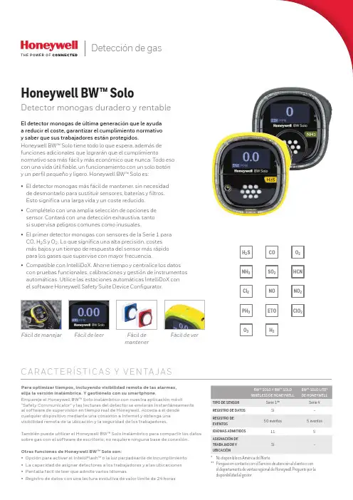
Detección de gasNOETOSO2H2NH3Cl2PH3HCNNO2C l O2H2S O2O3COFácil de manejar Fácil de leer Fácil demantenerFácil de verC A R AC T E RÍS T I C A S Y V E N TA J A SPara optimizar tiempos, incluyendo visibilidad remota de las alarmas,elija la versión inalámbrica. Y gestiónelo con su smartphone.Empareje el Honeywell BW™ Solo inalámbrico con nuestra aplicación móvil"Safety Communicator" y las lecturas del detector se enviarán instantáneamenteal software de supervisión en tiempo real de Honeywell. Acceda a él desdecualquier dispositivo mediante una conexión a Internet y obtenga unavisibilidad remota de la ubicación y la seguridad de los trabajadores.También puede utilizar el Honeywell BW™ Solo inalámbrico para compartir los datossobre gas con el software de escritorio; no requiere ninguna base de conexión.Otras funciones de Honeywell BW™ Solo son:• Opción para activar el IntelliFlash™ o la luz parpadeante de incumplimiento• La capacidad de asignar detectores a los trabajadores y a las ubicaciones• Pantalla fácil de leer que admite varios idiomas• Registro de datos con una lectura evolutiva de valor límite de 24 horasEl detector monogas de última generación que le ayudaa reducir el coste, garantizar el cumplimiento normativoy saber que sus trabajadores están protegidos.Honeywell BW™ Solo tiene todo lo que espera, además defunciones adicionales que lograrán que el cumplimientonormativo sea más fácil y más económico que nunca. Todo esocon una vida útil fiable, un funcionamiento con un solo botóny un perfil pequeño y ligero. Honeywell BW™ Solo es:• El detector monogas más fácil de mantener, sin necesidadde desmontarlo para sustituir sensores, baterías y filtros.Esto significa una larga vida y un coste reducido.• Complételo con una amplia selección de opciones desensor. Contará con una detección exhaustiva, tantosi supervisa peligros comunes como inusuales.CO, H2S y O2. Lo que significa una alta precisión, costesmás bajos y un tiempo de respuesta del sensor más rápidopara los gases que supervise con mayor frecuencia.• Compatible con IntelliDoX. Ahorre tiempo y centralice los datoscon pruebas funcionales, calibraciones y gestión de instrumentosautomáticas. Utilice las estaciones automáticas IntelliDoX conel software Honeywell Safety Suite Device Configurator.Honeywell BW™ SoloDetector monogas duradero y rentableBW™ SOLO Y BW™ SOLOWIRELESS DE HONEYWELLBW™ SOLO LITE*DE HONEYWELLTIPO DE SENSOR Serie 1**Serie 4REGISTRO DE DATOS Sí–REGISTRO DEEVENTOS50 eventos 5 eventosIDIOMAS ADMITIDOS115ASIGNACIÓN DETRABAJADOR YUBICACIÓNSí–* No disponible en América del Norte.** Póngase en contacto con el Servicio de atención al cliente o conel departamento de ventas regional de Honeywell Pregunte por ladisponibilidad al gestor.Honeywell BW™ SoloEspecificaciones técnicasDEBIDO A LA INVESTIGACIÓN CONTINUA Y A LAS MEJORAS CONSTANTES QUE SE APLICAN A LOS PRODUCTOS, LAS ESPECIFICACIONES ESTÁN SUJETAS A CAMBIOS SIN PREVIO AVISO.Datasheet_Honeywell BW Solo_DS110218-01_ES-ES | 11/18© 2018 Honeywell International Inc.* Solamente el Honeywell BW™ Solo Lite (no disponible en América del Norte).SISTEMA DE ACOPLAMIENTO INTELLIDOX IntelliDoX combina los módulos de acoplamiento inteligentes con nuestro sistema de gestión deinstrumentos para proporcionar pruebas automatizadasy facilitar la conservación de registros.Gestión de dispositivos con Honeywell Safety Suite/Safety SuitePara más información Honeywell HPPECra. 11a #98-50, Bogotá, ColombiaTamaulipas 141, 1° Piso, CDMX, México 06140Soporte al Cliente:e-mail:****************************。
目录:水系统传感器 (2)水流开关WFS-1001-H (2)液位开关MAC-3-5M (2)水管式压差传感器P7620C (3)水管式压力传感器P7620A (4)流量变送器8550+2517 (5)VF20T浸入式温度传感器 (5)风系统传感器 (7)DPS系列气流压差开关 (7)DPTM系列压差变送器 (7)风管式温度传感器LF20 (8)风管式温度传感器LF20-C (9)室外温度传感器T7416A1022 (9)室内温度传感器T7412A1000 (9)室内温度传感器CTR21 (10)风管式温湿度传感器H7050B1018 (10)风管式温湿度变送器H7050B1117 (11)室内温湿度变送器H7030A1000 (12)室内温湿度传感变送器H7012B1023 (12)室内温湿度传感器CTR21-H (13)风管式温湿度传感器H7015B1020 (14)室外温湿度传感变送器H7508A1042 (14)CDS2000 系列二氧化碳传感器 (15)C7110C1001(替换已停产的AQS51) 系列二氧化碳传感器 (15)AQS71-KAM(替换已停产的AQS51-KAM) 系列二氧化碳传感器 (16)GD250W3E 系列一氧化碳传感器 (17)C7110A1005系列房间空气质量传感器 (17)L4064K1006B 高温断路开关,手动复位 (18)T6950A1000 低温短路开关,手动复位 (18)数字化挂墙模块T7560 温度传感器 (19)数字化挂墙模块T7460 温度传感器 (19)水系统传感器水流开关 WFS-1001-H应用∙ WFS 水流开关具有SPDT 输出,性能优异,高精度可靠性,可安装在水管和对铜无腐蚀性液体中,当液体流量达到整定速率时,可不到整定点,其一个回路关闭,另一个回路打开,典型应用于连锁作用或断流保护的场所。
∙ WFS 系列开关仅用0℃以上液体介质,它亦可于高盐或氯气的液体,但是非易燃介质。

有限保证和责任限制BW Technologies LP (BW) 保证本产品自交付客户之日起在正常使用和保养情况下两年内不会出现材料和工艺方面的缺陷。
本保证仅适用于原客户购买的、未使用过的新产品。
BW 的保证责任为有限责任,对于在保证期内返回 BW 授权服务中心的缺陷产品,BW 有权自行选择是全额退款、维修还是更换。
在任何情况下,BW 依据本保证承担的责任均不超过客户购买产品时实际支付的价款。
以下情况不属于本担保范围:a)保险丝、一次性电池或使用过程中因产品正常磨损和破损而需要定期更换的零件;b)根据 BW 鉴定,任何因误用、改装、疏忽、意外事故或操作、处理、使用条件异常而损坏的产品;c)任何因非授权经销商维修或在产品上安装了未经许可的零件而造成的损坏或缺陷。
本担保所列出的责任受以下条件限制:a)保管、安装、校准、使用、维护并遵守产品手册说明和 BW 科技有限公司的其他任何应用建议议;b)客户及时就任何产品缺陷通知 BW ,必要时应迅速对产品进行修复。
除非客户收到 BW 的发货指示,否则不能返回任何产品;c)BW 有权要求客户提供购买凭证,如原始发票、销售契约或包装收据,以确定产品是否在保证期内。
客户同意本保证是客户可以获得的唯一补偿,并取代所有其他保证(无论是明示的还是暗含的),包括但不限于对于特殊目的适销性或适合性的任何暗含保证。
不论是由于违背了本保证还是依据合同、侵权行为或信赖或任何其他理论,BW 对特殊、间接、由于某些国家/地区或州/省不允许限制暗含保证的条款,或不允许排除或限制偶然或附带产生的损坏,因此本保证的限制和排除情况可能并不适用于每位客户。
如果本保证的任何规定被有资格的司法管辖法院认为无效或不可执行,将不会影响任何其他规定的有效性或可执行性。
BW Technologies by Honeywell 联系方式电子邮件地址: ********************BW Technologies by Honeywell 网址: 美国: 1-888-749-8878加拿大: 1-800-663-4164欧洲: +44(0) 1295 700300其他国家/地区: +1-403-248-9226珠海司福斯特科技有限w w w .s a f e d t e c h .c o m1GasAlertMax XT II简介本操作员手册提供操作 GasAlertMax XT II 气体检测仪的基本信息。
美国Honeywell霍尔传感器广州南创谭工美国Honeywell流量传感器是一家财富100强公司发明和生产技术,以解决与全球宏观趋势,如安全性,安全性和能源的严峻挑战。
美国Honeywell流量传感器全球约132,000名员工,其中包括超过19,000名工程师和科学家,美国Honeywell霍尔传感器的产品在多个国家设立了国外办事处及售后服务中心,并在中国设立了广州南创传感器事业部,为美国Honeywell流量传感器提供最佳的服务与解决方案。
有质量,交货,价值,和美国Honeywell流量传感器做的一切技术的不懈重点。
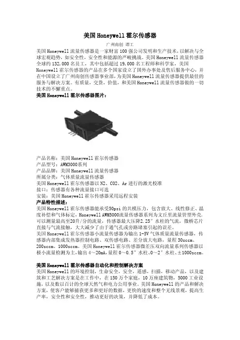
美国Honeywell霍尔传感器图片:产品名称:美国Honeywell霍尔传感器产品型号:AWM3000系列产品品牌:美国Honeywell流量传感器所属分类:气体质量流量传感器美国Honeywell霍尔传感器以N2、CO2、Ar进行的激光校准接口:传感器有各种流量接口可选安装:美国Honeywell霍尔传感器采用远程安装产品特性描述:美国Honeywell霍尔传感器能承受50psi的共模压力,包含放大、线性修正、温度补偿和气体标定,Honeywell AWM5000流量传感器系列为文丘里流量管型外壳,可以测量最高至20升/分的流量,传感器最大压降2.25″水柱的气流,微桥芯片直接与气流接触,大大减少了由于通气孔或旁路堵塞引起的误差。
美国Honeywell霍尔传感器小流量传感器为输出1-5V气体质量流量传感器,传感器内部集成发热器控制电路、双传感电路、差分放大电路,量程30sccm、200sccm、1000sccm。
美国Honeywell霍尔传感器微差压双向流量系列传感器以极小流量检测为主,输出4~20mA,量程0~0.5″水柱、0~2″水柱、±1000sccm。
美国Honeywell霍尔传感器自动化和控制解决方案美国Honeywell的环境控制,生命安全,安全,遥感,扫描,移动产品,以及建筑和工艺解决方案是在工作中,在150万个家庭,10万座建筑物,5000工业设施,以及数以百计的全球天然气和电力公用事业。
HONEYWELL流量传感器AWM系列-文档本公司业代理美国honeywell霍尼韦尔空气质量流量传感器空气质量流量传感器有一个由加热器与温度敏感元件组成的薄膜,隔热的电桥式结构。
该电桥式结构对流过芯片的空气或其他气体流量有灵敏和快速的反应。
电源电压:8Vdc至15Vdc工作温度:-25摄氏度至85摄氏度(-13F-185F)介质相容性:仅限于干燥气体AWM2000系列微桥型空气质量流量传感器是一个无源器件,由2个惠斯通电桥组成,并具有双向传感的能力,按照技术要求,工作时需要一个加热器控制电路,和一个传感电桥馈电电路。
传感器中没有这两个电路,需用户自己设计。
差动放大器是传感电桥一个有用的接口。
它可用来对传感器输出引入增益和电压补偿。
信号调节:非放大型(输出-44,5mVdc至44,5mVdc)压力孔型式:直通型传感器电阻:5K欧流量/压力范围参考型号+_200 sccm AWM2100V+-4.0英寸水柱(10 mBar) AWM2200V+-1000 sccm(1 SLPM)(每分钟1标准升) AWM2300VAWM3000系列如同2000系列,是由双惠斯顿电桥控制空气流量的测量,该AWM3000系列为放大型,所以,它可用来对传感器输出提高增益和引入电压补偿。
加热器控制电路和传感电桥馈电电路都集成在传感器中。
信号调节:放大型(输出1 Vdc至5 Vdc)压力孔型式:直通型流量/压力范围参考型号+_200 sccm AWM3100V+_2.0英寸水柱(5 mBar) AWM3200V+_0.5英寸水柱AWM3201CR+_1000 sccm(1 SLPM) AWM3300V+_1000 sccm(1 SLPM)双向AWM3303VAWM40000系列微桥型空气质量流量传感器根据传热原理工作。
空气质量流量横穿过传感器元件的表面。
输出电压根据通过传感器进出口的空气质量流量或其他气体质量流量成比例地变化。

HoneywellAnalytics©2004 Honeywell Analytics Issue 1 12/2004 MIDAS-A-001目录1 目录 22 概述 53 产品概述 5 3.1 主机架 6 3.1.1 显示器模块 63.1.2 泵模块 7 3.1.3 传感器暗盒腔 73.2 安装托架底座 73.2.1 安装托架 73.2.2 终端模块 73.3 传感器盒 83.3.1 偏致传感器盒 83.4 机壳 84 默认配置 95 安装95.1 探测器的安装和定位 105.2 机械安装 115.3 样品和排气管道计算 125.4 在线过滤器 135.5 本地化探测器选购件 145.6 电气安装 155.7 电连接 17 5.8 改装主机架 185.9 安装传感器盒 196 探测器启动程序 197 总体操作 21 7.1 正常操作模式 217.1.1 重置报警、故障和维护故障 227.2 浏览模式 227.2.1 浏览模式菜单概述 237.3 设置、校准和测试模式概述 247.3.1 设置菜单概述 247.3.2 校准菜单概述‘CAL’ 267.3.3 测试菜单概述‘ tESt’ 278浏览、设置、校准和测试模式子菜单的导向的详细程序 288.1 浏览模式 288.1.1 复查软件‘SW’ 288.1.2 复查报警‘ ALm’ 298.1.3 复查故障‘ FLt’ 298.1.4 复查校准 ‘ CAL’ 298.1.5 复查日期和时间‘timE’ 298.1.6 复查探测器地址‘ nEt’ 308.1.7 复查事件标识‘ Hi St’ 308.2 设置、校准和测试模式 308.2.1 设置菜单‘ SEt’ 318.2.2 设置报警‘ ALm’ 318.2.3 设置故障‘ FLt’ 348.2.4 设置校准间距 ‘ CAL’ 348.2.5 设置日期和时间 ‘timE’ 558.2.6 设置地址‘ nEt’ 358.2.7 设置密码 ‘ PWd’ 368.3 校准菜单‘CAL’ 368.3.1 零点校准 ‘ 0CAL’ 368.3.2 间距校准‘ SPAn’ 378.3.3 流量校准‘ FLoW’ 388.3.4 mA 校准 ‘mA 4-20’ 388.4 测试菜单‘ tESt’ 398.4.1 颠簸测试 ‘ bUmP’ 398.4.2 报警/故障测试‘ Si m’ 398.4.3 禁止状态‘ I nH’ 409 常规维护 41 9.1 传感器盒的更换 419.1.1 传感器盒的安装/更换 419.2 泵的更换 43 9.3 重新组装探测器 469.4 过滤器的更换 4610 热解器模块选项 4710.1 安装热解器模块 4810.2 重新组装MIDAS® 探测器 4911 模拟输出模块 51 11.1 安装模拟模块 5111.2 重新组装MIDAS® 探测器 5212 找出故障并诊断 5313 REFLEX®ٛ5414 内置的网络服务器 5414.1 物理的网络组件 5414.2 网络设置 5414.3 运行网络浏览器 5415 典型安装拓扑 5615.1 常规安装 57 15.2 Modbus/TCP 安装 5715.3 通过以太网供电(POE) 的安装 5716 订购信息 58 16.1 MIDAS® 发送器 5816.2 MIDAS®热解器 5816.2 MIDAS® 热解器 5816.3 MIDAS® 模拟输出模块5816.4 MIDAS®插入式传感器盒(标准保修期) 5916.5 MIDAS®插入式传感器盒(延长保修期)6016.6 完整的MIDAS®气体探测器套件 6116.7 附件及备件 6117 一般规格 6218 校准及颠簸测试 6319 保证声明6720 软件菜单叙述图表 6920.1 高级6920.2 浏览模式7020.3 复查软件的信息、报警、故障及气体校准7120.4 复查日期/时间和网络7220.5 复查事件日志7320.6 设置模式7420.7 设置报警、故障及气体校准 7520.8 设置日期/时间和网络7620.9 设置密码7720.10 校准模式7820.11 校准气体零点及间距7920.12 校准——流量校准 8020.13 校准——4-20 mA 8120.14 测试模式8220.15 测试颠簸、报警/故障模拟 8320.16 测试禁止8421 联系详情 852 概述作为一个提取式气体取样系统,MIDAS气体探测器能在本地或从一个远程点提取一个样品到位于探测器机架内的传感器盒。

DIAGNOSTIC TESTS FOR THE INTELLIGENT GAS SENSORS, iSERIESTechnical NoteHoneywell introduces the Next-Generationintelligent (iseries) gas sensors. These sensorshave a digital interface, longer life andnumerous built-in diagnostics features.The iseries’ intelligent diagnostic features help enhance the overall instrumentperformance, making them smarter and safer by indicating faults and monitoringhealth, thereby decreasing downtime and cost of ownership.The purpose of this document is to describe the Predictive Calibration and End-of-lifefunctions, and outline the principles of the diagnostic tests.BACKGROUNDAll gas sensors drift over time and eventually need recalibrating, and the amountof drift is strongly dependent on the environment that the sensor is used in.Traditionally, instrument developers, fleet managers or end users would work out forthemselves by experience how often they need to recalibrate sensors, or would use recommendations from the sensor or instrument manufacturer as it is not knownwhat conditions the sensors are being used in. This often results in unnecessarilyfrequent recalibrations which is costly and time consuming.Intelligent FeaturesThe iseries platform uses internal tests to monitor the condition of the sensorand apply algorithms both to compensate for drift and to predict when the sensoraccuracy exceeds a predefined limit and needs recalibrating.It can also predict when it is wearing out and can give warning in advance that thesensor needs replacing. As both the Predictive Calibration and End-of-life indicationuse predictions based on the environment that the sensor is being used.Definition of Diagnostic TestsPredictive Calibration: The calibration process can be very tedious, costly and a time-consuming process. With this function, sensors can predict in advance whenits accuracy is becoming too poor to give a reliable reading. This function helps to identify exactly when a recalibration is required.The sensor can estimate the time to recalibration up to six months in advance. Recalibration intervals will be typically at least twice as long as for conventional sensors and will adapt depending on the environment – with sensors used in more benign environments needing less frequent calibrations than those in aggressive ones.The user can configure the accuracy limit of the sensor, and this will determine the interval at which the calibration is needed. In other words, the tighter the accuracy value, the more frequent calibration needed.The user can therefore trade off accuracy against recalibration interval. There is also a configurable built in fixed interval recalibration countdown timer for applications where legislation requires calibration at certain intervals.End-of-Life: The lifespan of a sensor depends mostly on the environmental conditions at which the sensor is exposed. With this function, the sensor can predict in advance when its sensitivity is falling too low to give a reliable and accurate reading. When the End-of-life function is triggered, the sensor automatically warns the instrument via a set of fault flags sent together with the gas reading. If the fault is detected the instrument can warn the user to stop using the sensor.How was the design of the sensor optimised?Honeywell engineers performed finite element analysis of the water management and electrolyte distribution within sensors and gained an extensive understandingof the optimum designs for retaining the electrolyte in the right place at the right concentration.Subsequently, safety operating area charts were developed based on a combination of fundamental physical theory, modelling and experimental verification to show how sensors will perform and withstand over the full temperature, humidity and time.To validate that the sensor will last in real-world applications, an environmental database was obtained. The database contains hundreds of locations around the world, with temperature and humidity data for 10 years with two hourly resolution. The knowledge of use cases for sensors was combined, for example time spent indoors and outdoors, charging to provide input data on the actual conditionssensors are exposed to in the real world. This information was fed into the models to predict how long sensors will last and how their performance will change in real world conditions, and to assist us in optimising the sensor design for maximum performance and life.The environmental performance data was generated by storing sensors in a rangeof environmental conditions over a two-year period. There were more than 8000 individual gas responses recorded for each gas typeDuring this period, the sensors were tested to generate different databases corresponding to the performance of the sensor at particular environments.The resulting predictive algorithm keeps track of the electrolyte concentration and environmental conditions over time and extrapolates this data with a linear regression in order to accurately predict when does the sensor need to be calibrated or when does the sensor is about to reach its lifespan.How does the predictive model for EoL and Predictive Calibration works?To estimate the EoL and Predictive Calibration, a 30-day time period is defined. During this period, the sensor will keep track of the environmental changes. The model works under the assumption that the sensor will be exposed to similar conditions.For instance, if the sensor has been in an extremely hot and dry environment, the predicted model will calculate the corresponding water loss as if the conditions remained the same; giving warning to the user in order to prevent further dry out. Figure 1 shows how the electrolyte concentration and predicted electrolyte concentration vary for a sensor in an extreme environment. The environment chosen corresponds to a challenging environment for the sensor to survive: during winter, outdoor temperatures can be -40°C or less, and in a heated unhumidified buildingor car, the relative humidity can be extremely low due to the very low water content of the cold outside air. Therefore, a sensor which spends part of the day indoors and part outdoors (a typical ‘field worker’ use case) not only gets very dry in winter but is also expected to function at very low temperatures.A perfect prediction (theoretical) would follow the dashed black line. In other words, the predicted days to recalibration would be exactly equal to the actual days to recalibration.The solid black line shows the true electrolyte concentration, which gets dry (high concentration) each winter but recovers to some extent each summer. The yellow line shows how the concentration has been predicted. The historical relative humidityis calculated from the average of another 30 days prior to that. As the prediction is made over a longer time, it becomes less accurate, mainly because the historical environmental conditions become less representative of the future conditions. How often does the sensor updates the EoL and Predictive Calibration?The diagnostic test runs automatically every 24 hours. However, the test is only performed when the sensor is in sleep mode, so it is highly recommended to change the sensor to sleep mode whenever it is not in use (otherwise the End of Life and Predictive Calibration estimations will not be updated/recalculated, leading to non-accurate results).The sensor needs to be in sleep mode at least two minutes per day, so it can update the EoL and Predictive Calibration values.What technique is used for the diagnostic tests?For this test, a smart indicative gadget is used as a diagnostic electrode. Thenan electrochemical technique called square wave voltammetry is applied to the electrode.The technique is a linear potential sweep voltammetry that uses a combined staircase potential and a square wave, which has the advantage of having better peak definition and location than conventional cyclic voltammetry or staircase voltammetry.The diagnostic test is performed to determine the electrolyte concentration of the sensor.Figure 2. Diagnostic TestingHow and when the End-of-Life and Predictive Calibration are flagged?The error and faults can be transmitted to the instrument every time it requests a gas reading from the sensor. For additional information about the gas reading format consult get data pack command (0x30) in the User’s Manual.Predictive Calibration alarm consists of two different parameters, and the • Thealarm will be triggered when either the countdown or the accuracy threshold are reached (whichever is triggered first):o The Predictive Calibration estimation will depend on the requested accuracy of the sensor. This parameter can be configured by the user: the tighter theaccuracy value, the more frequently the calibration.o Additionally, a countdown timer can be set by the user. This period can reflect the time required to calibrate the sensor, which may vary depending on thespecified standard or applications.• Likewise, the End-of-life is flagged when either the countdown or the future prediction algorithm conditions are met (whichever is triggered first):o The predicted End-of-Life algorithm is flagged when the sensor detects less than 50% of its initial sensitivity or when the electrolyte concentrationis above or below its limit. The sensitivity estimation is constantly updatedand its calculation is based on the measure at the minimum temperatures atwhich the sensor has been exposed to.o Along with this, there is a five-year countdown timer. The alarm is flagged after the sensor has reached its expected lifespan.How accurate are the End-of-life andPredictive Calibration functions?The predictive model for End-of-life and time to calibrationis highly accurate if the environmental conditions remainadequately constant.An analogy to this is the ETA (estimated time to arrival) in a car’s GPS system, which is based on previous average speed. If you travel at a constant speed, the ETA will count down linearly and be quite accurate over long distances. However, if you speed up or slow down the ETA could increase of decrease significantly throughout the journey. Similarly, if a sensor is kept in constant conditions, the future prediction based on historical conditions should predict a long way into the future quite accurately, and as a result the time to end of life or recalibration would decrease linearly over time. If the sensor is put into a more aggressive environment, then its predicted time to EOL/ recalibration will start to drop rapidly, whereas if a sensor that has been running in aggressive (e.g. dry) conditions is transferred to more benign conditions, the time to end of life or recalibration prediction may even increase over time.Other diagnostic tests:Just like the End-of-life and Predictive Calibration flags, the sensor can warn the instrument about other possible errors and failures that may appear on a sensor whenever a gas reading command is requested. These flags could also be used to indicate to the end user what type of maintenance is required, for example if the sensor warns that its electrolyte is getting too dry or wet the instrument could advise the user to store it in a suitable humidity environment to recover it.The following table shows the possible failures that the sensor may encounter along with their corresponding automatic detection methods:002717-2-EN | 2 | 08/21HoneywellAdvanced Sensing Technologies 830 East Arapaho Road Richardson, TX 75081FOR MORE INFORMATIONHoneywell Advanced Sensing Technol-ogies services its customers through a worldwide network of sales offices and distributors. For application assistance, current specifications, pricing, or the nearest Authorized Distributor, visit /ast or call:USA/Canada +302 613 4491Latin America +1 305 805 8188Europe +44 1344 238258Japan +81 (0) 3-6730-7152Singapore +65 6355 2828Greater China+86 4006396841WARRANTY/REMEDYHoneywell warrants goods of itsmanufacture as being free of defective materials and faulty workmanship during the applicable warranty period. Honeywell’s standard product warranty applies unless agreed to otherwise by Honeywell in writing; please refer to your order acknowledgment or consult your local sales office for specific warranty details. If warranted goods are returned to Honeywell during the period ofcoverage, Honeywell will repair or replace, at its option, without charge those items that Honeywell, in its sole discretion,finds defective. The foregoing is buyer’s sole remedy and is in lieu of all other warranties, expressed or implied, including those of merchantability and fitness for a particular purpose. In no event shall Honeywell be liable for consequential, special, or indirect damages.While Honeywell may provide application assistance personally, through ourliterature and the Honeywell web site, it is buyer’s sole responsibility to determine the suitability of the product in the application.Specifications may change without notice. The information we supply isbelieved to be accurate and reliable as of this writing. However, Honeywell assumes no responsibility for its use.。

DCXL-DS系列SURSENSE TM超低压压力传感器硅压力传感器描述SURSENSE系列超低压压力传感器采用专利技术,能够降低输出偏差或共模误差。
这系列传感器采用显微机械加工的硅传感元件,该元件具有独特的应力集中-增强结构,可提供与所受压力成比例的高稳定度的线性输出。
与传统的压力传感器相比,因温度变化、受热、长期稳定性和位置敏感性等原因所造成的输出偏移误差已大大降低。
特点DCXL-DS系列传感器提供的mV比例输出,经过精密校准,并具有SURSENSE-增强的稳定性。
每台传感器都经过偏移量、满量程和热误差的校准,提高了流体压力测量的精确度。
这些高稳定的传感器具有符合行业标准装有端口的封装结构,其应力隔离有所改善,适合于安装印刷电路板的应用。
外壳设计采用了连盖板在一起的快速按扣结构,从而提高了产品质量和性能。
本产品获美国国家专利,专利号为6023978。
典型应用●温度补偿0℃至50℃[32℉至122℉] ●可以表压和差压范围供货●线性和滞后总误差<量程的±0.25% ●医疗● HV AC(供热,通风和空调系统)●工业仪表●环境监测DCXL-DS系列SURSENSE TM超低压压力传感器电气规格(25℃[77℉]时12Vdc激励)参数最小值典型值最大值单位Vdc16.0激励电压 3.012.0500零点偏移 -500µVmV21.020.0量程,除DCXL01DS外 19.0mV11.0量程,对DCXL01DS而言 9.010.0-150 - 150 µV偏置温度变化0℃至50℃[32℉至122℉]1,除DCXL01DS外-250 0 250 µV偏置温度变化0℃至50℃[32℉至122℉]1,对DCXL01DS而言-200 0 200 µV量程温度变化0℃至50℃[32℉至122℉]1%量程线性及滞后误差2- 0.05 0.2550[122]-℃[℉][32]补偿温度 0℃[℉]85[185]-工作温度 -25[-13]125[257]℃[℉][-40]-存贮温度 -40偏置受热变化3,除DCXL01DS外 -±50 - µV偏置受热变化3,对于DCXL01DS -±100 - µV偏置位置灵敏度(±1g)DCXL01DS -±50 - µV偏置位置灵敏度(±1g)DCXL05DS,DCXL10DS- ±10 - µV偏置位置灵敏度(±1g)DCXL20DS,DCXL30DS- ±5 - µV注:1.变化相对于25℃[77℉]而言。
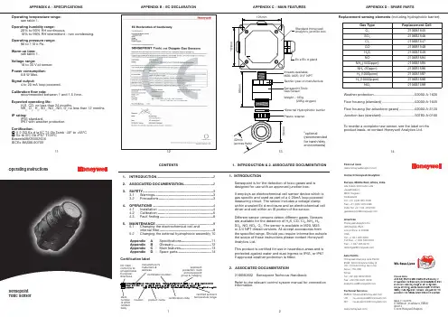
12CONTENTS1. INTRODUCTION .........................................................22. ASSOCIATED DOCUMENTATION ..............................23. SAFETY .......................................................................3 3.1 Warnings ...........................................................3 3.2 Precautions .......................................................34. OPERATIONS .............................................................4 4.1 Installation ........................................................4 4.2 Calibration .. (5)4.3 Fault finding (8)5. MAINTENANCE ..........................................................9 5.1 Changing the electrochemical cell and internal filter ......................................................9 5.2 Changing the external hydrophobic assembly 10 Appendix A - Specifications ..............................11 Appendix B - Glossary ......................................12 Appendix C - Main features . (13)Appendix D-Spare parts (14)APPENDIX A - SPECIFICATIONSAPPENDIX B - EC DECLARATION APPENDIX C - MAIN FEATURESAPPENDIX D - SPARE PARTSmanufacturer’s trademark & addressCE mark - conforms to all applicable European directivescertification numberexplosion protection mark and equipment group & categoryCertification label3745896104. OPERATIONS5. MAINTENANCE4.3FAULT FINDINGSensor reads non-zero all the time:• Gas could be present, ensure that there is no target gas in the atmosphere. Background or other volatile organic gases, eg. solvents, can interfere with the operation of the sensor.Sensor reads non-zero when no gas is present:• adjust the zero on the control card.Sensor reads low when gas is applied:• adjust the span on the control card.• for oxygen versions, check that the neoprene plug has been removed from under the plastic retainer.Sensor reads high when gas is applied:• adjust the span on the control card.Sensor reads zero when gas is applied:• check the wiring.• check the dust protection cap has been removed.• check that the sensor is not obstructed.• replace the sensor if failure is suspected.• for oxygen versions, check that the neoprene plug has been removed from under the plastic retainer.Cannot adjust span or zero at control card:• refer to the technical handbook.5.1 CHANGING ELECTROCHEMICAL CELL ANDINTERNAL FILTER1. Unscrew and remove the grey plastic retainer (or accessory if fitted) from the sensor.2.Remove the old internal hydrophobic assembly bypushing against the snap fit, through one of the retaining slots, with a small flat bladed screwdriver. The assembly will pop out. Do not attempt to lever the assembly out as this may damage the housing.3. Remove the internal metal gauze insert.4.Open the enclosure by unscrewing the sensor capassembly from the sensor main body, ensuring that the electrochemical cell does not rotate with the cap.5a.ToxicGently pull the old electrochemical cell from the pcb. (Dispose of this in accordance with the local regulations).5b.OxygenFor oxygen Sensepoint, unscrew the old cellconnections. Support the screw pillars during removal and refitting of the oxygen cell screws.6. Remove the new cell from its packaging and remove the shorting link across the base of cell.7a. Plug the new cell into the pcb. (toxic cell)7b. Screw in the new cell via the metal tabs. (oxygen cell)8. Screw the sensor cap assembly back onto the sensor main body.9. Fit the new internal metal gauze assembly.10.Fit the new internal hydrophobic assembly.Note: The sensor should now be calibrated. See Section 4.2ATEX SPECIAL CONDITIONS FOR SAFE USEThe detector head must be protected from impact.The detector head must not be used in atmospheres containing greater than 21% oxygen. The integral supply leads must be mechanically protected and terminated in a terminal or junction facility suitable for the areaclassification if the installation. The terminal box and any shrouding metal work (when used) must be effectively earthed. The detector head is considered to present a potential electrostatic risk and must not be located in high air flows or rubbed. The front cover must not be removed when a dust hazard exists and must be fully tightened when replaced. The detector head is designed to be mounted vertically with the gas sensor facing downwards.4.1 INSTALLATIONThe Unit should be fitted to a junction box certified Ex d or Ex e, and fitted with an approved cable gland and connector block. The sensors should be fitted to a tapped hole within the enclosure and locked in place with a locknut if the parallel thread version is being used. Cabling should be multicore, two wires plus screen, conductor size 2.5mm 2 (14AWG) max. Sensors are supplied pre-calibrated.The apparatus should be installed in a location free from dusts and direct heat sources.For optimum protection against water ingress ensure that the sensor is installed facing downwards.Installation is to be performed by a qualified installation engineer, with the power to the unit disconnected.For oxygen versions, remove the neoprene stopper and snap the RFI screen and internal hydrophobic assembly (supplied separately) into place (page 10).See the technical handbook for details of installation in a duct or in forced air conditions.4. OPERATIONS4. OPERATIONS4. OPERATIONS3.1 WARNINGS•T his apparatus is not suitable for use in oxygenenriched atmospheres (>21%V/V). Oxygen deficient atmospheres (<6%V/V) may suppress the sensor output.• Refer to local or national regulations relative to installation at the site.• The operator should be fully aware of the action to be taken if the gas concentration exceeds an alarm level.• The ECC (electrochemical cell) contains a small quantity of acid.• I nstallation should consider not only the best placingfor gas detection related to potential leak points, gas characteristics and ventilation, but also where the potential of mechanical damage is minimized or avoided.• Only assessed by ATEX for ignition hazards• Electrostatic risk - Do not rub or clean with solvents. Clean with a damp cloth. High velocity airflows and dusty environments can cause hazardous electrostatic charges.3.2 CAUTIONS• Exposures to gas above the design range of thesensor may require the sensor to be re-calibrated.•Do not modify or alter the sensor construction as essential safety requirements may be invalidated.• Install Sensepoint using certified Ex e or Ex d junction box, connectors and glanding.•Sensors should be disposed of in accordance with local disposal regulations. Materials used:Sensor: Fortron® (PPS-polyphenylene sulphide), Cell: PPO (modified polyphenylene oxide).• T his equipment is designed and constructed as toprevent ignition sources arising, even in the event of frequent disturbances or equipment operating faults. The electrical input is protected with a fuse.• Do not access the interior of the Sensepoint gas sensor when hazardous (explosive) gas or dust is present. Ensure o-ring is fitted and body is fully tightened when gas cell is replaced.3. SAFETY4.2 CALIBRATIONSensepoint for toxic gas detection is suppliedpre-calibrated, however, for increased accuracy in specific applications, on-site calibration is recommended.Re-calibration should only be attempted by qualified service personnel. Calibration should only be attempted after the sensor has been installed and powered for a time exceeding the warm up time (Table 1).Gas Range Recommended Warm Application Operating Temp.Test up Time MIN. MAX.Concentration TimeH 2S 0 to 20 ppm 10 ppm 3mins 3 mins -20°C +50°C H 2S 0 to 50 ppm 20 ppm3mins 3 mins -20°C +50°C H 2S 0 to 100 ppm 50 ppm3mins 3 mins -20°C +50°C CO0 to 100 ppm 50 ppm3mins 3 mins -20°C +50°C CO 0 to 200 ppm 100 ppm 3mins 3 mins -20°C +50°C CO 0 to 500 ppm 250 ppm 3mins 3 mins -20°C +50°C Cl 2 0 to 5 ppm 3 ppm 5mins 10 mins -20°C +50°C Cl 2 0 to 15 ppm 10 ppm 5mins 10 mins -20°C +50°C O 20 to 25% v/v19% v/v 5mins 1 mins -15°C +40°C NH 3 0 to 50 ppm 25 ppm3mins 10 mins -20°C +40°C NH 3 0 to 1000 ppm 500 ppm3mins 10 mins -20°C +40°C H 2 0 to 1000 ppm 500 ppm 3mins 3 mins -5°C +40°C H 20 to 10000 ppm 3000 ppm3mins 3 mins -5°C+40°CSO 2 0 to 15 ppm 10 ppm 3mins 5 mins -15°C +40°C SO 2 0 to 50 ppm 20 ppm3mins 5 mins -15°C +40°C NO 0 to 100 ppm 50 ppm12hrs 5 mins -5°C+40°CNO 2 0 to 10 ppm5 ppm1hr5 mins-15°C +40°CTable 1:5. MAINTENANCESCREENSCREENSENSORWiring connections are:-The unit requires a nominal 18 to 30V, 30m current-loop-powered supply.First zero the control system with no gas present on the sensor. If target gas is suspected to be in the vicinity of Sensepoint, flow clean air over the sensor using a flow housing (see below).Fit a flow housing and connect a cylinder of either air, for a zero, or a known concentration of gas (approximately 50% FSD) to the flow housing using nylon or PTFE tubing. Tubing lengths should be kept to a minimum to avoidextending the speed of response. Connect the outlet of the flow housing to a safe exhaust area. Pass the gas through the flow housing at a flow rate of approximately1 l to 1.5 l per minute. Allow the sensor to stabilise. When gassing with air, adjust the control card to indicate zero. For span, the control card should be adjusted to indicate the concentration of the target gas being applied. Remove the flow housing and the gas supply.Note: for oxygen, the span gas is normally air at 20.8%v/vO 2. The control card should be adjusted to indicate this when the sensor is in either clean ambient air, or in a flow of 20.8%v/v O 2 in nitrogen from a cylinder. A zero adjustment is not normally required, however it is recommended that the alarm levels are tested using a cylinder of a lower concentration of oxygen in nitrogen.See Table 1 for details of concentrations and times to be used. If the controller cannot be spanned, consult the technical handbook.For calibration using the Weather Protection in high flow applications refer to the technical handbook.Plastic retainerExternal hydrophobic barrier Main body of sensorOxygen cellInternalhydrophobic assembly Sensor cap Toxicelectrochemical cellRFI screen / metal gauze11. Replace the grey plastic retainer or accessory.12. In the event of an apparatus failure, return unit to Honeywell Analytics Ltd.5.2 CHANGING THE EXTERNAL HYDROPHOBIC BARRIERRemove the plastic retainer (or accessory). Remove the old external hydrophobic barrier and replace with the new one. Replace the plastic retainer.4. OPERATIONS。
第五章可燃性气体抠借电路町燃性气体检测报警装置广泛应用在国民经济的各个领域.同时在人们的日常生活中. 在保证家庭安全方面也起到了不可忽视的作用。
本章将对可燃性气体检测报警的基本知识及 i荃实用报警电路进行介绍。
第一节可燃性气体检测报警基本知识-x可燃性r体检测用传感器可燃性气体检测用传想赭乂称为气体传感器或气峨元件,主察用于工业中天然气、煤气、石油化工等部门的易燃、易爆.有毒、有害气体的呛滞,并进行自动控制及安全报警。
二、可燃性气体检测及报畫装■的便用1.气敏元件的安装可燃性气体粉测及报警装置中的主要器件为气救元件.它可以将某种气体浓度的变化转换为由信号并送井善由跌.閃曲.峠峪云件常1方46获口独韭张宜曹口右冷培一木3血出第二节燃气熄火报警电路一、燃气熄火报畫霍燃气灶的火焰如眾发生非正常的熄灭. 往往会形成可燃性气体犬量泄漏〉如未及时发现,将可能发生安全亭故,逍成不必要的拥失「燃气熄火报警器是一个燃气火焰檢测报警电路•如图5・1所示。
火焰检测传想器由光敏电Rt RL担任。
光敏电阻是由半导体材料制成的,当光敏电阻的受光面受到光照作用时.其电导率将发生变化。
无光照射,光戦电阻的阻値很大• 约在1 -100MQ之间.使得流过电路中的电流很小;当有光照射时,光敏电阻的阻值变小.一般在10kC以下。
由于光敏电阻RL与电位器Rh组成分压电路.当燃烧正常时.光敏电阻RL受火焰光线照射而呈现低阻值.它与RR的分压值通过R为半导体管VT|提供足够的旱极电流,使VT•侦和导適.VT,的你申帜輸出低由平.伸抿蜃理曲曲总IC・的伸能地©Jffillta"卜干低由单煤气熄火报警电路如图5・3所示。
恿火探测传想器为两根直径大J1 Imm的金属丝A、B. 亡们的问距为5mm3金处丝探头A、B放1tt在产生火焰的地方,在无火焰时它们足绝缘的. 但往高温F由于空气的电离,A. B间便可导电。
在煤气正常燃烧时.探头A、B间形成导体,Vh和VT2绍成的复合管导通• 1G的触发瑞呈低电平而不工作.其输出端无报警信号. 扬車器无报警声发出。
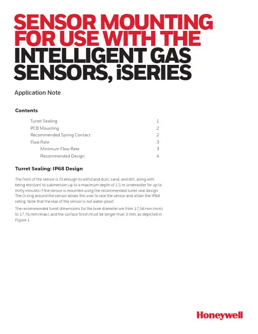
SENSOR MOUNTING FOR USE WITH THE INTELLIGENT GAS SENSORS, iSERIES Application NoteContentsTurret Sealing 1PCB Mounting 2Recommended Spring Contact 2Flow Rate 3Minimum Flow Rate 3Recommended Design 4Turret Sealing: IP68 DesignThe front of the sensor is fit enough to withstand dust, sand, and dirt, along withbeing resistant to submersion up to a maximum depth of 1,5 m underwater for up tothirty minutes if the sensor is mounted using the recommended turret seal design.The O-ring around the sensor allows the user to seal the sensor and attain the IP68rating. Note that the rear of the sensor is not water-proof.The recommended turret dimensions for the bore diameter are from 17,56 mm (min)to 17,76 mm (max), and the surface finish must be longer than 3 mm, as depicted inFigure 1.Figure 1. iseries Sensor (Recommended Turret Dimensions)PCB MountingIf the sensor is mounted inside an instrument, it is required to allow a minimum space height under the cell; this height will depend on the connector. Depending on which of connector is used, the minimum height between the cell and PCB would change. Figure 2. iseries Sensor (Mounted Inside an Instrument)If the sensor is installed inside an instrument, the airpath of the gas is different to access the sensor; likewise, if an additional membrane is used on top of the sensor, the gas diffusion would be different. In general, if the gas dynamics change, the measured concentration value would also change. To compensate for this, it is necessary to change the user factor accordingly.The sensor/instrument coupling can be analysed by Honeywell, so the user factor can be determined accordingly. This would mean that once the user factor is assigned, the sensor would be ready to be set in your instrument (fully calibrated).AØ 17,76D e p e n d a n t o n Recommended spacer to prevent over compression of spring contact: Surface mount resistor size 1206Recommended PCB spring contact:ITT Cannon120220-0310(shown)A-A (1:1)BRecommended Spring ContactUnder no circumstances should intelligent sensor pads be soldered to, as this can cause leakage of electrolyte. Connection should be made via a mounting socket and spring connector., WARNING: SOLDERING TO PADS WILL RENDER YOUR WARRANTY VOID.Details of recommended spring connects are given below:Supplier:UK – CannonVEAM Jays Close, Viables EstateBasingstoke, RG22 4BAphone: +44.1256.311200fax: +44.1256.323356Micro Universal contact: uncompressed height: 1.1 mm, P0.4 SPCManufacturing part number: 120220-0348Flow RateMinimum Flow Rate RequiredA minimum flow rate is required to ensure accurate calibration - it also means that the response from a sensor is equivalent in configurations where gas is flowing over the sensor and those where the sample is allowed to diffuse to the sensor. The minimum flow which is required will be different depending on the sensor type.The reaction mechanism of sensors, consumes target gas - this means that the concentration of target gas will be depleted immediately in front of the sensor.The minimum flow rates are set so that, the sensor is exposed to a constant concentration of target gas - the flow rate is great enough to ensure that this depleted concentration is immediately replaced. This mimics the situation where the sample diffuses to the sensor; there will be a large volume of target gas so that the depletion is immediately replaced - via diffusion.Figure 3.ITT Spring Contact: 120220-0348002738-1-EN | 1 | 08/21HoneywellAdvanced Sensing Technologies 830 East Arapaho Road Richardson, TX 75081FOR MORE INFORMATIONHoneywell Advanced Sensing Technol-ogies services its customers through a worldwide network of sales offices and distributors. For application assistance, current specifications, pricing, or the nearest Authorized Distributor, visit /ast or call:USA/Canada +302 613 4491Latin America +1 305 805 8188Europe +44 1344 238258Japan +81 (0) 3-6730-7152Singapore +65 6355 2828Greater China+86 4006396841WARRANTY/REMEDYHoneywell warrants goods of itsmanufacture as being free of defective materials and faulty workmanship during the applicable warranty period. Honeywell’s standard product warranty applies unless agreed to otherwise by Honeywell in writing; please refer to your order acknowledgment or consult your local sales office for specific warranty details. If warranted goods are returned to Honeywell during the period ofcoverage, Honeywell will repair or replace, at its option, without charge those items that Honeywell, in its sole discretion,finds defective. The foregoing is buyer’s sole remedy and is in lieu of all other warranties, expressed or implied, including those of merchantability and fitness for a particular purpose. In no event shall Honeywell be liable for consequential, special, or indirect damages.While Honeywell may provide application assistance personally, through ourliterature and the Honeywell web site, it is buyer’s sole responsibility to determine the suitability of the product in the application.Specifications may change without notice. The information we supply isbelieved to be accurate and reliable as of this writing. However, Honeywell assumes no responsibility for its use.。
Honeywell传感器广州南创房工Honeywell是一家财富100强公司发明和生产技术,以解决与全球宏观趋势,如安全性,安全性和能源的严峻挑战。
Honeywell传感器全球约132,000名员工,其中包括超过19,000名工程师和科学家,Honeywell传感器的产品在多个国家设立了国外办事处及售后服务中心,并在中国设立了广州南创传感器事业部,为Honeywell传感器提供最佳的服务与解决方案。
有质量,交货,价值,和美国Honeywell传感器做的一切技术的不懈重点。
Honeywell传感器的能力不断提高,来自成功实现两个看似竞争的一次任务 - 生产力和经济增长。
Honeywell传感器公司的核心内部业务流程,传动效率和服务质量。
促成带来世界一流的产品和服务更快地推向市场和更具成本效益自动化和控制解决方案美国Honeywell的环境控制,生命安全,安全,遥感,扫描,移动产品,以及建筑和工艺解决方案是在工作中,在150万个家庭,10万座建筑物,5000工业设施,以及数以百计的全球天然气和电力公用事业。
美国Honeywell的产品和解决方案,使客户能够捕获更多和更好的数据,更快的速度和整个无线景观,提高生产率,安全性和安全性,推动更好的决策,并降低了成本。
航天美国Honeywell流量传感器的航空航天产品和服务用于全球几乎所有的商业和商务飞机经营的今天,以及国防和空间应用。
美国Honeywell提供综合航空电子系统,发动机,系统和服务解决方案,认真听取美国Honeywell的客户和重点放在最能满足他们的需求,使飞行更安全,更可靠,更高效,更具成本效益的技术。
高性能材料和技术以开发和制造先进的材料和工艺技术,是人每天使用,以减少温室气体排放,阻止子弹,使生产的绿色燃料,增加炼油能力,加速药物发现,和保护药品的全球领先地位。
美国Honeywell的先进材料制造尼龙至计算机芯片医药包装产品,以及工艺技术由霍尼韦尔公司的UOP公司的形式大部分世界炼油厂的基础有效地生产汽油,柴油,喷气燃料,石油化工和生物燃料开发的关键。
SS360PT/SS460P内置上拉电阻的高灵敏度锁存型数字霍尔效应传感器集成电路说明SS360PT/SS460P内置上拉电阻的高灵敏度锁存型霍尔效应传感器集成电路结构尺寸小、灵敏度高,借助永磁铁或电磁铁提供的磁场进行工作,可应用于各种不同领域。
它们可对磁场南北极的变换做出响应:SS360PT由北极激活,SS460P由南极激活。
SS360PT/SS460P具有高磁灵敏度(标准值为30 G,,最大值55 G),可提供可靠的切换点。
该传感器集成电路在霍尔元件上并不使用斩波稳定技术,与竞争对手的使用斩波稳定技术的高灵敏度霍尔效应双极锁存型传感器集成电路相比,可提供更清晰的输出信号,获得更快的锁存器响应时间。
内部上拉电阻可以消除传感器对外部组件的需要,帮助客户降低系统成本。
作为经济型的高性能传感器,SS360PT/SS460P 特别适合要求严格、成本敏感的大批量应用。
特点和优势· 在同类产品中有最快的响应速度:使无刷直流电机的换向效率更高· 未使用斩波稳定技术:输出的信号更清晰· 高灵敏度:可在标准30 G、25°C [77°F]的环境下使用;在最大55 G的环境中的使用温度范围可达-40°C至125°C [-40°F至257°F];允许使用更小的磁体或更大的气隙。
· 内部上拉霍尔集成电路设计:简化安装,帮助减少零部件数量和系统成本· 双极锁存型磁性元件:使这些产品非常适用于速度精确感测和RPM测量这些产品具有反向极性保护,在-40 °C至125 °C [-40 °F至257 °F]的温度范围内可输出稳定的信号。
其允许供电电压范围为3 Vdc至24 Vdc(详细信息请参考下面的技术参数部分)。
无刷直流电机制造商需要性能可靠、稳定的锁存型传感器,以实现更高的效率和更小的尺寸设计。
霍尼韦尔压力传感器型号霍尼韦尔压力传感器 142PC01D,142PC02D,142PC03D,142PC05D,142PC15D,142PC30D,142PC15A,142PC30A,142PC30G,141PC01D,141PC02D,141PC03D,141PC05D,141PC15D,141PC30D,143PC01D,143PC02D,143PC03D,143PC05D,143PC15D,143PC30D,141PC01G,141PC02G,141PC05G,142PC01G,142PC02G,142PC03G,142PC05G,142PC15G,163PC01D36,163PC01D48,163PC01D75,164PC01D76,163PC01D37,163PC01D76,161PC01D36,162PC01D36,164PC01D36,189PC15GM,189PC100GM,189PC150GM,ASCX01DN,ASCX05DN,ASCX15AN,ASCX15DN,ASCX30AN,ASCX30DN,ASCX100AN,ASCX100DN,ASCX150DN,ASCX150AN,ASDX015A24R,ASDX030A24R,ASDX100A24R,ASDX001G24R,ASDX005G24R,ASDX015G24R,ASDX020G24R,ASDX100G44R,ASDX001D44R,ASDX005D44R,ASDX015D44R,ASDX030D44R,ASDX100D44R,40PC001G2A, 40PC015G2A, 40PC100G2A, 40PC150G2A, 40PC250G2A, 40PC500G2A, 4040 PC001G2A, 4040PC015G2A, 4040PC100G2 A, 4040PC150G2A, 4040PC250G2A, 4040PC500G2A. 微压传感器 CPCL04DC,CPCL10DC,CPCL04DTC,CPCL10DTC,CPXL04DTC,CPXL10DTC,CPXL01DC,CPXL10DC,XPCL04DC,XPCL10DC,XPCL04DTC,XPCL10DTC,XPX50D,XPXL04DC,XPXL10DC,XPXL04DTC,XPXL10DTC,XSXL04D,XSXL10D,XSCL04DC,XSCL10DC,SDXL005D4,SDXL010D,SLP004D,SLP010D,DCXL01DN,DCXL05DN,DCXL10DN,DCXL20DN,DCXL30DN,DC001NDC4,DC002NDC4,DC005NDC4,DC010NDC4,DC020NDC4,DC030NDC4,DC001NDR4,DC002NDR4,DC005NDR4,DC010NDR4,DC020NDR4,DC030NDR4,DC001NDR5,DC002NDR5,DC005NDR5,DC010NDR5,DC020NDR5,DC030NDR5,DC2R5BDC4,DC005BDC4,DC075BDC4,DUXL01D,DUXL05D,DUXL10D,DUXL20D,DUXL30D。
AWM3000系列是输出为1-5V 的气体质量流量传感器,图1、图2、图3分别为传感器内部的发热器控制电路、双传感电路、差分放大电路图1发热控制电路图2 传感桥供电电路图3 差分放大电路安装尺寸特点:●激光校整保证了一致的互换性● 测量流速可至1.0LPM技术规格:10.0±0.01VDC流量范围(span )压力范围(psi)(参照附录)输出电压@标定点零点电压零点漂移+25~-25˚C +25~+85˚C 输出电压漂移Max +25~-25˚C +25~+85˚C 重复性&迟滞Max电源(VDC )功耗(mW )反应时间(ms )共模压力(psi)工作温度储存温度(˚C )冲击(5drops,6axis)AWM3100V+200sccm5VDC@200sccm1.00±0.05VDC ±25mV-4%读数+4%读数±0.5%读数Min8.0----------25~85˚C -40~90˚C100g 峰值(5drops,6axis)AWM3150V +30sccm3.4VDC@25sccm1.00±0.1VDC±100mV±5.0%读数±5.0%读数± 1%读数Typ.10±0.01501.0---AWM3200V±2.0”水柱5VDC@2”水柱1.00±0.08mV±25mV+24.0%读数-24.0%读数±0.5%读数Max.15 (2)603.0 (1)25AWM3300V +1000sccm5VDC 1000sccm 1.00±0.1VDC±25mV-5%读数+5%读数±1%读数注:1、信号处理最初预热所须时间最多1分钟2、输出电压随电源电压而比率变化3、 差压器件的温漂主要是由气体的浓度随温度而变化气流器件的温漂主要是薄膜TCR 的系数的二次根及厚膜电阻的温飘,加上运放的温飘4、为防止损坏,最大允许流量变化值:5.0SLPM/1.0秒注:正向气流方向被定义为从P 1孔流向P2孔,并导致正的输出,不要施加超过10磅的力在2个测量空孔的每个方向上。
Technical NoteSPI Communication with Honeywell Digital Output Pressure SensorsSensing and Control1.0 IntroductionThe Serial Peripheral Interface (SPI) is a simple bus system for synchronous serial communication between one master and one or more slaves. It operates either in full-duplex or half-duplex mode, allowing communication to happen in either both directions simultaneously, or in only one direction. The master device initiates an information transfer on the bus and generates clock and control signals. Slave devices arecontrolled by the master through individual slave select lines and are active only when selected.Honeywell pressure sensors with SPI output operate in half-duplex mode only, with data transfer from the slave to the master (Figure 1). For this data transmission three lines need to be used:1. Slave Select (SS)2. Signal Clock (SCLK)3. Master In - Slave Out (MISO)These three bus lines are all unidirectional. SCLK and SS and are controlled by the master while MISO is controlled by the slave.2.0 Data Transfer with SPI Output Pressure SensorsStarting communication with Honeywell SPI output pressure sensors begins by deasserting the SS line. At this point, the sensor is no longer idle, and will begin sending data once a clock is received.Honeywell digital output pressure sensors are configured for operation such that data on the MISO line will transition during the falling edge of clock pulses. This means that the data on MISO should be sampled by the master device during the rising edge of the clock pulse.Figure 2 shows an example of a 1 byte data transfer from the slave to the master. In this example, the data 101 (01100101 binary, or 65 hex) would be the result of the read.Figure 2. Example of a 1 Byte SPI Data Transfer withOnce the clocking begins, Honeywell digital output pressure sensors are designed to output up to 4 bytes of data, depending on the sensor options and the needs of the application. In all cases, the first two data bytes are thecompensated pressure output, along with sensor status bits. The third and fourth bytes are for optional compensated temperature output.2.1 Pressure ReadingTo read out a compensated pressure reading, the master generates the necessary clock signal after activating thesensor with the slave select line. The sensor will transmit up to 4 bytes of data – the first two bytes containing thecompensated pressure output, and the second two bytescontaining the optional compensated temperature output. The master can terminate the communication by stopping the clock and deactivating the slave select line. Examples of the communication are shown in Figure 3.SPI Communication with Honeywell Digital Output Pressure Sensors2 Honeywell Sensing and Controlbytes of data. The information contained in these bytes is non-corrected data, and should not be used.2.2 Temperature ReadingThe optional corrected temperature data can be read out with either 8 bit or 11 bit resolution. By reading out the third byte of data from the sensor, the 8 bit compensated temperature value can be read. Further, by reading out the fourth byte of data, the complete 11 bit optional compensated temperature value can be read. The 8 bit value gives an approximate 0.8 ºC resolution, while the 11 bit value gives an approximate 0.1 ºC resolution.When reading the full 11 bit resolution temperature output, the 5 least significant bits of the fourth data byte are “Do Not Care ” and should be ignored.2.3 Status BitsHoneywell digital output pressure sensors offer both standard and optional diagnostics to ensure robust system operation in critical applications. The diagnostic states are indicated by the first two Most Significant Bits of data byte 1.Four diagnostic states are indicated by the 2 status bits (Table 1).This mode should not be seen during normal operation.Standard diagnostics for Honeywell digital output pressure sensors consists of an EEPROM (Electrically ErasableProgrammable Read-Only Memory) signature used to validate the EEPROM contents during startup. In the event that any EEPROM contents change after calibration, a diagnostic condition will be flagged.Optional diagnostics for Honeywell digital output pressure sensors consist of:Loss of sense element connection Short circuit of sense elementSPI Communication with Honeywell Digital Output Pressure SensorsHoneywell Sensing and Control 3When the two status bits are “11”, one of the above mentioned diagnostic faults is indicated.When the status bits read “10”, “s tale” data is indicated , this means that the data that already exists in the sensor’s output buffer has already been fetched by the master, and has not yet been updated with the next data from the current measurement cycle. This can happen when the master polls the data quicker than the sensor can update the output buffer.(Please contact Honeywell Customer Service with questions regarding the availability of optional digital output pressure sensor diagnostics.)3. 0 Calculation of the Pressure from the Digital OutputFor Honeywell digital output pressure sensors, the output of the device can be expressed by the transfer function of the device as shown in Equation 1.Equation 1: Pressure Sensor Transfer Function Output (OutputRearranging this equation to solve for Pressure, we get Equation 2:Equation 2: Pressure Output Function max Pressure (Output (Pressure (OutputWhere:Output max = output at max. pressure [counts] Output min = output at min. pressure [counts]Pressure max = max. value of pressure range [bar, psi, kPa, etc.] Pressure min = min. value of pressure range [bar, psi, kPa, etc.] Pressure = pressure reading [bar, psi, kPa, etc.] Output = digital pressure reading [counts]As an example, the pressure will be calculated for a -1 psi to 1 psi differential sensor with a 10% to 90% calibration and a pressure output of 1657 (decimal) counts:Output max = 14745 counts (90% of 214counts or 0x3999)Output min = 1638 counts (10% of 214counts or 0x0666) Pressuremax= 1 psiPressure min = -1 psiPressure = pressure in psi Output = 1657 counts)1()163814745())1(1()16381657(Pressure)1(13107)2()19(Pressure )1(1310738Pressure)1()002899.0(Pressure997.0Pressure psi 4.0 Calculation of Optional Temperature from the Digital OutputFor Honeywell digital output pressure sensors with the optional compensated temperature output, the output can be converted to degrees C using Equation 3:Equation 3: Temperature Conversion Function 50200Output C)(If the 8 bit temperature output is used, the data must first be shifted left by 3 bits and have the 3 Least Significant Bits set to “0’s ” for the equation to work.As an example, the optional compensated temperature output will be calculated for a sensor with an 8 bit temperature output of 255:Step 1: Left shift the above 8-bit value by 3 places and append the 3 LSBs with 0s:Digital Temperature Output (8 – bit) = 255 = 11111111b 11111111000b = 2040Step 2: Use the adjusted value and plug into Equation 3:5020020472040e Temperatur149.31 e Temperatur ºCAs a second example, the optional compensated temperature output will be calculated for a sensor with an 11 bit temperature output of 1456:Step 1: Plug the digital temperature output value into Equation 3:5020020471456e Temperatur26.92 e Temperatur ºCSPI Communication with Honeywell Digital Output Pressure SensorsSensing and ControlHoneywell1985 Douglas Drive NorthGolden Valley, MN 55422 /sensing 008202-3-ENMay 2012Copyright © 2012 Honeywell International Inc. All rights reserved.5.0 Timing and Level ParametersPERSONAL INJURYDO NOT USE these products as safety or emergency stopWARRANTY/REMEDYHoneywell warrants goods of its manufacture as being free of defective materials and faulty workmanship. Honeywell’s standard product warranty applies unless agreed to otherwise by Honeywell in writing; please refer to your order acknowledgement or consult your local sales office for specific warranty details. If warranted goods are returned to Honeywell during the period of coverage, Honeywell will repair or replace, at its option, without charge those items it finds defective. The foregoing is buyer’s sole reme dy and is in lieu of all other warranties, expressed or implied, including those of merchantability and fitness for a particular purpose. In no event shall Honeywell be liable for consequential, special, or indirect damages.While we provide application assistance personally, through our literature and the Honeywell web site, it is up to the customer to determine the suitability of the product in the application.Specifications may change without notice. The information we supply is believed to be accurate and reliable as of this printing. However, we assume no responsibility for its use.WARNINGMISUSE OF DOCUMENTATIONThe information presented in this technical note sheet is for reference only. DO NOT USE this document as aproduct installation guide.Complete installation, operation, and maintenanceinformation is provided in the instructions supplied witheach product.Failure to comply with these instructions could result in death or serious injury.SALES AND SERVICEHoneywell serves its customers through a worldwide network of sales offices, representatives and distributors. For application assistance, current specifications, pricing or name of the nearest Authorized Distributor, contact your local sales office or:E-mail:*********************Internet: /sensingPhone and Fax:Asia Pacific +65 6355-2828+65 6445-3033 FaxEurope +44 (0) 1698 481481+44 (0) 1698 481676 FaxLatin America +1-305-805-8188+1-305-883-8257 FaxUSA/Canada +1-800-537-6945+1-815-235-6847+1-815-235-6545 Fax。
Honeywell S系列气体传感器使用指南
Honeywell S系列气体传感器使用
1. CLE三电极电化学传感器
对于三电极电化学传感器,每一个电极都有特殊的用途:
感应电极(S),用来氧化或还原气体,并产生与该气体浓度成比例的电流。
参考电极(R),用来稳定感应电极电动势。
对于没有偏压的传感器,感应电极电动势必须与参考电极电动势保持一致。
对于有偏压的传感器,感应电极电动势相对参考电极电动势有一定程度的偏离。
对电极(C),用来还原或氧化感应电极上被氧化或还原的物种,与感应电极一起形成电化学电路。
对电极的电动势允许随着气体浓度的增加而漂移。
对于三电极传感器,其电势是感应电极、参考电极和对电极电势之和。
所有的三电极电化学传感器在推荐的工作气体浓度范围内输出信号与气体浓度成线性关系,可以用下面的公式来计算:
输出信号(uA) = 灵敏度(uA/ppm) ×气体浓度(ppm) 对于无偏压的电化学传感器,感应电极和参考电极的电势差应该为零(<15 mV)。
对电极电动势允许漂移并随着感应电流的产生发生极化。
极化的程度取决于时间和气体浓度。
一旦极化电动势达到1.05 V,对电极就不再极化。
这意味着对一个无偏压电化学传感器,其最大理论电池电压是1.05 V。
对于有偏压的电化学传感器,参考电极和对电极电动势跟无偏压的电化学传感器一样,但是其感应电极电动势和参考电极电动势之差大于零。
推荐的偏压设置为:
ETO: +300 mV;
NH3: +300 mV
NO: +300 mV;
HCl: +200 mV;
O2: -600 mV.
因此,对于有偏压的电化学传感器,其最大理论电池电压是1.35 V。
实际上,在有偏压操作的电化学传感器上,其电池电压一般小于1.2 V。
为了保证Honeywell S系列电化学传感器能正常工作,必须给传感器一个合适的电路。
不论对于无偏压还是有偏压的电化学传感器,感应电极上被氧化的气体,如CO,H2S, PH3, ETO和HCN,其输出信号值是正值,相反的,感应电极上被还原的气体,如NO2和Cl2等,其输出信号值为负值。
为了保证Honeywell S系列无偏压三电极传感器在关闭电源的状态下也处于工作状态,我们用JFET Q1场效应晶体管把感应电极和参考电极短接。
同时,在U1上推荐一个小的偏置电压(<100uV)。
对于有偏压的电化学传感器,感应电极要在比参考电极高的多的电势下工作。
在有偏压的三电极电化学传感器电路中,与感应电极相连接的R load两端的电压不能太大,否则传感器的性能会受到影响。
这个电阻可以在电路噪声和响应时间之间达到一个较好的平衡。
Honeywell S 系列气体传感器使用指南
无偏压电化学传感器:
R load : 负载电阻,参考Honeywell S 系列电化学传感器datasheet 进行设置 R 3: 增益电阻,OUTPUT=输出信号x 增益电阻 Vcc 的典型值: 3.3 V V ref 的典型值: 1.2 V
JEFET Q1 任意可选
. Q1和Q1的控制电压取决于 Vcc, V ref 和栅电压。
带偏压的电化学传感器:
Rload: 负载电阻,参考Honeywell S 系列电化学传感器datasheet 进行设置 R 3: 增益电阻,OUTPUT=输出信号x 增益电阻 Vcc 的典型值: 3.3 V V ref 的典型值: 1.2 V
Honeywell S系列气体传感器使用指南
2. 可燃气体传感器
可燃气体传感器是一种微型催化氧化传感器,用于测量空气中的可燃气体。
可燃气体传感器由一对检测元件和补偿元件组成,每个元件放置于惠斯通电桥的一个桥臂上。
当没有可燃气体存在时,两个元件的电阻相等,电桥平衡,输出信号为零。
当有可燃气体存在时,检测元件将其氧化,产生的热量使其电阻增大,电桥不再平衡,产生与可燃气体浓度成正比关系的输出信号。
目前Honeywell S系列有2.3 V和4.25 V的4系列和7系列两种可燃气体传感器,下图是可燃气体传感器的推荐电路:。