Cisco7200系列路由器的体系结构
- 格式:pdf
- 大小:270.56 KB
- 文档页数:9
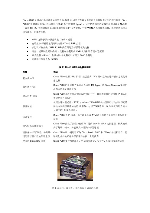
Cisco 7200系列路由器通过其紧凑的外形、模块化、可扩展性以及多种部署选项提供了出色的性价比。
Cisco 7200的处理速度最高可以达到每秒钟40万个数据包(pps),可支持的端口适配器的范围可以从NxDS0一直到OC12,并能够提供无可比拟的全接触IP服务数量,它是WAN边界的理想选择,所提供的功能可以实现以下的部署功能:•WAN边界-获奖的服务质量(QoS)功能•宽带集中-每机箱最高可以处理8000个PPP会话•多协议标签交换(MPLS)PE-供应商边界部署的领先选择•语音、视频和数据集成-可以支持时分复用的VXR机箱和语音端口适配器•IP安全性(IPsec)虚拟专网-每机箱可以扩展到3000个隧道•高端客户单位设备(CPE)表1: Cisco 7200的功能和益处特性优点紧凑的外形Cisco 7200使用3-RU机箱,是层叠式、可扩展中型路由选择解决方案的理想选择领先的性价比Cisco 7200的处理能力最高可以达到400Kpps,是Cisco Systems提供的最强大的单处理器平台领先的IP服务Cisco 7200是进行新功能开发的领先平台,目前所拥有的全接触IP服务的数量是无可比拟的服务加速使用快速转发功能(PXF)的Cisco 7200 NSE-1处理器可以为多种不同的解决方案提供硬件加速的IP服务,包括WAN边界、QoS和宽带用户集中(到2001年第3季度)语音支持Cisco 7200为IP语音、帧中继语音或ATM语音提供了全面的多服务网关功能无与伦比的连接选项Cisco 7200提供了高端口密度和广泛的LAN和WAN连接选项,极大地减少了每端口成本,并能够支持灵活的部署选项投资保护-可扩展性、公共端口适配器以及广泛的部署选项Cisco 7200端口适配器可与Cisco 7400、7500和7600产品线相结合,能够简化备件的贮存并保护客户在接口上的投资全面的Cisco IOS支持 Cisco7200支持网络服务,包括服务质量、安全性、压缩以及高速加密图1 灵活性、模块化、高性能以及紧凑的外形表2: Cisco 7200目标应用和内存应用优点WAN边界Cisco 7200拥有无与伦比的高接触IP服务数量以及硬件加速的WAN边界和QoS服务,是WAN边界连接或集中解决方案的理想选择宽带用户集中Cisco 7200最高可以支持8000个PPP、RBE或L2TP会话,能够在一个紧凑的空间中集中大量的用户,节省了机柜空间并降低了硬件投资成本MPLS PE功能Cisco 7200是一个理想的MPLS PE解决方案,MPLS将路由选择智能与交换性能融合起来,能够扩展现有的网络以满足未来增长的需求。

ubr7200系列路由器体系结构ContentsIntroduction开始使用前ConventionsPrerequisitesComponents Used硬件体系结构机箱概述网络处理引擎和内存输入输出板端口适配器电缆卡启动顺序Related InformationIntroduction本文是Cisco UBR72xx系列路由器的硬件和软件体系结构概述。
开始使用前Conventions有关文档规则的详细信息,请参阅 Cisco 技术提示规则。
Prerequisites本文档没有任何特定的前提条件。
Components UsedThis document is not restricted to specific software and hardware versions.硬件体系结构机箱概述uBR7200系列通用宽带路由器包括Cisco的有线调制解调器终端系统(CMTS)解决方案。
三个不同的机箱是可用的:Cisco uBR7223、Cisco UBR7246和思科uBR7246VXR。
uBR7223 :与传统中平面的一个两slot机箱。
quBR7246 :与传统中平面的四slot机箱。
quBR7246VXR :与VXR盆腔中段平面的四slot机箱。
quBR7223uBR7246uBR7246VXR路由器根据有线数据业务接口规范(DOCSIS)并且支持数据和被数字化的语音连通性在一台双向有线电视和IP骨干网络。
uBR7200系列通用宽带路由器包含:建立接口到无线电频率(RF)电缆装置的有线调制解调器卡。
q连接到IP骨干网和外部网络的端口适配器。
q允许您锁定和传播在路由器中平面的Cisco电缆时钟卡(仅UBR VXR中的T1时钟信号)。
q执行机箱的系统管理功能的一网络处理引擎(NPE)。
q包含一个控制台端口连接数据终端设备的输入-输出(I/O)控制器(DTE),辅助端口连接数据通信q设备(DCE),两个人计算机内存卡国际协会(PCMCIA) slot拥有闪存卡远程装载和存储多个多系统和引导助手镜像,以及提供与网络的100 Mbps连接的一个可选的快速以太网端口。
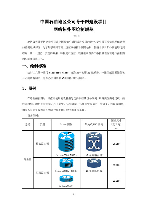
中国石油地区公司骨干网建设项目网络拓扑图绘制规范V2.2地区公司骨干网建设项目是中国石油广域网改进项目的延伸,是中国石油信息基础建设的重要组成部分。
为了加强项目管理,规范网络拓扑图的绘制,使整个项目拓扑图能够达到准确、统一、规范、美观的效果,特制定本规范,项目组成员要严格按照该规范进行拓扑图的绘制和审核工作。
一、绘制标准绘制工具统一使用Microsoft Visio,纸张统一使用A1纸横排。
一张图纸需要涵盖该公司的所有网络,包括办公网络和MES等特殊应用网络。
1、图例在绘制拓扑图时,根据所使用的设备型号选择相应的设备图例,线路类型要通过统一的线条粗细、颜色进行标识。
在下表中,详细列举了拓扑图中包括的一些设备、线路等图例,相关人员需要按照该图例进行拓扑图的绘制和审核工作。
设备图例:链路图例:说明:➢ CPOS 口用一条线连接方框(方框表示SDH ),下连相应设备,呈直折线展开,如果一点下连点数太多,可以将多点平行展开,不要汇聚到一点即可。
如: ➢ ATM 设备一条线连接方框(方框表示ATM ),下连相应设备,呈直折线展开,如果一点下连点数太多,可以将多点平行展开,不要汇聚到一点即可。
如: ➢ 如果在绘制拓扑图的过程中使用了本图例中没有规定的内容,请及时与项目组联系,以便进行统一补充和更新。
2、设备标识针对拓扑图的不同应用可以分为两种:网络设计拓扑图和网络运维拓扑图。
➢ 网络设计拓扑图:应包含设备名称、链路带宽和安装位置。
➢ 网络运维拓扑图:应包含设备名称、Area 域、链路带宽、Loopback 地址、链路互联地址、线路连接接口号等相关信息。
➢ 制图信息:制图信息包含两部分,一部分为制图信息栏,放在拓扑图的右下角;另一部分为图例栏,放在拓扑图的左下角。
两个制图栏都要用线框框起,按整体布局调整线框大小。
拓扑图版本应与文档版本应保持一致。
在图例中应包括拓扑图中所使用的设备和线路示意图。
制图信息栏示例:SDH ATM图例栏示例:二、整体效果拓扑图的最终整体效果要统一,要满足以下几点:➢网络层次明晰,布局合理匀称,稀疏得当。


思科7200系列⽹络处理器家族: NPE-400,NPE-300和NPE-⽹络的规模和功能都在不断发展。
公司每天都在将更多的办公室连接起来并为远程办公和远程⽤户提供更多的连接。
除了增加连接,⽹络供应商还正在⾃⼰的⽹络中添加更多的应⽤和服务。
⽹络服务正在快速成为所有电信服务的重要组成部分。
为提供⾼性能的Internet服务,服务供应商正在创建⼀个⾼级基础结构,以满⾜⾼带宽要求并提供增值服务,如易管理的路由器服务、Web主机托管以及服务质量(QoS)保证。
Cisco 7200系列使企业和服务供应商能够提供⼀系列可扩展的⾼性能多功能路由器,以满⾜不断增长的⽹络需求。
Cisco 7200系列路由器满⾜了对⾼性能、⾼密度、低费效⽐解决⽅案的需求,其中,这些解决⽅案涵盖了数据、语⾳和视频传输应⽤。
作为⽀持这些不同应⽤和⽹络服务的基础,Cisco 7200系列提供了⼀个处理器家族,每种都为获得最优的性能价格⽐⽽进⾏了优化,可以为客户提供⾼性能价格⽐的选项,能够满⾜所有类型的⽹络需求。
Cisco 7200系列Cisco 7204 VXR和Cisco VXR机箱在使⽤NPE-300或NPE-400时,最⾼可提供1Gbps的带宽,并包括了集成多服务交换(MIX)功能。
Cisco 7200系列中可以使⽤的端⼝适配器能够⽀持⼤范围的局域⽹(LAN)和⼴域⽹(WAN)连接。
有关Cisco 7200系列机箱和端⼝适配器的更多信息,请参考"Cisco 7200系列:Cisco⾼性能多功能平台",⽹址为/warp/public/cc/cisco/mkt/core/7200/prodlit/index.shtml。
服务供应商可以更加有利可图地使⽤快速WAN连接在远程提供点为⼤量⽤户提供Layer 3服务⽀持,⽽不必牺牲性能或覆盖范围。
Cisco 7200紧凑的外形和模块化特性使客户能够获得最⼤的密度和可靠性。
Cisco内存体系结构介绍
Cisco路由器的软件部分即网络操作系统。
通过IOS,Cisco路由器可以连接IP,IPX,IBM,DEC,AppleTalk 的网络,并实现许多丰富的网络功能。
软件是需要内存的,Cisco 2500,1600系列路由器的内存体系结构,如图:
其中,ROM相当于PC 机的BIOS,Cisco路由器运行时首先运行ROM中的程序。
该程序主要进行加电自检,对路由器的硬件进行检测。
其次含引导程序及IOS的一个最小子集。
ROM为一种只读存储器,系统掉电程序也不会丢失.
FLASH是一种可擦写、可编程的ROM,FLASH包含IOS及微代码。
可以把它想象和PC机的硬盘功能一样,但其速度快得多。
可以通过写入新版本和OS对路由器进行软件升级。
FLASH中的程序,在系统掉电时不会丢失。
DRAM:动态内存。
该内存中的内容在系统掉电时会完全丢失。
DRAM中主要包含路由表,ARP缓存,
fast-switch缓存,数据包缓存等。
DRAM中也包含有正在执行的路由器配置文件。
NVRAM:NVRAM中包含有路由器配置文件,NVRAM中的内容在系统掉电时不会丢失。
一般地,路由器启动时,首先运行ROM中的程序,进行系统自检及引导,然后运行FLASH中的IOS,并在NVRAM中寻找路由器的配置,并将装入DRAM中。
QoS Classification, Policing, and Marking on aLACThe QoS Classification,Policing,and Marking on a LAC feature allows service providers to classify packetsbased upon the IP type of service(ToS)bits in an embedded IP packet.The classification is used to policethe incoming traffic according to the differentiated services code point(DSCP)value.The purpose ofclassifying the packet by examining its encapsulation is to simplify the implementation and configurationneeded for a large number of PPP sessions.•Finding Feature Information,page1•Prerequisites for QoS Classification Policing and Marking on a LAC,page2•Restrictions for QoS Classification,Policing,and Marking on a LAC,page2•Information About QoS Classification Policing and Marking on a LAC,page2•How to Configure QoS Classification Policing and Marking on a LAC,page4•Configuration Examples for QoS Classification,Policing,and Marking on a LAC,page4•Additional References,page9•Feature Information for QoS Classification Policing and Marking on a LAC,page10Finding Feature InformationYour software release may not support all the features documented in this module.For the latest caveats andfeature information,see Bug Search Tool and the release notes for your platform and software release.Tofind information about the features documented in this module,and to see a list of the releases in which eachfeature is supported,see the feature information table at the end of this module.Use Cisco Feature Navigator to find information about platform support and Cisco software image support.To access Cisco Feature Navigator,go to /go/cfn.An account on is not required.QoS Classification, Policing, and Marking on a LAC Prerequisites for QoS Classification Policing and Marking on a LACPrerequisites for QoS Classification Policing and Marking on a LACConfigure the RoutersYou must configure the client router,the Layer2Tunneling Protocol(L2TP)Access Concentrator(LAC),and the L2TP Network Server(LNS)before applying the QoS policy map as described in the"ConfigurationExamples for QoS Classification,Policing,and Marking on a LAC"section on page4.Verify the State of the Subscriber Service Switch SessionsYou must use the show sss session command to verify that the user sessions are enabled on a LAC.Configure the InterfaceYou must configure the virtual-template interface before applying the policy map to the session. Restrictions for QoS Classification, Policing, and Marking on a LAC•Service-policy on PPP over X.25(PPPoX)interfaces is not supported.•Class-based queueing and class-based shaping are not supported.•Layer2marking is not supported.•The QoS MIB is not supported.•The clear counters command does not clear the counters of the QoS policy map.•Multihop virtual private dialup networks(VPDNs)are not supported.Information About QoS Classification Policing and Marking on a LACBenefits of the QoS Classification Policing and Marking on a LAC Feature •This feature provides policing and marking on a per-session basis for traffic forwarded into L2TP tunnelsto the appropriate LNS and for traffic coming from an L2TP tunnel toward a customer edge router.•This feature helps recognize the IP ToS value in the Point-to-Point Protocol over Ethernet(PPPoE)encapsulated traffic in order to classify and police the traffic according to the DSCP value.QoS Policy Maps and a LACQoS policing and marking can be achieved by attaching a QoS policy map to the user interface on a LAC in the input and output directions.By using tunnels,input and output service policies can be attached to interfaces.Policy maps get enforced as the packet enters or leaves the tunnel.The figure below shows the deployment of QoS on PPPoE sessions originating at the client and terminating at the LNS.Figure 1: Sample Topology for QoS on PPoE SessionsIn this sample topology,the LAC is a Cisco 7200series router.Note Upstream Traffic from the LAC to the LNSUpstream traffic corresponds to packets traversing from the tunnel source to the tunnel destination;in this case,the traffic moves from the LAC to the LNS.The input QoS policy map acts on the upstream traffic before the packet gets encapsulated with the tunnel header.Downstream Traffic from the LNS to the LACDownstream traffic corresponds to packets traversing from the tunnel destination to the tunnel source;in this case,the traffic going from the LNS to the LAC.The output QoS policy map acts on the downstream traffic after the tunnel encapsulation is removed from the packet header.SSS Sessions on the LACThe Subscriber Service Switch (SSS)session provides you with the infrastructure to apply QoS features on a per-session basis.The SSS session is preconfigured on the virtual template,and you can use this template to provide QoS classification,policing,and marking.You can verify the statistics of the upstream and downstream traffic from a QoS policy map in an SSS session by using the show policy-map session command.QoS Classification, Policing, and Marking on a LACQoS Policy Maps and a LACHow to Configure QoS Classification Policing and Marking on a LACEnabling the Service Provider to Verify Traffic StatisticsSUMMARY STEPS1.enable2.show policy-map session [uid uid-number ][input |output [class class-name ]]3.exitDETAILED STEPSPurposeCommand or ActionEnables privileged EXEC mode.enableStep 1Example:Router>enable•Enter your password if prompted.Displays the information about the session identified by the unique ID.show policy-map session [uid uid-number ][input |output [class class-name ]]Example:Router#show policy-map session uid 401outputStep 2(Optional)Exits privileged EXEC mode.exitExample:Router#exitStep 3Configuration Examples for QoS Classification, Policing, and Marking on a LACThe following examples show you how to apply QoS policy maps to upstream and downstream user session traffic to achieve the required Service Level Agreements (SLAs)provided by the service provider.QoS Classification, Policing, and Marking on a LACHow to Configure QoS Classification Policing and Marking on a LACQoS Classification, Policing, and Marking on a LACExample Configuring the RoutersExample Configuring the RoutersThe following example shows the configuration of the routers before the QoS policy map is verified.Client ConfigurationWhen you log in to the PC,a PPPoE session is established at the client that faces the LAC.This PPPoE sessionis forwarded through the L2TP tunnel from the LAC to the LNS at which point the PPPoE session terminates.To apply QoS sessions to the user traffic that originates from the PC to the web server and to the traffic thatoriginates from the web server to the PC,you should apply a QoS policy map to the user session on the LACin the input and output directions.The classification will be based on the user traffic that originates at the PCand the web traffic that originates at the web server.This topology supports bidirectional traffic,meaning that traffic can flow from the PC to the web server andfrom the web server to the PC.username*************password0password1username qos4-72a password0password1username qos4-72b password0password1aaa authentication ppp default localaaa session-id commonip cefvpdn enable!vpdn-group1request-dialinprotocol pppoe!interface ATM0/0/0no ip addressno ip redirectsno ip proxy-arpno ip mroute-cacheload-interval30no atm ilmi-keepalive!interface ATM0/0/0.1point-to-pointpvc0/100encapsulation aal5snappppoe max-sessions100pppoe-client dial-pool-number1!interface Dialer1mtu1492ip address negotiatedencapsulation pppdialer pool1no peer default ip addressno cdp enableppp authentication chap callinppp chap hostname*************ppp chap password0ciscoppp ipcp dns request!LAC ConfigurationThe following example shows that the interfaces between the client and the LAC are ATM5/0interfaces.username*************password0password1username qos4-72a password0password1username qos4-72b password0password1aaa new-modelQoS Classification, Policing, and Marking on a LAC Example Configuring the Routers!!aaa authentication ppp default localaaa session-id commonip cefvpdn enable!vpdn-group1accept-dialinprotocol pppoevirtual-template1!vpdn-group2request-dialinprotocol l2tpdomain initiate-to ip10.10.101.2local name lacno l2tp tunnel authenticationip tos reflect!interface Serial0/0/0bandwidth2015ip address10.10.100.1255.255.255.0no ip redirectsno ip proxy-arpload-interval30no keepaliveno cdp enable!interface ATM0/0/0no ip addressno ip redirectsno ip proxy-arpload-interval30no atm ilmi-keepalive!interface ATM0/0/0.1point-to-pointpvc0/100encapsulation aal5snappppoe max-sessions100protocol ppp Virtual-Template1protocol pppoe!!interface Virtual-Template1mtu1492no ip addressno peer default ip addressppp authentication chap!LNS ConfigurationThe following example shows that the interface between the LAC and the LNS is a Serial3/6interface.username*************password0password1username qos4-72b password0password1username qos4-72a password0password1aaa new-model!!aaa authentication ppp default localaaa session-id commonip cefvpdn enable!vpdn-group1accept-dialinprotocol anyvirtual-template1QoS Classification, Policing, and Marking on a LACExample Verifying the SSS Session terminate-from hostname laclocal name lnslcp renegotiation alwaysno l2tp tunnel authenticationip tos reflect!interface Serial0/0/0bandwidth2015ip address10.10.100.1255.255.255.0no ip redirectsno ip proxy-arpno ip mroute-cacheload-interval30no keepaliveno cdp enable!Example Verifying the SSS SessionThe following example from the show sss session command shows that a user session is enabled on the LAC:Router#show sss sessionCurrent SSS Information:Total sessions1Uniq ID Type State Service Identifier Last Chg401PPPoE/PPP connected Forwarded*************00:02:06Example Applying the QoS Policy MapThe following output shows a QoS policy map to be applied to the user session in the output direction,whichis the downstream traffic coming into the PC from the web server.The first subclass of traffic within thesession is marked with dscp af11,the second subclass is policed,and the third subclass is dropped.class-map match-any customer1234match ip dscp cs1cs2cs3cs4class-map match-any customer56match ip dscp cs5cs6class-map match-any customer7match ip dscp cs7policy-map downstream-policyclass customer1234set ip dscp af11class customer56police cir20000bc10000pir40000be10000conform-action set-dscp-transmit af21exceed-action set-dscp-transmit af22violate-action set-dscp-transmit af23class customer7dropExample Configuring the LACThe following example from the interface virtual-template command shows a QoS policy map being appliedto the user session on the LAC:Router#configure terminalRouter(config)#interface virtual-template1Router(config-if)#service-policy output downstream-policyRouter(config-if)#endExample Verifying the QoS Policy Map for Downstream TrafficIn the following example from the show policy-map session command,the QoS policy map is applied for traffic in the downstreamdirection.The session ID,401,is obtained from the output of the show sss session command shown in the "Example Verifying the SSS Session"section on page 7.NoteRouter#show policy-map session uid 401output SSS session identifier 401-Service-policy output:downstream-policy Class-map:customer1234(match-any)4464packets,249984bytes5minute offered rate 17000bps,drop rate 0bps Match:ip dscp cs1cs2cs3cs44464packets,249984bytes 5minute rate 17000bps QoS Setdscp af11Packets marked 4464Class-map:customer56(match-any)2232packets,124992bytes5minute offered rate 8000bps,drop rate 0bps Match:ip dscp cs5cs62232packets,124992bytes 5minute rate 8000bps police:cir 20000bps,bc 10000bytes pir 40000bps,be 10000bytesconformed 2232packets,124992bytes;actions:set-dscp-transmit af21exceeded 0packets,0bytes;actions:set-dscp-transmit af22violated 0packets,0bytes;actions:set-dscp-transmit af23conformed 8000bps,exceed 0bps,violate 0bps Class-map:customer7(match-any)1116packets,62496bytes5minute offered rate 4000bps,drop rate 4000bps Match:ip dscp cs71116packets,62496bytes 5minute rate 4000bps dropClass-map:class-default (match-any)1236packets,68272bytes5minute offered rate 4000bps,drop rate 0bps Match:anyExample Applying the QoS Policy Map to the SessionIn the following example,the service provider applies a QoS policy map to the user session in order to limit the amount of bandwidth that the user session is permitted to consume in the upstream direction from the PC to the web server:Router#configure terminalRouter(config)#policy-map upstream-policy Router(config-pmap)#class class-defaultRouter(config-pmap-c)#police cir 8000bc 1500be 1500conform-action transmit exceed-action dropRouter(config-if)#endQoS Classification, Policing, and Marking on a LACExample Verifying the QoS Policy Map for Downstream TrafficThis QoS policy map is then applied to the user session as follows:Router#configure terminalRouter(config)#interface virtual-template1Router(config-if)#service-policy input upstream-policy Router(config-if)#endExample Verifying the QoS Policy Map for Upstream TrafficIn the following example from the show policy-map session command,the QoS policy map is applied for traffic in the upstreamdirection:The session ID,401,is obtained from the output of the show sss session command in the "Example Verifying the SSS Session"section on page 7.NoteRouter#show policy-map session uid 401input SSS session identifier 401-Service-policy input:upstream-policy Class-map:class-default (match-any)1920packets,111264bytes5minute offered rate 7000bps,drop rate 5000bps Match:any police:cir 8000bps,bc 1500bytesconformed 488packets,29452bytes;actions:transmitexceeded 1432packets,81812bytes;actions:dropconformed 7000bps,exceed 5000bpsAdditional ReferencesRelated Documents Document TitleRelated TopicCisco IOS Quality of Service Solutions Command Reference QoS commands:complete command syntax,command modes,command history,defaults,usage guidelines,and examples"Applying QoS Features Using the MQC"module Information about attaching policy maps to interfaces using the modular quality of service (QoS)command-line interface (CLI)(MQC)Standards TitleStandard--No new or modified standards are supported,and support for existing standards has not been modified.QoS Classification, Policing, and Marking on a LACExample Verifying the QoS Policy Map for Upstream TrafficMIBs MIBs LinkMIBTo locate and download MIBs for selected platforms,Cisco IOS XE Software releases,and feature sets,useCisco MIB Locator found at the following URL:/go/mibsNo new or modified MIBs are supported,and support for existing MIBs has not been modified.RFCs TitleRFC--No new or modified RFCs are supported,and support for existing RFCs has not been modified.Technical Assistance LinkDescription/cisco/web/support/index.html The Cisco Support and Documentation website provides online resources to download documentation,software,and e these resources to install and configure the software and to troubleshoot and resolve technical issues with Cisco products and technologies.Access to most tools on the Cisco Support andDocumentation website requires a user ID and password.Feature I nformation f or Q oS C lassification P olicing a nd M arking on a LACThe following table provides release information about the feature or features described in this module.This table lists only the software release that introduced support for a given feature in a given software release train.Unless noted otherwise,subsequent releases of that software release train also support that e Cisco Feature Navigator to find information about platform support and Cisco software image support.To access Cisco Feature Navigator,go to /go/cfn .An account on is not required.QoS Classification, Policing, and Marking on a LACFeature Information for QoS Classification Policing and Marking on a LACTable 1: Feature Information for QoS: Classification, Policing, and Marking on a LACFeature InformationReleases Feature Name The QoS:Classification,Policing,and Marking on a LAC featureallows service providers to classifypackets based upon the IP type ofservice (ToS)bits in an embeddedIP packet.The classification is usedto police the incoming trafficaccording to the differentiatedservices code point (DSCP)value.The following command wasintroduced or modified by thisfeature:show policy-map session .Cisco IOS XE Release 2.1QoS:Classification,Policing,and Marking on a LAC QoS: Classification, Policing, and Marking on LAC Configuration Guide, Cisco IOS XE Release 3S11QoS Classification, Policing, and Marking on a LACFeature Information for QoS Classification Policing and Marking on a LACQoS Classification, Policing, and Marking on a LAC Feature Information for QoS Classification Policing and Marking on a LACQoS: Classification, Policing, and Marking on LAC Configuration Guide, Cisco IOS XE Release 3S12。
Cisco 7200、3600 和 2600 路由器上的基于每VC 类的加权公平排队 (Per-VC CBWFQ)目录简介先决条件要求使用的组件规则配置网络图配置示例7200 路由器上的高级 CBWFQ 配置验证故障排除相关信息简介加权公平排队(WFQ)为慢速链路实现(例如序列)为每种流量类型提供公平处理。
要做其工作,WFQ分类流量到根据相关的第三层和第四层信息的不同的流(IP地址, TCP端口,等等)。
您不需要定义访问列表为了此能工作。
使用WFQ,低带宽流量有在高带宽流量的有效优先级。
高带宽流量按比例共享传输介质与分配的权值。
WFQ有以下限制:如果通信流极大增加, WFQ不能调节,因为不可扩展。
qWFQ不是可用的在高速接口,例如ATM。
q新特性,基于类的加权公平排队(CBWFQ),开发寻址WFQ的限制。
不同于WFQ, CBWFQ允许您定义数据流类别。
一旦类定义,参数可能然后应用。
这些参数包括带宽和队列极限。
当曾经CBWFQ时,指定的重要性类变为匹配类标准的重要性每数据包。
此权重来自于您分配到类的带宽。
WFQ然后应用对这些类而不是应用对流。
类能包括几个流。
下面每个vc CBWFQ可用性摘要在7200, 3600和2600路由器的:7200 :Cisco IOS版本12.0(5)T, 12.0(5)XE, 12.1(1), 12.1(1)T, 12.1(1)E和以后使用PA-qA3。
7200与NSE :Cisco IOS版本12.1(7)E和以后。
q7200用NSE-1服务加速器:Cisco IOS版本12.2(4)B1。
q2600/3600与NM-1A-T3/E3模块技术支持LLQ/在Cisco IOS版本12.1(5)T的CBWFQ和以后。
q2600/3600用DS3/E3网络模块:Cisco IOS版本12.1(2)T。
q注意: 思科快速转发功能,因为CBWFQ监控仅经过CEF交换的数据包,必须使用。