astmb456-95电镀标准
- 格式:doc
- 大小:119.00 KB
- 文档页数:12
ASTM名称:B456-95铜/镍/铬和镍/铬电沉积镀层标准规范此标准以固定的名称B456发布,名称后面的数字表示最初采用或最后修订的年份,括号里的数字表示最近重新核准的年份,上标(ε)表示最后修订或再次核准的编辑变更。
此标准已通过国防部的应用核准,有关国防部采纳并发布的确切年份参见规范与标准中DOD索引。
1.范围1.1对于那些重要的金属表面以及重要金属表面的防腐保护,此规范涵盖了几种形式与级别的电沉积物与对应金属或合金的具体要求,这些电沉积物与对应金属或合金包括:钢表面铜镍铬或镍铬镀层、铜和铜合金表面镍铬镀层以及锌合金表面铜镍铬镀层,与希望得到满意保护性能状态相适应的五种镀层级别为:极度恶劣、非常恶劣、恶劣、中度、轻度,这些保护性能的定义和典型例子见附录X1。
1.2以下危险警戒仅适合于试验方法部分此规范中的附录X2,X3及X4中,此标准不声明任何应用中可能涉及到的有关安全方面的问题,使用前,建立适宜的安全和健康规范并确定规则限度的适用性乃标准使用者的责任。
注释1——ISO标准1456和1457不是必需的,但可作为附加信息的参考。
1.参考文献2.1 ASTM标准:B117 操作盐雾试验装置实验B183 电镀用低碳钢配制实验B242 电镀用高碳钢配制实验B252 电镀和电镀层转换锌合金冲模铸造的配制指导B253 电镀用铝合金的配制指导B281 用于电镀和电镀层转换时铜和铜基合金的配制实验B287 醋酸盐雾试验方法B320 铸铁电镀的配制试验B368 铜催化醋酸盐雾试验方法B380 Corrodkote 工艺装饰电沉淀镀层腐蚀试验方法B487 交叉部分显微镜检测的金属和氧化物镀层厚度的测量方法B499 通过磁性方法测得的磁性基底金属表面非磁性镀层的厚度测量之试验方法B504 电量分析法所获金属镀层厚度测量之试验方法B530 磁性方法所获得的镀层厚度测量之试验方法:磁性与非磁性基底表面电沉积镍镀层B537 暴露于大气环境中的电镀板的等级实验B554 非金属基底表面金属镀层厚度测量指导B568 X射线分光光度计所测镀层厚度试验方法B571 金属镀层附着力试验方法B602 金属和无机镀层物的特征取样试验方法B659 金属和无机镀层厚度测量指导B697 电沉积金属和无机镀层检测取样计划的选择指导B762 金属和无机镀层的多种取样方法B764 同时段多层镍沉积物中单层厚度与电气化学电位测定的试验方法D1193 试剂水的规格D3951商业包装惯例E50 装置、试剂和金属的化学分析安全措施的实验B.注释3和4,见第6节2.2 ISO标准ISO 1456金属镀层——镍铬与铜镍铬的电沉积镀层ISO 1457金属镀层——铁或钢表面铜镍铬镀层3.术语3.1 定义3.1.1 重要表面——对外观或正常组装位置上物件的适用性而言,通常必需为可见的表面(直接的或映射的),或因为这些表面而产生组装物件上损坏可见表面的腐蚀性产品,必要时,重要表面应由购买商指定并表明于零件图上或由适当的标记性样本予以提供。

ASTM名称:B456-95铜/镍/铬和镍/铬电沉积镀层标准规范此标准以固定的名称B456发布,名称后面的数字表示最初采用或最后修订的年份,括号里的数字表示最近重新核准的年份,上标(ε)表示最后修订或再次核准的编辑变更。
此标准已通过国防部的应用核准,有关国防部采纳并发布的确切年份参见规范与标准中DOD索引。
1.范围对于那些重要的金属表面以及重要金属表面的防腐保护,此规范涵盖了几种形式与级别的电沉积物与对应金属或合金的具体要求,这些电沉积物与对应金属或合金包括:钢表面铜镍铬或镍铬镀层、铜和铜合金表面镍铬镀层以及锌合金表面铜镍铬镀层,与希望得到满意保护性能状态相适应的五种镀层级别为:极度恶劣、非常恶劣、恶劣、中度、轻度,这些保护性能的定义和典型例子见附录X1。
以下危险警戒仅适合于试验方法部分此规范中的附录X2,X3及X4中,此标准不声明任何应用中可能涉及到的有关安全方面的问题,使用前,建立适宜的安全和健康规范并确定规则限度的适用性乃标准使用者的责任。
注释1——ISO标准1456和1457不是必需的,但可作为附加信息的参考。
1.参考文献ASTM标准:B117 操作盐雾试验装置实验B183 电镀用低碳钢配制实验B242 电镀用高碳钢配制实验B252 电镀和电镀层转换锌合金冲模铸造的配制指导B253 电镀用铝合金的配制指导B281 用于电镀和电镀层转换时铜和铜基合金的配制实验B287 醋酸盐雾试验方法B320 铸铁电镀的配制试验B368 铜催化醋酸盐雾试验方法B380 Corrodkote 工艺装饰电沉淀镀层腐蚀试验方法B487 交叉部分显微镜检测的金属和氧化物镀层厚度的测量方法B499 通过磁性方法测得的磁性基底金属表面非磁性镀层的厚度测量之试验方法B504 电量分析法所获金属镀层厚度测量之试验方法B530 磁性方法所获得的镀层厚度测量之试验方法:磁性与非磁性基底表面电沉积镍镀层B537 暴露于大气环境中的电镀板的等级实验B554 非金属基底表面金属镀层厚度测量指导B568 X射线分光光度计所测镀层厚度试验方法B571 金属镀层附着力试验方法B602 金属和无机镀层物的特征取样试验方法B659 金属和无机镀层厚度测量指导B697 电沉积金属和无机镀层检测取样计划的选择指导B762 金属和无机镀层的多种取样方法B764 同时段多层镍沉积物中单层厚度与电气化学电位测定的试验方法D1193 试剂水的规格D3951商业包装惯例E50 装置、试剂和金属的化学分析安全措施的实验A.铜、锌和铝基底及它的合金B.注释3和4,见第6节ISO标准ISO 1456金属镀层——镍铬与铜镍铬的电沉积镀层ISO 1457金属镀层——铁或钢表面铜镍铬镀层3.术语定义重要表面——对外观或正常组装位置上物件的适用性而言,通常必需为可见的表面(直接的或映射的),或因为这些表面而产生组装物件上损坏可见表面的腐蚀性产品,必要时,重要表面应由购买商指定并表明于零件图上或由适当的标记性样本予以提供。
D 1193Specification for Reagent Water 6D 3951Practice for Commercial Packaging 7E 50Practices for Apparatus,Reagents,and Safety Precau-tions for Chemical Analysis of Metals 82.2ISO Standards:ISO 1456Metallic coatings—Electrodeposited coatings ofnickel plus chromium and of copper plus nickel pluschromium 9ISO 1457Metallic coatings—Electroplated coatings of cop-per plus nickel plus chromium on iron or steel 93.Terminology3.1Definitions:3.1.1significant surfaces —those surfaces normally visible(directly or by reflection)that are essential to the appearance orserviceability of the article when assembled in normal position;or that can be the source of corrosion products that defacevisible surfaces on the assembled article.When necessary,thesignificant surfaces shall be specified by the purchaser andshall be indicated on the drawings of the parts,or by theprovision of suitably marked samples.4.Classification4.1Five grades of coatings designated by service conditionnumbers and several types of coatings defined by classificationnumbers are covered by this specification.4.2Service Condition Number :4.2.1The service condition number indicates the severity ofexposure for which the grade of coating is intended:SC 5extended severe serviceSC 4very severe service,SC 3severe service,SC 2moderate service,andSC 1mild service.4.2.2Typical service conditions for which the variousservice condition numbers are appropriate are given in Appen-dix X1.4.3Coating Classification Number —The coating classifica-tion number comprises:4.3.1The chemical symbol for the basis metal (or for theprincipal metal if an alloy)followed by a slash mark,except inthe case of stainless steel.In this case,the designation shall beSS followed by the designated AISI number followed by aslash,that is,SS463/,4.3.2The chemical symbol for copper (Cu)(if copper isused),4.3.3A number indicating the minimum thickness of thecopper coating in micrometres (if copper is used),4.3.4A lower-case letter designating the type of copperdeposit (if copper is used)(see 4.4and 6.2.3),4.3.5The chemical symbol for nickel (Ni),4.3.6A number indicating the minimum thickness of thenickel coating,in micrometres,4.3.7A lower-case letter designating the type of nickel deposit (see 4.4and 6.2.4),4.3.8The chemical symbol for chromium (Cr),and 4.3.9A letter (or letters)designating the type of chromium deposit and its minimum thickness in micrometres (see 4.4and 6.2.5).4.4Symbols for Expressing Classification —The following lower-case letters shall be used in coating classification num-bers to describe the types of coatings:a —ductile copper deposited from acid-type baths b —single-layer nickel deposited in the fully-bright condition p —dull or semi-bright nickel requiring polishing to give full brightness d —double-or triple-layer nickel coatings r —regular (that is,conventional)chromium mc —microcracked chromium mp —microporous chromium 4.5Example of Complete Classification Numbers —A coat-ing on steel comprising 15µm minimum (ductile acid)copper plus 25µm minimum (duplex)nickel plus 0.25µm minimum (micro-cracked)chromium has the classification number:Fe/Cu15a Ni25d Cr mc (see 4.3and 6.2for explanation of symbols).5.Ordering Information 5.1When ordering articles to be electroplated in conform-ance with this standard,the purchaser shall state the following:5.1.1The ASTM designation number of this standard.5.1.2Either the classification number of the specific coating required (see 4.3)or the substrate material and the service condition number denoting the severity of the conditions it is required to withstand (see 4.2).If the service condition number is quoted and not the classification number,the manufacturer is free to supply any of the types of coatings designated by the classification numbers corresponding to the specified service condition number,as given in Table 1,Table 2,Table 3,or Table 4.On request,the manufacturer shall inform the pur-chaser of the classification number of the coating applied.5.1.3The appearance required,for example,bright,dull,or satin.Alternatively,samples showing the required finish or range of finish shall be supplied or approved by the purchaser.5.1.4The significant surfaces,to be indicated on drawings of the parts,or by the provision of suitably marked specimens (see 3.1).5.1.5The positions on significant surfaces for rack or contact marks,where such marks are unavoidable (see6.1.1).5.1.6The extent to which defects shall be tolerated on nonsignificant surfaces.5.1.7The ductility if other than the standard value (see 6.4).5.1.8The extent of tolerable surface deterioration after corrosion testing (see 6.6.3).5.1.9Sampling methods and acceptance levels (see Section 7).5.1.10The minimum values of the electrochemical potential differences between individual nickel layers as measured in accordance with Test Method B 764within the limits given in 6.7.5.1.11Adhesion Test —The adhesion test to be used (see 6.3).6Annual Book of ASTM Standards ,V ol 11.01.7Annual Book of ASTM Standards ,V ol 15.09.8Annual Book of ASTM Standards ,V ol 03.05.9Available from International Standards Organization,1Rue de Varembe,Geneva 20,Switzerland.6.Product Requirements6.1Visual Defects:6.1.1The significant surfaces of the electroplated article shall be free of clearly visible plating defects,such as blisters, pits,roughness,cracks,and uncoated areas and shall not be stained or discolored.On articles where a visible contact mark is unavoidable,its position shall be specified by the purchaser. The electroplated article shall be clean and free of damage.6.1.2Defects in the surface of the basis metal,such as scratches,porosity,nonconducting inclusions,roll and die marks,cold shuts,and cracks,may adversely affect the appearance and the performance of coatings applied thereto despite the observance of the best electroplating practices. Accordingly,the plater’s responsibility for defects in the coating resulting from such conditions shall be waived.N OTE2—To minimize problems of this type,the specifications cover-ing the basis material or the item to be electroplated should contain appropriate limitations on such basis metal conditions.6.2Process and Coating Requirements:6.2.1Proper preparatory procedures and thorough cleaning of the basis metal surface are essential for satisfactory adhesion and corrosion performance of the coating.Accordingly,the applicable practices for the preparation of various basis metals for electroplating shall be followed.Various ASTM practicesTABLE1Nickel Plus Chromium Coatings on SteelN OTE1—Results of a test program indicate there is some doubt whether the coating systems described by the classification numbers involving regular chromium are satisfactory for SC4and SC3.N OTE2—When permitted by the purchaser,copper may be used as an undercoat for nickel but is not substitutable for any part of the nickel thickness specified.If the use of copper is permitted,Table3may be used to obtain the same service conditions.Service Condition No.Classification No.A Nickel Thickness,µmSC5Fe/Ni35d Cr mc35Fe/Ni35d Cr mp35SC4Fe/Ni40d Cr r40Fe/Ni30d Cr mc30Fe/Ni30d Cr mp30SC3Fe/Ni30d Cr r30Fe/Ni25d Cr mc25Fe/Ni25d Cr mp25Fe/Ni40p Cr r40Fe/Ni30p Cr mc30Fe/Ni30p Cr mp30SC2B Fe/Ni20b Cr r20Fe/Ni15b Cr mc15Fe/Ni15b Cr mp15SC1B Fe/Ni10b Cr r10A When a dull or satinfinish is required,unbuffed p nickel may be substituted for a b nickel or for the bright layer of d nickel.B p or d nickel may be substituted for b nickel in Service Condition Nos.2and 1,and mc or mp chromium may be substituted for r chromium in Service Condition No.1.TABLE2Copper Plus Nickel Plus Chromium Coatings on SteelService ConditionNo.Classification No.A Nickel Thickness,µmSC5Fe/Cu15a Ni30d Cr mc30Fe/Cu15a Ni30d Cr mp30 SC4Fe/Cu15a Ni25d Cr mc25Fe/Cu15a Ni25d Cr mp25 SC3Fe/Cu12a Ni20d Cr mc20Fe/Cu12a Ni20d Cr mp20A When a dull or satinfinish is required,unbuffed p nickel may be substituted for the bright layer of d nickel.TABLE3Copper Plus Nickel Plus Chromium Coatings on ZincAlloyN OTE1—Results of a test program indicate there is some doubt whether the coating systems described by the classification numbers involving regular chromium are satisfactory for SC4and SC3.Service ConditionNo.Classification No.A Nickel Thickness,µmSC5Zn/Cu5Ni35d Cr mc35Zn/Cu5Ni35d Cr mp35SC4Zn/Cu5Ni35d Cr r35Zn/Cu5Ni30d Cr mc30Zn/Cu5Ni30d Cr mp30SC3Zn/Cu5Ni25d Cr r25Zn/Cu5Ni20d Cr mc20Zn/Cu5Ni20d Cr mp20Zn/Cu5Ni35p Cr r35Zn/Cu5Ni25p Cr mc25Zn/Cu5Ni25p Cr mp25SC2B Zn/Cu5Ni20b Cr r20Zn/Cu5Ni15b Cr mc15Zn/Cu5Ni15b Cr mp15SC1B Zn/Cu5Ni10b Cr r10A When a dull or satinfinish is required,unbuffed p nickel may be substituted for b nickel or for the bright layer of d nickel.B p or d nickel may be substituted for b nickel in Service Condition Nos.2and 1,and mc or mp chromium may be substituted for r chromium in Service Condition No.1.TABLE4Nickel Plus Chromium Coatings on Copper or CopperAlloyN OTE1—Although the classification numbers are satisfactory for each of the indicated service condition numbers,systems using microdiscon-tinuous chromium are generally superior in corrosion resistance to those using regular chromium.Service ConditionNo.Classification No.A Nickel Thickness,µmSC4Cu/Ni30d Cr r30Cu/Ni25d Cr mc25Cu/Ni25d Cr mp25SC3Cu/Ni25d Cr r25Cu/Ni20d Cr mc20Cu/Ni20d Cr mp20Cu/Ni25p Cr r25Cu/Ni20p Cr mc20Cu/Ni20p Cr mp20Cu/Ni30b Cr r30Cu/Ni25b Cr mc25Cu/Ni25b Cr mp25SC2B Cu/Ni15b Cr r15Cu/Ni10b Cr mc10Cu/Ni10b Cr mp10SC1B Cu/Ni5b Cr r5A When a dull or satinfinish is required,unbuffed p nickel may be substituted for b nickel or for the bright layer of d nickel.B p or d nickel may be substituted for b nickel in Service Condition Nos.2and 1and mc or mp chromium may be substituted for r chromium in Service Condition No.1.for the preparation of basis metal are available.See Section 2.6.2.2Following the preparatory operations,the parts (ar-ticles)to be electroplated are introduced in such plating bathsas required to produce the types of deposits described by thespecific coating classification numbers or one of the coatingclassification numbers listed in Table 1,Table 2,Table 3,orTable 4appropriate for the specified service condition number.6.2.3Type of Copper and Deposit Thickness :6.2.3.1Type of Copper —The type of copper is designatedby the following symbols that are placed after the thicknessvalue:a for ductile copper deposited from acid-type baths contain-ing additives that promote leveling by the copper deposit andthat have an elongation not less than 8%.No symbol is placed after the thickness value if a minimumelongation is not required or if a deposit from a non-levelingbath is permitted.6.2.3.2Thickness of Copper Deposits —The number follow-ing the chemical symbol for copper (Cu)indicates in microme-tres the minimum thickness of the copper deposit at points onsignificant surfaces (see 3.1).6.2.4Type of Nickel and Deposit Thickness :6.2.4.1Type of Nickel —The type of nickel is designated bythe following symbols,which are placed after the thicknessvalue (Note 5):b for nickel deposited in the fully bright condition.p for dull or semi-bright nickel requiring polishing to give fullbrightness.This nickel shall contain less than 0.005mass %sulfur (Note 3and Note 4),and have an elongation of not lessthan 8%.d for a double-layer or triple-layer nickel coating.Thebottom layer of this coating system shall contain less than0.005mass %sulfur (Note 4),and shall have an elongation ofnot less than 8%.The top layer of this system shall containmore than 0.04mass %sulfur (Note 3and Note 4),and itsthickness shall be not less than 10%of the total nickelthickness;the thickness of the bottom layer in double-layercoatings shall not be less than 60%of the total nickelthickness,except for steel,where it shall be at least 75%.Intriple-layer coatings,the bottom layer shall be not less than50%nor more than 70%.If there are three layers,theintermediate layer shall contain not less than 0.15mass %sulfur and shall not exceed 10%of the total nickel thickness.These requirements for multilayer nickel coatings are summa-rized in Table 5.N OTE 3—The sulfur contents are specified in order to indicate which type of nickel electroplating solution must be used.Although at present,no simple method is available for determining the sulfur content of a nickel deposit on a coated article,chemical determinations are possible using specially prepared test specimens (see Appendix X3).N OTE 4—It will usually be possible to identify the type of nickel by microscopical examination of the polished and etched section of an article prepared in accordance with Test Method B 487.The thickness of the individual nickel layers in double-layer and triple-layer coatings,as well as the electrochemical relationships between the individual layers,can also be measured by the STEP test,10in accordance with Test Method B 764.6.2.4.2Thickness of Nickel Deposit—The number follow-ing the chemical symbol Ni indicates,in micrometres,the minimum thickness of the nickel electrodeposit at points on the significant surface (see 3.1).6.2.5Type of Chromium and Deposit Thickness :6.2.5.1Type of Chromium —The type of chromium deposit is designated by the following symbols placed after the chemical symbol Cr:r for “regular”(that is,conventional)chromium.mc for microcracked chromium,having more than 30cracks/mm in any direction over the whole of the significant surface.The cracks shall be invisible to the unaided eye (see 6.9).mp for microporous chromium containing a minimum of 10000pores/10mm by 10mm square (10000cm 2).The pores shall be invisible to the unaided eye (see 6.9).6.2.5.2Thickness of Chromium Deposit —The minimum thickness of the chromium deposit shall be 0.25µm on significant surfaces (see 3.1),except that for service condition SC 1(see 4.2.1)the minimum thickness may be reduced to 0.13µm.The thickness of chromium is designated by the same symbol as the type instead of by numerals as in the case of copper and nickel.6.2.5.3When plating chromium over microdiscontinuous nickel,excessive thickness will bridge the nonconductive particles within the nickel layer.A maximum of 0.5µm is recommended.6.3Adhesion —The coating shall be sufficiently adherent to the basis metal,and the separate layers of multilayer coatings shall be sufficiently adherent to each other,to pass the appropriate tests detailed in Test Methods B 571.The particular test or tests to be used shall be specified by the purchaser.6.4Ductility —The ductility shall be such that the elonga-tion will not be less than stated in 6.2.3.1for copper and 6.2.4.1for nickel when tested by the method given in Appendix X2.Greater elongation may be requested but shall be subject to10Harbulak, E.P.,“Simultaneous Thickness and Electrochemical PotentialDetermination of Individual Layers in Multilayer Nickel Deposits,”Plating andSurface Finishing ,V ol 67,No.49,February 1980.TABLE 5Summary of the Requirements for Double-and Triple-Layer Nickel CoatingsLayer Type of NickelSpecific Elongation Sulfur Content Thickness Relative to Total Nickel ThicknessDouble-Layer Triple-Layer Steel Other A Steel and Other A Bottom$8%<0.005mass %$75%$60%50–70%Middle (high-sulfur)...>0.15mass %......#10%Top (b)...>0.04mass %10–25%10–40%$30%Test MethodSee Appendix X2Note 3B ......Note 4B ACopper,zinc,and aluminum substrates and their alloys.B For Notes 3and 4,see Section6.agreement between the purchaser and the manufacturer.6.5Coating Thickness :6.5.1The minimum coating thickness shall be as designated by the coating classification number.6.5.2It is recognized that requirements may exist for thicker coatings than are covered by this specification.6.5.3The thickness of a coating and its various layers shallbe measured at points on the significant surfaces (See 3.1andNote 5).N OTE 5—When significant surfaces are involved on which the specifiedthickness of deposit cannot readily be controlled,such as threads,holes,deep recesses,bases of angles,and similar areas,the purchaser and themanufacturer should recognize the necessity for either thicker deposits onthe more accessible surfaces or for special racking.Special racks mayinvolve the use of conforming,auxiliary,or bipolar electrodes or noncon-ducting shields.6.5.3.1The coulometric method described in Test MethodB 504may be used to measure thickness of the chromium,thetotal thickness of the nickel,and the thickness of the copper.The STEP test,Test Method B 764,which is similar to thecoulometric method,may be used to closely estimate thethicknesses of individual layers of nickel in a multilayercoating.6.5.3.2The microscopial method described in Test MethodB 487may be used to measure the thickness of each nickel layer and of the copper layer.6.5.3.3The X-ray method described in Test Method B 568may be used when the total thickness of a copper/nickel/chromium composite coating is to be measured,without any indication of the thickness of each individual layer.6.5.3.4Other methods may be used if it can be demon-strated that the uncertainty of the measurement is less than 10%,or less than that of any applicable method mentioned in 6.5.3.Other methods are outlined in Guide B 659.6.6Corrosion Testing:6.6.1Coated articles shall be subjected to the corrosion test for a period of time that is appropriate for the particular service condition number (or for the service condition number corre-sponding to a specified classification number)as shown in Table 7.The test is described in detail in the referenced ASTM designation.N OTE 6—There is no direct relation between the results of an acceler-ated corrosion test and the resistance to corrosion in other media,becauseseveral factors,such as the formation of protective films,influence theprogress of corrosion and vary greatly with the conditions encountered.The results obtained in the test should,therefore,not be regarded as adirect guide to the corrosion resistance of the tested materials in allenvironments where these materials may be used.Also,performance ofdifferent materials in the test cannot always be taken as a direct guide tothe relative resistance of these materials in service.6.6.2After the article has been subjected to the treatment described in the relevant corrosion test method,it shall be examined for corrosion of the basis metal or blistering of the coating.Any basis metal corrosion or blistering of the coating shall be cause for rejection.It is to be understood that occasional widely scattered,small corrosion defects may be observed after the testing period.In general,“acceptable resistance”shall mean that such defects are not,when viewed critically,significantly defacing or otherwise deleterious to the function of the electroplated part.A method of rating corrosion is given in Practice B 537.6.6.3Surface deterioration of the coating itself is expected to occur during the testing of some types of coatings.The extent to which such surface deterioration will be tolerated shall be specified by the purchaser.6.7STEP Test Requirements:6.7.1The electrochemical potential differences betweenTABLE 7Corrosion Tests Appropriate for Each Service Condition NumberN OTE 1—The so-called “neutral”salt spray test,Practice B 117has been generally discredited as an accelerated corrosion test for decorative nickel-chromium coatings largely because of lack of reproducibility of results.A It is recognized,however,that the test is still used in some segments of the electroplating industry to check the quality of coatings intended for use under relatively mild service conditions.Accordingly,it is suggested that any use of this test and the requirements to be met be the subject of agreement between the purchaser and the manufacturer and,further,that its use be confined to the coatings indicated as appropriate for Service Conditions Nos.2and 1.N OTE 2—The Acetic-salt Method B 287has been discontinued.Basis MetalsService Condition No.Corrosion Test and Duration h CASS Method B 368Corrodkote Method B 380Acetic-salt Method B 287Steel,zinc alloy,SC 544......or copper andSC 422Two 16-h cycles 144copper alloy,SC 3161696stainless steel andSC 24424aluminum alloysSC 1......8A Mendizza,A.,“Standard Salt Spray Test—Is It a Valid Acceptance Test?”Properties,Tests and Performance of Electrodeposited Metallic Coatings,ASTM STP 197,ASTM 1956,p.107.TABLE 6Nickel Plus Chromium A on Stainless Steels,AISIDesignated Type 300and 400Series,B and Aluminum AlloysN OTE 1—Before nickel-chromium plating,the stainless steel surfaceand the aluminum substrate shall be prepared by a pretreatment fromPractice B 254,C Guide B 253,D or equivalent,which is agreed uponbetween the supplier and the user.Service ConditionNo.Classification No.Nickel Thickness,µm SC 4SS-3XX E /Ni20b/Cr mp 20SC 4SS-4xx E /Ni25b/Cr mp 25SC 5Al/Cu15a/Ni40d/Cr mp 40A Data in Table 6were obtained using only microporous chromium systems.Nodata are available for the use of standard or microcracked systems.B The stainless steel alloy numbers used in this specification are based on theAISI system.They may not be interchangeable with other numbering systemssuch as the United Numbering System (UNS)or foreign designations.C Preplate for stainless steel substrates.D Preplate for aluminum substrates.E Insert number for specific 300or 400alloy.individual nickel layers shall be measured for multilayer coatings corresponding to SC5,SC4,and SC3in accordance with Test Method B764(STEP Test).N OTE7—Universally accepted STEP values have not been established but some agreement in the value of ranges has been obtained.The STEP values depend upon which two nickel layers are being measured.The STEP potential difference between the semi-bright nickel layer and the bright nickel layer has a range of100to200mV.For all combinations of nickel layers,the semi-bright nickel layer is more noble(cathodic)than the bright nickel layer.The STEP potential difference between the high-activity nickel layer and the bright nickel layer in triple-layer coatings has a potential range of 15to35mV.The high-activity nickel layer is more active(anodic)than the bright nickel layer.The STEP potential difference between the bright nickel layer and a nickel layer between the bright nickel layer and the chromium layer has a potential range of0to30mV.The bright nickel layer is more active (anodic)than the nickel layer prior to chromium.6.8Sulfur Content:6.8.1The sulfur content of the nickel deposit shall meet the maximum or minimum values as stated in6.2.4.1and Table5.6.8.2Methods for sulfur determinations are given in Appen-dix X3.6.9Density and Measurement of the Discontinuities in Chromium:6.9.1The density of cracks or pores in microcracked or microporous chromium deposits shall meet minimum values. Microcracked chromium shall have more than30cracks/mm (300cracks/cm)in any direction over the whole of the significant surface.Microporous chromium shall contain a minimum of10000pores/10by10mm square(10000 pores/cm2)in any direction over the whole of the significant surface.The cracks and pores shall be invisible to the unaided eye.6.9.2Methods for measuring the discontinuities are given in Appendix X4.See X4.4in Appendix X4for a means of determining active corrosion sites by corrosion testing.7.Sampling Requirements7.1The sampling plan used for the inspection of a quantity of coated articles shall be as agreed upon by the purchaser and supplier.N OTE8—Usually,when a collection of coated articles,the inspection lot(8.2),is examined for compliance with the requirements placed on the coating,a relatively small number of the articles,the sample,is selected at random and is inspected.The inspection lot is then classified as complying or not complying with the requirements based on the results of the inspection of the sample.The size of the sample and the criteria of compliance are determined by the application of statistics.The procedure is known as sampling inspection.Three standards,Test Method B602, Guide B697,and Method B762contain sampling plans that are designed for the sampling inspection of coatings.Test Method B602contains four sampling plans,three for use with tests that are non-destructive and one when they are destructive.The buyer and seller may agree on the plan or plans to be used.If they do not,Test Method B602identifies the plan to used.Guide B697provides a large number of plans and also gives guidance on the selection of a plan.When Guide B697is specified,the buyer and seller need to agree on the plan to be used.Method B762can be used only for coating requirements that have a numerical limit,such as coating thickness.The test must yield a numerical value and certain statistical requirements must be met.Method B762 contains several plans and also gives instructions for calculating plans to meet special needs.The buyer and the seller may agree on the plan or plans to be used.If they do not,B762identifies the plan to be used.N OTE9—When both destructive and nondestructive tests exist for the measurement of a characteristic,the purchaser needs to state which is to be used so the proper sampling plan is selected.A test may destroy the coating but in a noncritical area;or,although it may destroy the coating, a tested part may be reclaimed by stripping and recoating.The purchaser needs to state whether the test is to be considered destructive or nondestructive.7.2An inspection lot shall be defined as a collection of coated articles that are of the same kind,that have been produced to the same specifications,that have been coated by a single supplier at one time or approximately the same time under essentially identical conditions,and that are submitted for acceptance or rejection as a group.7.3If separate test specimens are used to represent the coated articles in a test,the specimens shall be of the nature, size,and number and be processed as required in Appendix X2, Appendix X3,and Appendix X4.Unless a need can be demonstrated,separately prepared specimens shall not be used in place of production items for nondestructive tests and visual examination.For destructive tests including determination of adhesion,ductility,sulfur contents,the number of discontinui-ties,and corrosion testing,separately prepared specimens may be used.8.Packaging8.1Parts plated for the ernment and military, including subcontracts,shall be packaged in accordance with Practice D3951.9.Keywords9.1corrosion;decorative;electrodeposited chromium;elec-trodeposited copper;electrodepositednickelAPPENDIXES(Nonmandatory Information)X1.DEFINITIONS AND EXAMPLES OF SERVICE CONDITIONS FOR WHICH THE V ARIOUS SERVICECONDITION NUMBERS ARE APPROPRIATEX1.1Service Condition No.SC5(Extended Very Severe)—Service conditions that include likely damage from denting, scratching,and abrasive wear in addition to exposure to corrosive environments where long-time protection of the substrate is required;for example,conditions encountered by some exterior components of automobiles.X1.2Condition No.SC4(Very Severe)—Service condi-tions that include likely damage from denting,scratching,and abrasive wear in addition to exposure to corrosive environ-ments;for example,conditions encountered by exterior com-ponents of automobiles and by boatfittings in salt water service.X1.3Service Condition No.SC3(Severe)—Exposure that is likely to include occasional or frequent wetting by rain or dew or possibly strong cleaners and saline solutions;for example,conditions encountered by porch and lawn furniture; bicycle and perambulator parts;hospital furniture andfixtures. X1.4Service Condition No.SC2(Moderate)—Exposure indoors in places where condensation of moisture may occur; for example,in kitchens and bathrooms.X1.5Service Condition No.SC1(Mild)—Exposure in-doors in normally warm,dry atmospheres with coating subject to minimum wear or abrasion.X2.DUCTILITY TESTN OTE X2.1—This test is used to ensure compliance of the type of copper and nickel deposit with the appropriate definition given in6.4. X2.1Preparation of Test Piece:X2.1.1Prepare an electroplated test strip,150mm long,10 mm wide,and1mm thick by the following method:X2.1.1.1Polish a sheet of the appropriate basis metal, similar to that of the articles being electroplated,except that if the basis metal is zinc alloy the sheet may be of soft brass.(Use a sheet sufficiently large to allow the test strip to be cut from its center after trimming off a border25mm wide all around.) Electroplate the polished side of the sheet with copper or nickel to a thickness of25µm under the same conditions and in the same bath as the corresponding articles.X2.1.1.2Cut the test strip from the electroplated sheet with aflat shear.Round or chamfer the longer edges of the strip,at least on the electroplated side,by carefulfiling or grinding. X2.2Procedure—Bend the test strip with the electroplated side in tension(on the outside),by steadily applying pressure, through180°over a mandrel of11.5mm diameter until the two ends of the test strip are parallel.Ensure that contact between the test strip and the mandrel is maintained during bending. X2.3Assessment—The electroplating is deemed to comply with the minimum requirement of an elongation of8%if after testing there are no cracks passing completely across the convex surface.Small cracks at the edges do not signify failure.X3.DETERMINATION OF SULFUR IN ELECTRODEPOSITED NICKEL(NOTE X3.1)The following two methods for the determination of sulfur in electroplated nickel are given as guidelines for use to test compliance of the type of nickel deposit with the appropriate definition given in6.3.2.They represent methods that have been used with success commercially;they are not ASTM standards,nor is it the intent in publishing these methods to preclude the use of other methods or variations in these methods.X3.1Total Sulfur in Electroplated Nickel byCombustion-Iodate TitrationX3.1.1Scope—This method covers the determination of sulfur in concentrations from0.005to0.5mass%.X3.1.2Summary of Method—A major part of the sulfur in the sample is converted to sulfur dioxide(SO2)by combustion in a stream of oxygen using an induction furnace.During the combustion,the SO2is absorbed in an acidified starch-iodide solution and titrated with potassium iodate solution.The latter is standardized against steels of known sulfur content to compensate for characteristics of a given apparatus and for day-to-day variation in the percentage of sulfur recovered as pensation is made for the blank because of accelera-tors and crucibles.N OTE X3.1—Instruments are available for measuring the sulfur dioxide from combustion by infrared detection methods and using built-in computers to integrate and display the sulfur content as a percentage.X3.1.3Interferences—The elements ordinarily present in electroplated nickel do not interfere.X3.1.4Apparatus—Induction heating apparatus for deter-mination of sulfur by direct combustion as described in Practices E50(Apparatus No.13).X3.1.5Reagents:X3.1.5.1Purity of Reagents—Reagent gradechemicals。

铜镍铬合金和镍铬合金电镀涂层的标准说明1. 范围1.1 此标准说明了几种类型和等级的对金属的表面和保护不受侵蚀起很重要作用的涂层的要求,包括镍铬铜合金,钢上的镍铬合金,铜和铜合金上的镍铬合金,300和400类型不锈钢上的镍铬合金,铝和铝合金上的铜镍铬合金和锌上的铜镍铬合金等等.根据能期望提供满意运行的运行条件:也就是,超强,很强,强,中等和轻微的,相应的例出了5个等级的涂层.这些服务条款的定义和具体例子见附件X1.1.2 此标准不涉及塑料电镀的要求,见标准B604.1.3 下列冒险的警告只对测试方法部分,此标准的附件X2,附件X3,附件X4和附件X5: 此标准不支持发表任何关于安全的考虑,如果有,跟它的使用相关. 此标准的使用者对自己的安全和健康负责任并决定法律法规优先于此标准。
2. 参考文件2.1 ASTM 标准:B 183 低炭钢电镀准备的惯例B 242 高炭钢电镀准备指引B 252 锌铝压铸件电镀和变化涂层的准备指引B 253 铝合金电镀准备指引B 254 不锈钢上电镀准备的惯例B 281 铜和铜合金上电镀和交换涂层的准备惯例B 320 铁铸件上电镀准备惯例B 368 铜加速乙酸盐雾试验方法(CASS测试)B 380 克罗德科克程序装饰性电镀涂层侵蚀测试的方法B 487 横截面的金属氧化物涂层厚度的显微镜测量方法.B 489 金属上电镀和自身催化的金属涂层延展性弯曲测试惯例B 490 电镀涂层延展性千分尺弯曲测试惯例B 499 磁方法测量涂层厚度的测试方法: 磁性金属上非磁性涂层B 504库仑定量法测量金属涂层的测试方法B 530 磁方法测量涂层的测试方法: 磁性和非磁性界面的镍涂层B 537 空气暴露下电镀板等级惯例B 568 X线光谱测量涂层厚度的测试方法B 571 金属涂层定性粘附力测试惯例B 602 无机和金属涂层特性样品测试方法B 604塑料上铜镍铬装饰性电镀涂层的标准B 659 金属和无机物涂层厚度测试指导B 697 金属和无机物电镀涂层检测样品计划的选择指导B 762 金属和无机物涂层的可变样品的测试方法B 764 多层镍涂层中单层的厚度和电化学能力同步测试的测试方法D 1193 反应试剂标准D 3951 商业包装惯例E 50 用于金属,矿物和相关材料的化学分析的仪器,试剂和安全注意事项的惯例G 85 改良盐雾测试2.2 ISO 标准ISO 1456 金属涂层--镍铬和铜镍铬合金涂层3. 术语3.1 定义3.1.1 意义层面: 这些层面通常可见(直接或照射),当装配在普通位置时,对物体的外表或,和适用性是非常本质的;它可以是侵蚀的来源,可以在装配物体上损坏外观。

电镀产品检验规范概述电镀是一种将金属物体表面覆盖一层金属薄膜的过程,以改善物体的外观、提高其耐腐蚀性和耐磨损性。
为确保电镀产品的质量,需要进行一系列的检验。
本文将介绍电镀产品检验的规范。
检验项目电镀产品检验主要包括以下几个方面:1. 外观检验:检查电镀表面的平整度、光泽度和色泽是否符合要求。
外观检验还包括检查表面是否有斑点、气泡、氧化物或其他缺陷。
2. 厚度检验:使用合适的仪器测量电镀层的厚度。
厚度检验对于确保电镀层的保护性能至关重要。
3. 粘附力检验:通过针对电镀层施加拉力或剪切力的测试,评估电镀层与基材的粘附力。
粘附力测试可以使用剥离试验或划痕试验。
4. 耐腐蚀性检验:将电镀产品暴露在不同的腐蚀介质中,观察其在一定时间内的耐腐蚀性能。
耐腐蚀性测试通常使用盐雾试验或湿热试验。
5. 硬度检验:测量电镀产品的硬度,以评估其耐磨损性能。
硬度测试可以使用巴氏硬度计或洛氏硬度计。
6. 环保检验:电镀工艺中使用的化学品可能会对环境造成污染。
因此,在电镀产品检验中,也需要进行环保检验,确保电镀过程符合环保要求。
检验标准为确保电镀产品的质量,需要参考一系列的国家标准或行业标准。
以下是一些常用的电镀产品检验标准:1. GB/T 6465-2010《镀层和镀膜边界回流法测量镀层厚度》2. GB/T 10125-2012《环境试验防腐蚀试验盐雾试验》3. GB/T 13329-2014《镀膜硬度测定皮球法》4. GB/T 3189-2018《银电镀件质量》5. ASTM B456-19《Standard Specification for Electrodeposited Coatings of Nickel plus Chromium on Iron and Steel》根据具体的电镀产品及其用途,还可以参考其他相关的标准。
检验流程电镀产品检验的流程一般包括以下几个步骤:1. 取样:从生产批次中随机选取一定数量的样品进行检验。
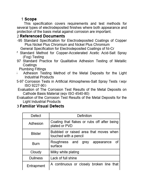
1 ScopeThis specification covers requirements and test methods for several types of electrodeposited finishes where both appearance andprotection of the basis metal against corrosion are important.2 Referenced DocumentsSTM B456-95 Standard Specification for Electrodeposited Coatings of Copper Plus Nickel Plus Chromium and Nickel Plus ChromiumGeneral Specification for Electrodeposited Coatings of Ni-CrM B368-97 Standard Method for Copper-Accelerated Acetic Acid-Salt Spray (Fog) TestingSTM B571-97 Standard Practice for Qualitative Adhesion Testing of Metallic CoatingsSA B125 Plumbing FittingsGB 5933-86 Adhesion Testing Method of the Metal Deposits for the Light Industrial ProductsGB/T 10125-97 Corrosion Tests in Artificial Atmospheres-Salt Spray Tests(eqv ISO 9227-90)Evaluation of The Corrosion Test Results of the Metal Deposits on Cathode Basis Material (eqv ISO 4540-80)Evaluation of the Corrosion Test Results of the Metal Deposits for the Light Industrial Products3 Familiar Visual DefectsDefect DefinitionAdhesion Coating that flakes or rubs off after being plated or PVDBlister Bubbled or raised area that moves when touched with a pencilBurn Roughness and grey appearance of surfaceCloudy Milky white platingDullness Lack of full shineEntrapmentA continuous or closely broken line thatLines appears to be a raised area, but is not loose plating.Glove Snaggers Roughness that breaks off or snags fibers from a clothGross Flaw Any of the defects that can easily be seen more than 900mm away or cause a corrosion failure or interfere with function.Cuts and scratches Scratches due to handling or knocks during transportMissout Area on surface that never received coatingPits Depression in the plated surface Porosity Numerous small closely spaced pitsRoughness Bumpy, rough surface raised and detectable by toughStains/Residue Brown, nonuniform dark shape surface contamination that can be removed by vigorous wipingStardusting Sparkly appearance like small stars or dust on the surfaceTool line Thin raised lines or scratched in base material4 Zone DefinitionA zone:This is the most critical cosmetic article of the part. The A zoneis usually the most striking feature. It is what the customer seesfirst or is closest to the customer in the installed position.B zone:These features are important but further removed from thecustomer. B zone surface are easy to see in the installedposition.C zone:These are the least important features in areas not directlyseen. Often, you must move your head or the product asignificant amount to see C zones in the installed position.D zone:These zones are not important and can not be seen at all after installation.On the D zones of the electroplated article where the follow defects are acceptable:Pit, porosity, roughness, stardusting, cuts and scratches, tool lines, gross flaws, rough plating, cloudy plating, stains, burns, missout, blisters. Adhesion failures such as cracks and peeling plate shall be avoided.5 Appearance Criteriadefect Accept criterionaestheticA zoneB zoneC zonepits、roughplating、cuts andscratchesRoundnessdefect maxsize0.1mm20.2mm20.4mm2The maxspace toeach other19 mm13mm3mmAcceptableamount234 burnsIf felt and not seen in the installedpositionCloudyplatingPer visualcontrolsampleslightA few moderate porositystardustingTool line rejectEntrapment Lines RejectOneallowedin thezoneup to13mmTwo allowed inthe zone up to13mm maxsize, no closerthan 3mm tomaxsizeeach other.Discolored Pertone color is OK providing that both are within the range and the difference is not seen in assembled/installed position.stained reject reject rejectfunctional Adhesion failurereject reject reject blisterGross flawGlove snaggermissout6 Functional Requirement6.1 DimensionThe import dimensions and connect threads shall be comply with the drawing.6.2 Deposit Thickness RequirementThicknessOn copper On zinc alloys Copper/≥5μmNickel≥7.6μm≥10μmChromium≥0.25μm≥0.25μmAurum About 0.15μm,the articles shall not discoloredper the control samples.Remark:1. Plating thickness shall be determined by measuring thickness of three typical areas on the article. These should include low/high current density areas. The average of the measurements shall not less than the above thickness.2. Unless client have stress the plating thickness in particular, the nickel and copper plating thickness can be regulated base on the corrosion test and thermal cycle test..6.3 Corrosion Testing RequirementCASS8HAASS24HRequirement 1. After the corrosion testing, the articles shallcomply with CSA B125 Clause 6.1.3:The article shall not exhibit more than one corrosion spot per 645 mm2of surface area, except that up to three minor spots may be permitted on a 25 mm length of parts line. Spots shall not be more than 0.8 mm in any dimension. 2. After the corrosion testing, the article shall the 9th grade criteria in GB64616.3 Adhesion requirementThe Test Method Requirement1) Head the coated copper article in an oven to reach the temperature of 250℃±10℃. Maintain the temperature for 1 hour, then quench the part in water at the temperature of Flaking or peeling of the deposit is evidence of unsatisfactory adhesion. Blisters may erupt during the head and quench test when plating solution is entrapped in substrate surface18℃-25℃。
目录1.工艺鉴定要求 (4)1.1.总则 (4)1.2.设计要求 (4)1.3.工艺鉴定程序 (4)1.4.工艺鉴定试验及试样要求 (4)1.4.1.试样要求 (4)1.4.2.试验项目及试样数量 (4)1.5.试验方法及质量指标 (5)1.5.1.外观 (5)1.5.2.镀层厚度 (5)1.5.3.结合强度 (5)1.5.4.耐蚀性 (5)1.6.鉴定状态的保持 (5)2.批生产检验要求 (5)2.1.镀前表面质量要求 (5)2.2.镀层外观 (5)2.3.镀层厚度 (6)2.4.结合强度 (6)2.5.耐蚀性 (6)错误!未找到引用源。
范围:本规范规定了华为技术有限公司产品的钢、铜、锌合金等金属基体零件上镀装饰铬的工艺要求及其质量要求。
本规范适用于装饰镀铬的工艺鉴定和批生产质量检验。
简介:本规范分两部分,第一部分“工艺鉴定要求”规定了加工商必须保证的技术管理、工艺设施及产品质量水平要求,用作对供应商进行技术资格认证和首样质量鉴定,是华为对装饰镀铬零件进行质量鉴定的依据;第二部分规定了正常批生产条件下产品质量要求,是生产方控制批生产镀层质量的标准依据,也是产品验收的质量依据。
关键词:镀铬,镀层,耐蚀性引用文件:下列文件中的条款通过本规范的引用而成为本规范的条款。
凡是注日期的引用文件,其随后所有的修改单(不包括勘误的内容)或修订版均不适用于本规范,然而,鼓励根据本规范达成协议的各方研究是否可使用这些文件的术语和定义:1. 工艺鉴定要求1.1. 总则在对供应商进行工艺技术资格认证时、或者供应商有新产品首次生产时必须按本节要求进行工艺质量鉴定。
原则上,已经鉴定过的材料、工艺只需要提供相关报告。
生产者的工艺质量必须满足第1节的要求。
生产者的工艺设备、工艺流程、质量保证措施应在其主要的工艺文件中加以说明。
1.2. 设计要求按本规范要求进行的装饰镀铬工艺,对钢铁基体必须是电镀铜-镍-铬的工艺。
生产者应保持并遵守经华为技术有限公司(以下简称“华为”)正式批准的工艺和检验文件。
金属电镀件检验标准(CA级英文版)Specification of Plating on Basis Metals1 ScopeThis specification covers requirements and test methods for several types of electrodeposited finishes where both appearance and protection of the basis metal against corrosion are important.2 Referenced DocumentsASTM B456-95 Standard Specification for Electrodeposited Coatings of Copper Plus Nickel Plus Chromium and Nickel Plus ChromiumEN248-2002 General Specification for Electrodeposited Coatings of Ni-CrASTM B368-97 Standard Method for Copper-Accelerated Acetic Acid-Salt Spray (Fog) Testing ASTM B571-97 Standard Practice for Qualitative Adhesion Testing of Metallic CoatingsCSA B125 Plumbing FittingsGB 5933-86 Adhesion Testing Method of the Metal Deposits for the Light Industrial Products GB/T 10125-97 Corrosion Tests in Artificial Atmospheres-Salt Spray Tests(eqv ISO 9227-90)GB6461-86 Evaluation of The Corrosion Test Results of the Metal Deposits on Cathode Basis Material (eqv ISO 4540-80)GB5944-86 Evaluation of the Corrosion T est Results of the Metal Deposits for the Light Industrial Products3 Familiar Visual Defects4 Zone DefinitionA zone:This is the most critical cosmetic article of the part. The A zone is usually the most strikingfeature. It is what the customer sees first or is closest to the customer in the installed position.B zone:These features are important but further removed from the customer. B zone surface are easyto see in the installed position.C zone:These are the least important features in areas not directly seen. Often, you must move yourhead or the product a significant amount to see C zones in the installed position.D zone:These zones are not important and can not be seen at all after installation.On the D zones of the electroplated article where the follow defects are acceptable:Pit, porosity, roughness, stardusting, cuts and scratches, tool lines, gross flaws, rough plating, cloudy plating, stains, burns, missout, blisters. Adhesion failures such as cracks and peeling plate shall be avoided.6 Functional Requirement6.1 DimensionThe import dimensions and connect threads shall be comply with the drawing.6.2 Deposit Thickness Requirement7.Inspect method7.1 Appearance Inspect7.1.1 Hold the articles as installed position to inspect for aesthetic defects. Determine the article compliance with appearance criteria. The other inspects condition:a)The observer shall have 20/20 vision at a distance of 600 to 900 mm, corrected with eyeglasses if necessary.b) Using two 40W diffused daylight-type fluorescent lighting, THE DISTANCE between thelighting and article shall be 1000 mm. At the surface of the article being inspected, the lighteness shall be 1500 to 1600 lm/m2.c) The article shall be evaluated at a distance of not less than 300 mm nor more than 400 mmfrom the observer.d) The observe time:A zone 6s, B zone 4s、C zone 2s。
ASTM文件编号:B604-91(1997年重新认可)表面处理资料塑料件电镀涂装铜+镍+铬标准规范本标准在固定文件编号B604之下发行,文件编号之后的数字是本年采用的编号,或者万一有修改,则为本年最后修改版本。
括号中的编号表示本年最终认可编号。
上标E指最后修改或重新认可的变更。
1、范围1.1 本规范涉及的要求用于电镀铜+镍+铬塑料素材的几种等级和类型,而这些素材的外观,耐用性和热循环都对服务性能非常重要。
将提供此条件的五个等级涂装,每一个都希望能达到满意的性能。
1.2 本规范涉及使用的涂装要求,是在应用自动角媒的金属膜之后使用的,或者在应用自动触媒后任何涂装的应用之后使用的。
1.3 以下只属于此规范测试方法的笫六部分,附录A1,附录X2,附录X3和附录X4。
本标准不是旨在说明所有安全问题,如有,则是关于其使用上的。
本标准的使用者责任在于使用前建立一套合适的安全健康的条例,决定规格限制的可使用性。
2 参考文献2.1 ASTM标准:B 368 方法用于铜加速盐雾试验(CASS试验)B 487 试验方法用于交叉部分检验金属和氧气涂装厚度的测量B 489 条例用于金属涂装电镀和自动触媒延展性的弯曲试验B 504 试验方法金属涂装厚度的测量B 530试验方法用磁性的方法测量涂装厚度:磁性的非磁性素材的镀镍涂装B 532 规范用于电镀塑料表面或外观B 533试验方法用于电镀金属塑料件脱层强度B 556 指南用于通过斑点测试对薄铬层的测量B 567 试验方法用于通过Beta Backscatter方法测量涂装厚度B 568试验方法用于通过X光谱测量涂装厚度B 602 试验方法用于金属和非有机涂装样件性能B 659 指南用于金属和非有机涂装厚度测量B 727 条例用于电镀塑料材料的准备B 764 试验方法用于多层电镀镍中单层厚度和电化学潜力的决定(STEP试验)D 1193 试剂规范E 50 条例用于金属化学分析的仪器,试剂和安全防护措施3 术语3.1 定义3.1.1 重要表面———通常为可视表面(直射或反射),当正常装车后损坏表面的产品来源时,对产品的外观或服务性能起重要作用的表面。
ASTM名称:B456-95铜/镍/铬和镍/铬电沉积镀层标准规范此标准以固定的名称B456发布,名称后面的数字表示最初采用或最后修订的年份,括号里的数字表示最近重新核准的年份,上标(ε)表示最后修订或再次核准的编辑变更。
此标准已通过国防部的应用核准,有关国防部采纳并发布的确切年份参见规范与标准中DOD索引。
1.范围对于那些重要的金属表面以及重要金属表面的防腐保护,此规范涵盖了几种形式与级别的电沉积物与对应金属或合金的具体要求,这些电沉积物与对应金属或合金包括:钢表面铜镍铬或镍铬镀层、铜和铜合金表面镍铬镀层以及锌合金表面铜镍铬镀层,与希望得到满意保护性能状态相适应的五种镀层级别为:极度恶劣、非常恶劣、恶劣、中度、轻度,这些保护性能的定义和典型例子见附录X1。
以下危险警戒仅适合于试验方法部分此规范中的附录X2,X3及X4中,此标准不声明任何应用中可能涉及到的有关安全方面的问题,使用前,建立适宜的安全和健康规范并确定规则限度的适用性乃标准使用者的责任。
注释1——ISO标准1456和1457不是必需的,但可作为附加信息的参考。
1.参考文献ASTM标准:B117 操作盐雾试验装置实验B183 电镀用低碳钢配制实验B242 电镀用高碳钢配制实验B252 电镀和电镀层转换锌合金冲模铸造的配制指导B253 电镀用铝合金的配制指导B281 用于电镀和电镀层转换时铜和铜基合金的配制实验B287 醋酸盐雾试验方法B320 铸铁电镀的配制试验B368 铜催化醋酸盐雾试验方法B380 Corrodkote 工艺装饰电沉淀镀层腐蚀试验方法B487 交叉部分显微镜检测的金属和氧化物镀层厚度的测量方法B499 通过磁性方法测得的磁性基底金属表面非磁性镀层的厚度测量之试验方法B504 电量分析法所获金属镀层厚度测量之试验方法B530 磁性方法所获得的镀层厚度测量之试验方法:磁性与非磁性基底表面电沉积镍镀层B537 暴露于大气环境中的电镀板的等级实验B554 非金属基底表面金属镀层厚度测量指导B568 X射线分光光度计所测镀层厚度试验方法B571 金属镀层附着力试验方法B602 金属和无机镀层物的特征取样试验方法B659 金属和无机镀层厚度测量指导B697 电沉积金属和无机镀层检测取样计划的选择指导B762 金属和无机镀层的多种取样方法B764 同时段多层镍沉积物中单层厚度与电气化学电位测定的试验方法D1193 试剂水的规格D3951商业包装惯例E50 装置、试剂和金属的化学分析安全措施的实验A.铜、锌和铝基底及它的合金B.注释3和4,见第6节ISO标准ISO 1456金属镀层——镍铬与铜镍铬的电沉积镀层ISO 1457金属镀层——铁或钢表面铜镍铬镀层3.术语定义重要表面——对外观或正常组装位置上物件的适用性而言,通常必需为可见的表面(直接的或映射的),或因为这些表面而产生组装物件上损坏可见表面的腐蚀性产品,必要时,重要表面应由购买商指定并表明于零件图上或由适当的标记性样本予以提供。
4.分类此规范中根据工作条件指定了五种镀层级别,由包含的分类数定义了几种镀层类型工作条件数1 工作条件数表示相应镀层级别下暴露的严重程度SC5 极度恶劣SC4 非常恶劣SC3 恶劣SC2 中度SC1 轻度相应于多种工作条件数的几种典型工作条件列于附录X1中镀层分类数——镀层分类数包括:基本金属(或合金中主要金属)的化学符号后面加一斜线,不锈钢除外,在这种情况下,表示方法为SS 后面加规定的AISI数再加斜线,即SS463/铜的化学符号(Cu)(若铜应用其中)千分尺测得的表示铜镀层的最小厚度数目(若铜被应用)表示铜沉淀型式的小写字母,(若铜被应用)(见节和节)镍的化学符号(Ni)千分尺测得的表示镍镀层的最小厚度数目表示镍沉淀型式的小字母(见节和节)铬的化学符号(Cr)表示铬沉淀的字母和千分尺测得的最小厚度量(见节和节)表示分类的符号——镀层分类数中使用下列小写字母以描述镀层类型a ——酸性池中延展性的铜沉积物b ——完全光亮条件下单层镍沉积物p ——需达到完全光亮程度而磨光的暗的或半明亮镍d ——双层或三层镍镀层r ——正规(即常规的)铬mc ——微裂铬mp ——微孔铬完全分类数目的例子——一个由15μm最小量(柔软酸)铜加25μm最小量(双重)镍加μm最小量(微裂的)铬组成的钢表面镀层所具有的分类数如下:Fe/Cu15a Ni25d Cr mc(见节和节有关符号的说明)表2:钢表面镍铬镀层注释1——试验结果表明,有关常规铬的分类数目所描述的镀层系统是否适宜SC4和SC3,这里存有一些疑问注释2——采购商许可之下,铜可应用于镍之内层位置,但是,它不可用于指定镍层的任何部分的代替者,B. 工作条件中,P或d镍或可被b镍所替代,在工作条件中 mc铬和mp镍或可被r铬所替代表4:锌合金表面铜镍铬镀层注释——试验结果表明,如下声明存有一些疑问,有关常规铬的分类数所描述的镀层系统是否适B.工作条件和1中,P或d镍或可被b镍所替代,工作条件中,mc和mp铬或可被r铬所替代5.定购信息按照此标准定购电镀物品时,购买者必须声明如下信息:此标准的ASTM名称数需求的具体镀层的分类数或基底材料和工作条件数表明条件必需的承受能力的程度,如果工作条件数而不是分类数被提出,那么制造商可免于提供任何形式的与具体工作条件数一致的分类数所指明的镀层物,见表或5,一旦要求,制造商必须告知购买者所用镀层的分类数。
表面要求,如明亮,灰暗或光泽的,做为选择购买商必须提供或核准所需表面处理要求或表面处理范围的样品。
重要表面,应显示于零件图面上,或者,由适当带有标识符的样品提供表示。
(见)支架重要表面位置或接触标记,这些标识是不可避免的。
(见)表5 :铜或铜合金表面镍铬镀层注释——虽然分类数满意于各种工作条件数,对于抗腐蚀性能力而言,系统使用细微不连继铬通常优于使B. 工作条件和1中,P或d镍或可代替b镍,在工作条件中,mc或mp铬或可替代r铬非重要表面的缺陷的许可限度非标准评估的延展度(见)腐蚀试验后表面恶化的许可限度(见)取样方法和容可度(见节7)节中给定的限度内按照试验方法B764测定的镍层之间电化学电位差异的最小值粘附力试验——应用的粘附力试验(见)6.产品要求可视缺陷电镀物品重要表面不得有明显可见的电镀缺陷,比如砂眼、凹点、粗糙不平、裂纹以及未镀区域,亦不应有污痕及变色现象,物品上可见的接触印痕是不可避免的,但这些痕迹的位置须由购买商指定,电镀物品必须干净且不应有损伤现象。
基底金属表面的缺陷,如擦伤、孔隙含有的绝缘物、轧制和冲模标记、遮掩部位和裂痕等,或可影响表面镀层性能,尽管存在最好的电镀实验先例,因此,起因于这种电镀缺陷的电镀者的责任应被排除。
注释2——为尽可减少此类问题的发生,有关基底材料或电镀项目的规范中应说包括合适此类基底材料的条件限度。
工艺及镀层要求对于获得满意粘附力和镀层的腐蚀性能而言,适当的准备程序和对基底材料表面的清净是必不可少的,因此,必需相应于各种电镀基底金属配制好实验所需之物对应各种基底金属。
配制的ASTM实验是有效可用的,见第2节接下来的操作程序,把将要电镀的零件(或物品)放置入电镀池中,此电镀池要求生成一种由具体的镀层分类数或者表2、3、4或5中列出的适合具体工作条件数的镀层分类数之一的沉淀物。
铜的类型与沉淀厚度铜的类型——由厚度值后面的下列符号来表示铜的类型 a表示包括因铜沉淀而提高测量水准不少于8%的延伸量的添加剂酸性池中的延展性铜沉淀物。
如果未能达到最小延伸量要求,或者,未达到测量标准要求下的沉淀物,此时,厚度值之后则没有符号。
铜沉淀的厚度——随后的化字符号铜(Cu)的数字表示千分尺测得的重要表面位置上铜沉淀的最小厚度(见节)镍的类型和沉淀厚度镍的类型——镍的类型用位于厚度值之后的下列符号所表示(注释5)b表示非常明亮条件下的镍沉淀物p表示要求擦光成完全明亮度的阴暗或半明亮镍,此类镍必须含有少于% 质量比的硫磺(注释3和4),以及不少于8%的延伸量d表示双层或三层镍镀层,此类镀层体系中的底层必须含有少于%质量比的硫磺(注释4)以及不少于8%的延伸量,顶层必须含有多于%质量比的硫磺(注释3和4)厚度必须不少于总镍厚的10%,而双镀层中的底层厚度必须不少于总镍厚的60%。
除钢外,钢必须至少75%,而三层镀层中,底层则应在50%至70%之间,三层中的中间层应含有不少于%质量比的硫磺和不超过总镍厚10%的厚度,这些多镍层镀层要求概括于表1中。
注释3——为表明该用哪一种型式的镍镀液而指定具体硫磺含量,尽管目前还没有简单有效的方法来确定电镀物品上镍沉淀物的硫磺含量,但尤其在配制试验样本时(见附录X3)可使用化学确定之方法。
注释4——对按试验方法B487配制物品的断面磨光和蚀刻,对其作精微检验以识别镍的类型,双层和三层镀层中单层镍厚,以及单层之间的电化联系,也可按试验方法B764通过STEP试验加以测定。
镍沉淀的厚度——化学符号Ni后面的数字表示千分尺测定的重要表面位置镍沉积物的最小厚度值(见)铬的类型和沉淀厚度铬的类型——沉淀铬的类型由位于化学符号Cr之后的下列符号来表示: r 表示常规的(即通常的)铬mc表示微裂铬,所有重要表面任何方向上超过30裂纹/mm的裂纹,并且肉眼看不见这些裂纹(见节) mp表示微孔铬,每10000cm2面积上至少包含有10000个微孔,并且肉眼看不到这些微孔(见节)铬沉淀物的厚度——重要表面铬沉积的最小厚度为μm(见)除了工作条件SC1(见)中最小厚度或可降低至μm外。
表示铬的厚度方法正如其类型一样用相同的符号表示而非铜和镍一样用数字来表示。
细微不连续镍上电镀铬时,过大的镀厚将在镍厚内起到绝缘微粒间的连接桥梁作用,推荐最大厚度量为μm6.3 粘附力——镀层必须对基底金属具足够的粘附力,并且多镀层中单个镀层之间亦必须具足够的粘附力,这些都可用试验方法B571中的方法加以适当的测试,实用中特殊的试验或测试方法应由购买商来指定6.4 延伸性——在附录X2中给定的试验方法下延伸性必须满足这样一种要求,铜延伸量不少于节中所陈述的要求量,镍延伸量不少于节中所陈述的要求量,或许要求更大的延伸量,但必须以采购商和制造商协同一致为前提条件。
6.5 镀层厚度由镀层分类数表示最少镀层厚度必须认识到或有超过此规范中所要求的镀层厚度的镀厚需求必须测定重要表面点上镀层厚度以及其各种镀层,(见节和注释5)注释5——当涉及具体沉淀厚度的重要表面不易控制时,比如细线、洞、深槽、角的底部及其他类似区域,购买者和制造商必须认识到使用更易接近的表面形成更厚的沉淀或作特殊的导轨架之必要性,特殊轨架可能涉及合适性、辅助性或双电极或绝缘护罩的使用。