博物馆 外文翻译 外文文献 英文文献
- 格式:doc
- 大小:99.50 KB
- 文档页数:11
外文文献:This analysis used a case study methodology to analyze the issues surrounding the partial collapse of the roof of a building housing the headquarters of the Standards Association of Zimbabwe (SAZ). In particular, it examined the prior roles played by the team of construction professionals. The analysis revealed that the SAZ’s traditional construction project was generally characterized by high risk. There was a clear indication of the failure of a contractor and architects in preventing and/or mitigating potential construction problems as alleged by the plaintiff. It was reasonable to conclude that between them the defects should have been detected earlier and rectified in good time before the partial roof failure. It appeared justified for the plaintiff to have brought a negligence claim against both the contractor and the architects. The risk analysis facilitated, through its multi-dimensional approach to a critical examination of a construction problem, the identification of an effective risk management strategy for future construction prject and riskThe structural design of the reinforced concrete elements was done by consulting engineers Knight Piesold (KP). Quantity surveying services were provided by Hawkins, Leshnick & Bath (HLB). The contract was awarded to Central African Building Corporation (CABCO) who was also responsible for the provision of a specialist roof structure using patented “gang nail” roof trusses. The building construction proceeded to completion and was handed over to the owners on Sept. 12, 1991. The SAZ took effective occupation of the headquarters building without a certificate of occupation. Also, the defects liability period was only three months .The roof structure was in place 10 years At first the SAZ decided to go to arbitration, but this failed to yield an immediate solution. The SAZ then decided toproceed to litigate in court and to bring a negligence claim against CABCO. The preparation for arbitration was reused for litigation. The SAZ’s quantified losses stood at approximately $ 6 million in Zimbabwe dollars (US $1.2m) .After all parties had examined the facts and evidence before them, it became clear that there was a great probability that the courts might rule that both the architects and the contractor were lia ble. It was at this stage that the defendants’ lawyers requested that the matter be settled out of court. The plaintiff agreed to this suxamined the prior roles played by the project management function and construction professionals in preventing/mitigating potential construction problems. It further assessed the extent to which the employer/client and parties to a construction contract are able to recover damages under that contract. The main objective of this critical analysis was to identify an effective risk management strategy for future construction projects. The importance of this study is its multidimensional examination approach.Experience sugge be misleading. All construction projects are prototypes to some extent and imply change. Change in the construction industry itself suggests that past experience is unlikely to be sufficient on its own. A structured approach is required. Such a structure can not and must not replace the experience and expertise of the participant. Rather, it brings additional benefits that assist to clarify objectives, identify the nature of the uncertainties, introduces effective communication systems, improves decision-making, introduces effective risk control measures, protects the project objectives and provides knowledge of the risk history .Construction professionals need to know how to balance the contingencies of risk with their specific contractual, financial, operational and organizational requirements. Many construction professionals look at risks in dividually with a myopic lens and donot realize the potential impact that other associated risks may have on their business operations. Using a holistic risk management approach will enable a firm to identify all of the organization’s business risks. This will increas e the probability of risk mitigation, with the ultimate goal of total risk elimination .Recommended key construction and risk management strategies for future construction projects have been considered and their explanation follows. J.W. Hinchey stated th at there is and can be no ‘best practice’ standard for risk allocation on a high-profile project or for that matter, any project. He said, instead, successful risk management is a mind-set and a process. According to Hinchey, the ideal mind-set is for the parties and their representatives to, first, be intentional about identifying project risks and then to proceed to develop a systematic and comprehensive process for avoiding, mitigat and its location. This is said to be necessary not only to allow alternative responses to be explored. But also to ensure that the right questions are asked and the major risks identified. Heads of sources of risk are said to be a convenient way of providing a structure for identifying risks to completion of a participant’s pa rt of the project. Effective risk management is said to require a multi-disciplinary approach. Inevitably risk management requires examination of engineering, legal and insurance related solutions .It is stated that the use of analytical techniques based on a statistical approach could be of enormous use in decision making . Many of these techniques are said to be relevant to estimation of the consequences of risk events, and not how allocation of risk is to be achieved. In addition, at the present stage of the development of risk management, Atkinson states that it must be recognized that major decisions will be made that can not be based solely on mathematical analysis. The complexity ofconstruction projects means that the project definition in terms of both physical form and organizational structure will be based on consideration of only a relatively small number of risks . This is said to then allow a general structured approach that can be applied to any construction project to increase the awareness of participants .The new, simplified Construction Design and Management Regulations (CDM Regulations) which came in to f 1996, into a single regulatory package.The new CDM regulations offer an opportunity for a step change in health and safety performance and are used to reemphasize the health, safety and broader business benefits of a well-managed and co-ordinated approach to the management of health and safety in construction. I believe that the development of these skills is imperative to provide the client with the most effective services available, delivering the best value project possible.Construction Management at Risk (CM at Risk), similar to established private sector methods of construction contracting, is gaining popularity in the public sector. It is a process that allows a client to select a construction manager (CM) based on qualifications; make the CM a member of a collaborative project team; centralize responsibility for construction under a single contract; obtain a bonded guaranteed maximum price; produce a more manageable, predictable project; save time and money; and reduce risk for the client, the architect and the CM.CM at Risk, a more professional approach to construction, is taking its place along with design-build, bridging and the more traditional process of design-bid-build as an established method of project delivery.The AE can review to get the projec. Competition in the community is more equitable: all subcontractors have a fair shot at the work .A contingency within the GMP covers unexpected but justifiable costs, and a contingency above the GMP allows for client changes. As long as the subcontractors are within the GMP they are reimbursed to the CM, so the CM represents the client in negotiating inevitable changes with subcontractors.There can be similar problems where each party in a project is separately insured. For this reason a move towards project insurance is recommended. The traditional approach reinforces adversarial attitudes, and even provides incentives for people to overlook or conceal risks in an attempt to avoid or transfer responsibility.A contingency within the GMP covers unexpected but justifiable costs, and a contingency above the GMP allows for client changes. As long as the subcontractors are within the GMP they are reimbursed to the CM, so the CM represents the client in negotiating inevitable changes with subcontractors.There can be similar problems where each party in a project is separately insured. For this reason a move towards project insurance is recommended. The traditional approach reinforces adversarial attitudes, and even provides incentives for people to overlook or conceal risks in an attempt to avoid or transfer responsibility.It was reasonable to assume that between them the defects should have been detected earlier and rectified in good time before the partial roof failure. It did appear justified for the plaintiff to have brought a negligence claim against both the contractor and the architects.In many projects clients do not understand the importance of their role in facilitating cooperation and coordination; the desi recompense. They do not want surprises, and are more likely to engage in litigation when things go wrong.中文译文:国际建设工程风险分析索赔看来是合乎情理的。

原文AbstractA major independent oil and gas producer (Producer) with operations located on the Outer Continental Shelf of the Gulf of Mexico had several facilities damaged by Hurricane Ike. As a part of restoring operations, one of the offshore platforms was refurbished.The refurbishment included upgrading the production train to handle additional oil and gas production from other nearby production platforms. The additional production to the platform required a vapor recovery system to recover facility flash gas.The project team chose the scroll compressor vapor recovery unit (VRU) to recover and recompress the flash gas. The project was the first application of scroll compression technology for vapor recovery in an offshore environment.The Producer installed the VRU allowing the facility to recover flash gas from the oil storage tanks and excess unused flash gas from the oil treater. The average volume recovered was approximately 58,000 standard cubic feet of natural gas per day during the initial phase of the project. The methane content of the recovered natural gas was approximately 69 percent by volume. The estimated methane recovered was 0.84 US tons per day and the estimated recovery of greenhouse gases were 17.6 US tons per day CO2e. V olatile organic compounds (VOC) recovered were 1.0 US tons per day. The scroll compressor VRU met the regulatory requirements of the U.S. Minerals Management Service’s flaring and venting regulations. The projected payout was 15 months(simple payout).The significance of this project includes:1. First use of scroll compression technology in an offshore application2. Small physical footprint of unit important to offshore operations with limitedspace3. Scroll technology requires less maintenance than typical mechanical compressors4. Lower initial costs and lower operating costs enhance economics of recovery5. Recovered flash gas that contained volatile organic compounds (VOCs) andmethane, a greenhouse gasIntroductionMany oil and gas production platforms and pipelines operating in the Outer Continental Shelf of the Gulf of Mexico were damaged by Hurricane Ike in November of 2008. A major independent oil and gas producer (Producer) with operations located on the Gulf of Mexico had several facilities damaged by the storm. As a part of restoring operations, one the offshore platforms was refurbished. The refurbishment of the platform included upgrading and improving the production train to handle additional production from other nearby production platforms that could not send their production to the gathering pipelines due to the effects of Hurricane Ike. The additional production to the platform required the installation of a VRU to recover flash gas from the oil storage tanks. The Producer’s project team decided to utilize scroll compressors to recover and recompress the flash gas from the storage tanks and oil treater.The source of natural gas vapors from oil storage tanks include flashing losses,working losses and breathing losses. Flashing for a pressure vessel (e.g., separator, heater treater) or oil storage tank occurs when the crude oil or condensate with dissolved gases moves from a higher pressure to a lower pressure. As the pressure of the oil drops some of the lighter components dissolved in the oil are released or “flashed.” Working losses are due to displacement of the natural gas vapors within the storage tank vapor space as a tank is filled. Breathing losses are due to displacement of natural gas vapor within the storage tank vapor space due to changes in the tank temperature and pressure throughout the day. For this paper we refer to the vent gas from the oil storage tanks collectively as flash gas.Often flash gases from offshore production platforms are either vented directly to the atmosphere or burned by a flare. Historically VRUs have been used to recover flash gas when there is sufficient quantity to justify the investment and to meet air emission standards. The typical type of vapor recovery compressors used for vent flash gas has been natural gas driven rotary screw compressors and rotary vane compressors.The United States Minerals Management Service (MMS) is the regulatory agency with jurisdiction over venting of natural gas in the central and western areas of the Gulf of Mexico. MMS regulations require a facility to recover natural gas volumes over 50,000 standard cubic feet per day rather than venting directly to the atmosphere or burning in a flare. For offshore production platforms, deck space requirements are a significant consideration for vapor recovery units. To accommodate this limitation, the scroll compressor package has a footprint one-third the size of a traditional VRUs used. In addition, lower overall maintenance costs were a significant factor in the decision to utilize scroll compressor technology. The scroll compressor requires oil changes once per year compared to quarterly for the typical mechanical compressor. Equipment used in the offshore environment required capital upgrades to the typical onshore compression package due to the saltwater corrosive environment and additional safety controls required for operating offshore. For this project the standard onshore VRU was upgraded to meet specifications for the offshore conditions and regulations.Description and Application of Equipment and ProcessesScroll Compression Technology.Scroll compression technology is a positive displacement machine that uses two interleaved spiral-shaped scrolls to compress natural gas. With scroll compression technology, one of the scrolls is fixed, while the other orbits eccentrically, thereby trapping and pumping or compressing gas between through successively smaller scroll volume “pockets” until the gas reaches maximum pressure at the center. At the center, the gas is released through a discharge point in the fixed scroll. Compression is continuous since during orbit of the orbiting scroll, multiple gas pockets are compressed simultaneously.The driver for the compressor is an electric motor. The scroll compressor is a hermetic compressor designed for use with high-pressure refrigerants. It has a broad range of operation and is intrinsically leak free. Scroll compressor technology has been widely used in cooling system applications.The scroll compressor VRU installed had a horizontal design that has a low profile, low noise, low vibration, and uses variable speed control motors. Depending on the application, the range of inlet pressures of gas to the scroll compressor VRUs may vary from -10.4 to 101.3 pounds per square inch gage and the discharge pressures can range from 43.5 to 363 pounds per square inch gage. The compression ratio ranges from 3 to 15.Scroll compression technology has been used in oil and gas vapor recovery applications since 2004.Application of Scroll Technology.In May of 2009, COMM and the Producer began working together to modify a typical onshore scroll compressor VRU for the platform that was damaged and being refurbished.The scroll compressor VRU consisted of two stacked modules each 8-foot long by 4-foot wide by 4-foot high steel skids each with an inlet gas scrubber. Each module contained two 15-horsepower scroll compressors and an aftercooler. Each module also included a control panel with Programmable Logic Control (PLC) and variable frequency drive (VFD). The design recovery capacity of this twin module package used was 200,000 standard cubic feet per day.A suction line connected to the oil storage tanks’ common vent and to the oil treater (i.e., heater treater) vent was installed to the inlet scrubber of the scroll compressor VRU. The suction line to the oil treater was used to collect excess gas from the oil treater that was not used as platform fuel gas. A flow meter was placed on the suction line prior to the inlet of the scroll compressor VRU to measure the amount of natural gas recovered. The discharge of the scroll compressor package was piped to the suction separator/scrubber of the onsite main compressor. This main compressor compresses natural gas for ultimate injection into the sales pipeline.A purge gas system was installed and used to recycle gas through the scroll compressor VRU when there is insufficient pressure from flash gas in the storage tanks. The purpose of the purge gas system is to keep VRU operating to maintain the scroll compressor’s oil temperature at a minimum of 235 degrees Fahrenheit. By maintaining the oil temperature at or above 235 degrees F, the flash gas will remain in a gas phase.As a safety measure, a blanket gas system was installed on the storage tanks to maintain approximately 0.5 ounce per square inch of pressure on the tanks to keep oxygen from entering the tanks.Figure 1 contains a simplified process flow for the VRU.The control panels with VFD’s were located in the motor control center (MCC) and wiring was run to the scroll compressor VRU which was located on a lower deck of the platform.Functionally, the scroll compressor operates normally in the recycle mode at 2400 revolutions per minute (rpm). When the pressure builds in the oil storage tanks, a pressure transmitter sends a signal enabling the speed of the compressor to increase to 4800 rpms and the flash gas is recovered and compressed. Once the flash gas from the storage tanks is recovered and the pressure drops in the storage tanks, the VFD rampsthe compressor speed down to 2400 rpms. Then the VRU is in recycle mode again. Any liquids recovered by the gas scrubber are pumped back to the oil storage tanks. Modifications to VRU Package.To meet offshore specification, the structural components of the scroll compressor package were already hot dipped galvanized and suitable for offshore installation but other components required refinishing to withstand the corrosive saltwater environment. The compressors and several other components were removed from the modules and specially coated with a three part epoxy coating to withstand the corrosive environment.In addition to the special coatings needed for offshore, there was a number of safety system modifications needed to make the scroll compressor VRU compliant with the United States Minerals Management Service (MMS) regulations. Offshore operators are required to abide by the American Petroleum Institute (API) Recommended Practices 14C (RP 14C). API RP 14C contains the criteria for designing, installing and testing a safety system on an offshore platform. It identifies each undesirable event that could affect a process component and discusses safety device selection criteria for each component type.Failure to meet RP 14C requirements can result in fines to the operators and in some cases, require an interruption of production which could result in losses of income to the operator until compliance is restored.Specifically, the modifications in response to RP-14C were:1. Installation of test circuit for monthly testing of high level alarm/shutdown on the gas scrubber2. Installation of test circuit for monthly testing of high discharge pressurealarm/shutdown on compressor discharge line3. Installation of test circuit for monthly testing of low pressure alarm/shutdown on oil storage tanks4. Addition on redundant oil storage tank pressure transmitter. Installation of test circuit for monthly testing of high pressure alarm/shutdown on oil storage tanks. Additionally, the Producer’s offshore specifications required the repla cement of several valves to steel construction rather than brass.The scroll compressor VRU was shipped to the platform in July 2009. The interconnecting piping to and from the scroll compressor VRU was completed in August 2009. Once the installation was completed and the platform was placed into operation, the scroll compressor VRU was brought into operation.Presentation of Data and ResultsFor this installation, the scroll compressor VRU had an average recovery of tank flash gas over the initial operating period of 58,000 standard cubic feet per day. Thepeak flowrate documented was 215,000 standard cubic feet of flash gas per day. A sample of the recovered flash gas that was chemically analyzed had a molecular weight of 26.6 and contained approximately 69 percent by volume of methane. V olatile organic compounds (nonmethane, nonethane hydrocarbons) amounted to approximately 29 percent by volume. The higher heating value was approximately 1540 British Thermal Units (BTU) per standard cubic feet.The hydrogen sulfide content of the flash gas was considered de minimus based on the facility processing sweet natural gas.The calculated simple payout of this scroll compressor VRU based on the average recovery and gas price of USD 5/MMBTU is 15 months.The estimated methane emissions recovered were 0.84 US tons per day and the estimated recovery of greenhouse gases were 17.6 US tons per day CO2e. V olatile organic compound (VOC) emissions recovered were 1.0 US tons per day.The Producer is in the process of modifying the scroll compressor VRU control system. These modifications include the installation of a single programmable logic controller (PLC) to control both modules, replacement of pressure switches with transmitters and the installation of a touch screen control panel next to the VRU. The modifications are needed to meet the Producer’s operating standards. The cost of this modification will result in an extra initial cost of USD 8,000.ConclusionsThe application of scroll based compression technology in the harsh offshore environment is a cost effective and most efficient solution for vapor recovery. By utilizing scroll compression technology for vapor recovery, offshore operators can meet regulatory requirements to reduce emissions, improve their carbon footprint and economically recover flash gas.AcknowledgmentsOur sincerest thanks go to Mr. James Welsh and Mr. Ron Damron for their expertise and diligence in making this project successful.Reference List1. Emerson Climate Technologies. April 2008. A Hermetic Scroll Compressor For Application To High Heat-Of-Compression Gases,/oil_gas/PDF/HermeticScrollCompressorWhitePap er.pdf.2. RP 14C, Recommended Practice for Analysis, Design, Installation and Testing of Basic Surface Safety Systems on Offshore Production Platforms, sixth edition. March 1998. Washington, DC: API.第一篇:在海上生产平台上使用滚动压缩技术回收储存罐内闪发气体G.B.(比尔)施耐德,SPE, 布莱恩E. 博耶,SPE,马克A.古德伊尔,商科工程摘要位于墨西哥湾外大陆架的一个独立的石油天然气生产操作遭到飓风艾克的袭击并损坏了一些设施。

IEC61850 外文翻译外文文献英文文献及翻译Modeling of Digital Protective Device According toIEC61850AbstractIEC 61850 is an international standard about substation constitutedby the substation IEC TC57.It reflects the development's direction and automation tendency of automation, and arouses the widespread interestof the domestic and foreign power industry. The transformer is a core equipment in the substation its protection, measurement and control equipments are the main equipments of substation automation system. Therefore,it is significant for us to apply the IEC 61850 standard to the Digital transformer's protection, measurement and control.The background, the domestic and foreign present situations, the significance and the content of IEC 61850 are introduced in this paper, the analysis of IEC 61850 standard’s modeling process are described. Firstly, based on the function freedistribution and the assignment concept of IEC 61850, the protection, measurement and the control unit are separated and the respectivefunction is describe by the logical node. Secondly, according to the modeling approach and principle based on IEC 61850,the typical protection, measurement and the control logical nodes are taken as examples to complete modeling of logical nodes with UML. At last, theflow chart of the function realization is described and the flow of the function realization is discussed.In this foundation, the transformer differential protection IED is taken as an example to show the configuration process of its logical equipment and the logical node.Key words: IEC 61850;UML;IED;Object model;Logical node;LogicalequipmentSubstation automation system by multiple subsystems is essentially composed of distributed control system, therefore layer in the transformer substationStill, the internal system through internal data communication, to realize the subsystems between subsystems and internal information exchange and sharing information, to reduce the substation second equipment configuration, and simplify the repeat of the subsystems of the interconnections, not only reduce repeated investment, and also to improve the security and reliability of the system as a whole.But, the actual circumstance of each transformer substation berespectively each product supplier in order to fight, usage dissimilarity of communication code. Almost each produce a company should the company all have a set of oneself of standard, cause in the whole system circulateof the code may attain several 10 kinds. Equipments can't share information, hard assurance of the consistency of data. This be problem in” automation isolated island”. This kind of phenomenon not onlyincrement a great deal of correspondence agreement of codeconversion and equipments of repeated devotion, return will result in correspondence not dependable. This obviously can't satisfy atransformer substation automation inner part the information be accurate, quickly collections, processing with deliver of request. Therefore, our country of the transformer substation automation be urgent demand 1 kind can and permit various correspondence agreement, exaltation product with each other operability, real realization have never sew correspondenceof international of correspondence agreement[1-2].The transformer substation automation deliver a code and deliver a standardize of network, is realization the credibility be fast correspondence of assurance.correspondence agreement[1-2].The transformer substation automation deliver a code and deliver a standardize of network, is realization the credibility be fast correspondence of assurance.20 century the beginning of 90's, the internationalelectro-techniques committee IEC(the Commission of the International Electro technical) be aware of to come from dissimilarity factory house of the electronics intelligence equipments IED demand a standard of the information connect, with realization equipments of with each other operability(Interoperability).Is this, IEC two IEC TC57 of the technique committee and the IEC TC95 established a consociation work set, establishment” after electricity protection the equipments information connect standard" namely IEC60870-5-103 standardThe institute for research EPRI(the Research Institute of theElectric Power) of electric power science of the United States in 1990 beginning Mr. commonLetter system UCA(the Architecture of the Utility Communication) standard of establishment work, its purpose lie in provide a Have extensive adaptability of, the function be strong of correspondence agreement, can make various IED pass usage should agreement realization with each other operation[3].For avoiding appear two possibility conflict of standard, IECdecision with the UCA2.0 data model kimono duty is foundation, UCA Of research result bring into IEC standard, in the meantime absorbIEC60870-5-103 standard of implicit data model, establishment unify of world scope standard IEC61850, and in 1999 March put forward committee drafted plan edition.IEC 61850 be the correspondence network of transformer substation automation and the international standard of system. Establishment IEC 61850 main purposes is make dissimilarity manufacturer of the producthas with each other operability and make these product drive expediently integration to go in a system.According to IEC 61850 of definition, with each other operability is come from same factory house or dissimilarity factory house of theIED(the Commission of the International Electrotechnic) exchange information and exactitude usage the information moderate operation ofability. If the of IED can carry on with each other operation, then constitute to?fromsystem of the beggar system with adjust the IED of auto the , andsub-an of one degree center with each other operation possibility realization. With each other operability with information share and system integration is foundation of ice 61850 usages nowadays forerunner of the information technique was a transformer substation establishment unify of object model and correspondence connect, real meaning top the intelligence electronics of the realization transformer substation equipments of with each other the operability be the best solution that the transformer substation have never sew correspondence. IEC 61850 representative transformer substation automation of future development direction, in fact necessarily will give transformer substation automation the level bring huge of push function.The transformer substation correspondence network is a conjunction the Niu of various intelligence electronics equipments inside the transformer substation take, is the life vein of transformer substation automation, it of credibility and information deliver of the fast come to a decision system of can use sex. Therefore, research according to IEC 61850 of transformer substation correspondence network structure, to transformer substation correspondence network of solid hour and credibility carry on analysis research and have importance of theories and reality meaning. . 1.2 Topic backgroundIEC 61850 targets is formation a standard of the open type transformer substation automation and correspondence system, it make to come from dissimilarity of the IED of the manufactory realization goodly and with each other operability, and ability orientation calculator and correspondence technique of fast development, thus exaltation system of credibility, decrease customer of investment and maintenance cost[4].The object set up a mold technique, UML(the Language of the Unified Modeling unify to set up mold language), XML(the Language of the extensible Markup can expand marking language) etc. forerunner technique of emergence for IEC 61850 of realization provide reality of foundation and condition.Conduct and actions new transformer substation correspondence network and system standard, IEC 61850 of research and application for exaltation our country transformer substation automation the profession whole level have importance of meaning. Our country transformer substation calculator supervision of market scale big take a post in world what nation, our country complete have ability should also in the IEC 61850 of research and usage the aspect obtain oneself of a place.1.3 Domestic and international IEC 61850 of research and it development present conditionTurn transformer substation correspondence research to involveIEC61850 correspondence code according to the numeral of IEC61850 and according to process layer equipments numeral turn of transformer substation of research, numeral turn a transformer substation very theproblem of core is a network structure and correspondence. Underneath difference from the IEC61850 standard and numeral turn a transformer substation correspondence both side to all say domestic andinternational research present condition.1.3.1 Abroad IEC 61850 of research and it development present condition IEC 61850 from the beginning establishment be subjected to international top of extensive concern. In the establishment the IEC 61850 processes, the United States Germany, Holland etc. nationalcapital have demonstration engineering[5], in order to verification standard, pass practice to promote standard of further perfect.1998, at Germany from FGH, VEW, ABB, ALSTOM and SIEMENS a few company consociation establishment a demonstration item OCIS(the In Substations of the Open Communication), establishment this item of purpose BE:(1)Comparison and test IEC 61850 standard drafted plan and UCA2.0;(2)Vivid, possibility and effect of reexamination standard drafted plan;(3)To IEC standard drafted plan introduction the knowledge of the privately owned;(4)The help standardize progress;(5)Sure of should standard match Europe market of demand;(6)The suggestion of the consideration VDEW[6].1.3.2 Domestic research present conditionAbroad to IEC61850 standard carry on thorough research of in the meantime, local think factory and equipments manufacturer also at close concern IEC61850 standard of development, and devotion funds andtechnique open the exhibition related item of research work. Peking melt a section allied create the limited company of electric power science and technology F through development according to IEC61850 international standard of in general use network correspondence terrace of electric power automation and industry control correspondence agreement software package, the product passed the consistency of the KEMA company test, and with Hue east electricity tube the bureau adjust one degree center cooperation, at 64 K numeral passage top carried on "adoption theIEC61850 be international standard agreement deliver achievement Cape wide area network data" experiment. Local factory family possessions in succession devotion arrive the development of related product in,IEC61850 standardat local of expansion application opportune moment gradual mature.But, local currently of research the point basically and all put at according to IEC61850 correspondence of development up, to transformer substation allocation of research return few check in, although concerning allocation machine of research have already see in some article, concern allocation method and allocation document of research still rare check in, hope in this aspect local related organization ability hold firmly, catch up international current.1.4 The main work of this thesis(1)Detailed reading and analysis IEC 61850 of Chinese-English originality text file data, thorough comprehension IEC 61850 of thought essence. In the comprehension IEC 61850 standard system structure offoundation up, point research the IEC be 61850 main characteristics, as to it's the target content carried on more thorough of analysis.Analysis IEC 61850 of technique core contents, include: Face to the information layering of object and set up a mold, abstract correspondence service pick up a people ACSI, particular correspondence service connect a people SCSM, system and item management etc. contents;(2)Oneself acquaint with first and control UML to unify to set up mold language, and as to it's carry on introduction, also will set up object mold process to carry on in the meantime related description.(3)With numeral type transformer protection equip for example, the object model, data object that is from the function definition, resolve and allotment, equipments definition etc. make use of the IEC61850 provide of information model and JAVA plait the distance language carry on key and the object design(lay particular emphasis on of this thesis) establishment intelligence electronics the object model of the equipments.The introduction of chapter 2 IEC61850 standard2.1 The contents introduction of the IEC618502.1.1 Standard of main constitute partThe IEC61850 is an International Electro technical Commission 57 technique committee 10th, 11, the concerning transformer substation automation of 12 establishment correspondence net Shako and system of standard. The purpose of the establishment IEC61850 want to carry out a dissimilarity of manufacturer's product with each other operability. Isthis, should agreement adoption from crest the way for get down carry on a system layering, function definition to the transformer substation automation and the object set up a mold, and to consistency examination make detailed of definition. IEC 61850 include to face to object of standard, correspondence network function request, connect and reflectto shoot, system and item management, consistency test etc. be various detailed contents. Concrete contents as follows[7-15]:61850-1 basic principle, include the introduction of IEC61850 withall looks.61850-2 technical term.61850-3 basic request. Include a quality request(credibility, canthe maintenance, system can use sex, easy and convenient, safety), environment condition, assistance service, other standard and norm. 61850-4 system and item management. Include an engineeringrequest(parameter classification, engineering tool, document), system usage period(the product edition, engineering hand over to connect, the engineering hand over to connect behind of support), qualitycontrol.(responsibility, test equipment, typical model test, system test, factory acceptance, the spot acceptance)61850-5 correspond by letter function and equipments request.Include the path(the logical nodes of the access of) of logic node,logic correspondence network, correspondence information slice PICOM(the information for communication of the Piece of) concept, function of definition.61850-6 structure language of the transformer substation automation. Include to equip and the form language of the system attribute description.61850-7 transformer substation basic correspondence structure and Chui electricity equipments.61850-7-1 principle and model.61850-7-2 abstract correspondence service pick up a people ACSI(the service interface of the abstract communication).Include abstract correspondence service connect of description, abstract correspondence service of norm, the model of service database.61850-7-3 public data Class and attribute. Include abstract public data Class and the definition of attribute.61850-7-4 and logic node and data object DO(data object) permit. Include the definition of logic node, data object and its logic look for an address.61850-8 special correspondence the service reflect to shoot. 61850-8-1 reflect to shoot MMS.61850-9-1 strings of much more one-way point to point network.61850-9-2 special correspondence systems reflect to shoot. 61850-10 function test.Can see from the constitute of system of the correspondence agreement of the IEC61850, this integral whole fasten to the transformer substation automation and the network do overall, detailed ofdescription and norm.The point of departure of this thesis work point lie in 61850-7 parts, particularly is 61850-7-2, 61850-7-3 with 61850-7-4 part, because these part concern related concept of set up the mold and how set up a mold, a lot of check of form seek to also lie in these part.2.1.2 In common use word(1) Intelligence electronics equipments(IED)1 or several processor are in conjunction with any equipments of work to have to an exterior source to accept with send out adata/control(for example the electronics multi-function form account, numeral after electricity protection, controller) of ability. The equipments which have this kind of ability is called an intelligence electronics an equipments(IED).(2)The logic node of the logic node(Logical Node, LN) is to exchangea data of minimum function, LN from it of the object for define of data and method.(3)Data object(data object, DO)It is a particular information for example appearance perhaps the logic node of the measured value object of one part. From face to the standpoint of object to see, data object is the solid example of the data object. Usually(for example they be a data structure) the adoption do is to exchange object.(4)The special correspondence service reflect to shoot(SCSM)The SCSM is a standard rule, it provided abstract correspondence service connect to take orally duty and object rightness specialapplication agreement/correspondence agreement gather of concretereflect to shoot.In order to attain with each other operability, should make the agreement gather with the SCSM amount is as far as possible little. Special of application category for example station total line and process total line possibility formation many reflect to shoot. However, for each provision in the agreement inn for make selection only have a SCSM with an agreement.SCSM will detailed description abstract service solid example to ASCI particular list service, perhaps the reflect of service sequence shoot, SCSM detailed description reflect the ASCI object to shoot application agreement the object support.(5)Abstract correspondence service connect(ACSI)It is to IED each function of abstract, it be to used fortransformer substation realm, the electronics equipments of the request intelligence realization be in conjunction with workface correspondence with its lower system independence.IEC61850 at bottom say a few aspect definition abstract correspondence service connect:1)pass a correspondence network can carry on an interview to them of all the information acquire layering model;2)to these type of the service which carry on an operation; 3)with each the service related parameter.The ACSI was main to provide 13 kinds of model, according to face to the method of object to say that be 13, the type method be an IEDequipments outward realization of abstract correspondence service connect, the parameter of type be an IED equipments concrete of function and appearance of description.2.2 The layer structure of the IEC61580The agreement IEC61850 of network and system of the transformer substation correspondence standard put forward the concept of information layering inside the transformer substation, regardless from On the logic concept still appurtenance reason concept up, all transformer substation of correspondence the system is divided into transformer substation layer, partition layer and process layer three layer, and definition the logic of of layer and layer connect, such as diagram 2-1 show:Moreover, according to the layer structure of the transformer substation distribute type, can also is divided into three of transformer substations layer, respectively is process layer, partition layer and transformer substation layer[16].Process layer: Process layer main is allwith transformer substation function which connect with each other equipments to connect, use to transmission to collect of imitate quantity, binary system appearance signal perhaps binary system control signal. These function of main pass to connect 4 with connect 5 come to realization. Partition layer: The function of partition layer is the data which make use of this partition to an equipments creation function of this partition, such as circuit protection equipments or partitionunit control the equipments belong to this. The partition layer connect through a logic 4 with connect 5 with process layer correspondence, connect through a logic 3 completion partition layer inner part of correspondence function. Transformer substation layer: Station layer the function be main be concerning transformer substation whole equipments operation of, it again can is divided into two part:(1)Related station with process layer layer function: Main make use of each partition or whole station of information to several partition or whole station of an equipments occurrence function of function, such as mother line protection or whole station logic in the scope shut lock etc., the transformer substation layer connect through a logic 8 completion correspondence function.(2)With pick up a people related of station layer function .Main and far-away place control centre, engineer station and man-machineinterface of correspondence, connect through a logic 1, 6, 7, 10 completion correspondence function.2.3 The technique characteristics of IEC615802.3.1 Face to set up of object a mold(1)IEC 61850 set up several related importance concept of mold1)functionThe function is a transformer substation automation performance of mission, such as control, surveillance, after electricity protection. IEC 61850 will should hard workingThe ability resolve can used for commutation information of minimum the logic node of the function unit, and only of logic node can exchange data .Therefore, a function want to exchange a data with other function have to include at least a logic node.2)serverIEC 61850 usage server to mean an equipments network it is thusclear that of behavior, included an intelligence electronics an equipments IED having correspondence network it is thus clear that information. In the correspondence network, it can provide a data or allow other function node an interview of resources. It include some logic equipments, service interview point, application connection and document.3)logic equipments and physics equipmentsThe logic equipments is a kind of conjecture equipments, for the sake of correspondence purpose but definition a set of logic include a LLN0(logic node 0), a LPHD(the physics equipments of the logic node) with more than an other and permit logic node LN.LLN0's elucidation relevant logic equipments of concrete information; The LPHD use to an information of mean the physics equipments concerning logic equipments place; The other logic node is use to mean that logic equipments to want a realization of concrete function. Physics equipments main is the conjunction arrive correspondence network up of intelligence electronics equipments(IED), ability completion a set of function or sub- function for specify. One is actual of physics equipments can according toapplication reflect to shoot to 1 or a few logic equipments, but a logic equipments can existence in a physics equipments inside.4)logic node and dataThe logic node is the function which use to exchange a data of minimum unit, mean a physics a certain inside equipments concrete function(such as the node PDIS mean distance protection function) perhaps is representative an equipments.(such as the node XCBR mean chopper function)Data from 1 or many piece according to item the structure for constitute, used for the particular information of the description equipments. The data is divided into public logic node information, measured value, control information and appearance information etc. according to the contents of logic node token. Aim at concrete logic node, return to be divided into it several a type, see form 2-1:Such as the protection(CP), measure(CM), control(C) etc. a few logic node, concreteas follows: Each logic node constitute to?from the data object(Date object) again, data object again from data attribute constitute, so formation a very clear layer structure.5)logic conjunction and physics conjunctionThe logic conjunction is the conjunction of logic node, is the logic passage which carry on a data exchange of the of logic node. Physics ual existence of conjunction is physics of the equipments be actcorrespondence conjunction. Such as diagram 2-2 show, the logic node LN pass logic conjunction LC connect with each other, logic conjunctionis a kind of conjecture of correspondence conjunction, purpose is forthe sake of realization data exchange. Physics the equipments PD pass physics conjunction PC connect with each other, physics conjunction is a kind of actual of correspondence conjunction, the purpose is to make physics of the equipments realization the function adjust to use with data exchange.(2)The data flowBecause request and transformer substation scale of function be irrelevant. But for function of analysis, have necessity assurance dissimilarity type and scale transformer substation of the dataflow.(total line burden)Therefore to typical model transformersubstation type of analysis, will get the data of dissimilarity to flow result.The data flow of analysis essential aim at a transformer substation normal appearance and extreme circumstance. At IEC61850-5 rightness various transformer substation model carried on correspond of the data flow analysis, this text don't make to this detailed introduction.(3)The data set up a moldWhen logic node can explanation and processing receive ofdata(phrasing and language righteousness) with adoption of correspondence service, they then can carry on with each other operation, so Be to the data object of logic crunodes and them carry on standardize in the marking in the logic crunodes is necessity of.Application of data kimono duty be able to according to three layer set up a mold(such as diagram 2-3), first floor description abstract model and between each logic crunodes exchange information of correspondence service, two, 3 F definition application area of particular object model.Layer 1:Abstract correspondence service connect(ACSI)Abstract correspondence service connect provision model and interview area(transformer substation automation) particular object model unit of service, correspondence service provide of function not only for read with write object value, and can carry on other of operation for example control an equipments.Layer 2:Public dataShould layer definition public data(CDC) public data definition the structure information for constituting to?from 1 or several attribute.The data type of attribute can is a basic type, most data type is public data attribute type.Layer 3:And permit the logic node and dataShould layer definition and permit object model, it provision the logic crunodes and data. Definition and permit the logic node and data marking and meaning, not the demand be any additional of norm.For logic node corresponding with it of data, data object in the next lieutenant general will carry on detailed of introduction.(4)Public dataPublic data is use ten definition data of data attribute, in the IEC 61850 the standard definition of main public numberHave according to the type[17]:1)Used for public data of appearance information;2)Used for public data which measure an information;3)Used for can the public data type of appearance information of control; 4)Used for the public data type of description information.For logic node corresponding with it of data, data object in thenext lieutenant general will carry on detailed of introduction.(4)Public dataPublic data is use ten definition data of data attribute, in the IEC 61850 the standard definition of main public numberHave according to the type[17]:1)Used for public data of appearance information;2)Used for public data which measure an information;3)Used for can the public data type of appearance information of control; 4)Used for the public data type of description information.2.3.2 Function and correspondence solution OuAs above the stanza say, the data of the of information model exchange from the function service of the information model realization. The foundation involving correspondence service in the automation of the summary transformer substation up, IEC 61850 definition 14 types of ACSI(the Service Interface of the Abstract Communication) model, use to norm information model of function service. Include server model,。

附件1:外文资料翻译译文一个复杂纸盒的包装机器人Venketesh N。
Dubey英国设计学院,工程和计算机,伯恩茅斯大学,普尔Jian S。
Dai伦敦大学国王学院,英国伦敦大学,伦敦摘要目的—为了展示设计一种可以折叠复杂几何形状的纸盒的多功能包装机的可行性。
设计/方法/方式—这项研究对各种几何形状的纸盒进行研究,将纸盒分为适当的类型以及机器可以实现的操作;把能加工这些纸盒,并进行机械建模和仿真,且最终可以设计和开发的包装机概念化。
研究结果-这种多功能包装机已经被证明是可能的。
只需将这种多功能包装机小型化,并对它投资以促进其发展,这种机器可以成为现实。
研究限制因素/问题-本研究的目的是证明这种包装机的原理,但实际应用需要考虑结合传感器给出了一个紧凑的、便携式系统。
创意/价值—这项设计是独一无二的,并已被证明可以折叠各种复杂形状的纸盒。
关键字:机器人技术包装自动化文章类型:研究论文1 简介产品包装是关键的工业领域之一,以自动化为首要权益.任何产品流通到消费者手中需要某种形式的包装,无论是食品、礼品或医疗用品。
因此,对高速的产品包装有持续的需求。
对于周期性消费品和精美礼品,这项需求更是大大增加.它们要求包装设计新颖且有吸引力,以吸引潜在客户。
通常这类产品用外观精美、形状复杂的纸盒递送。
如果采用手工方法进行包装,不仅令工人感到乏味且操作复杂,也费时和单调。
对于简单的纸盒包装,通过使用沿传送带布置的专用机器,已经获得了实现。
这些机器只能处理固定类型的纸盒,任何形状和结构的变化很难纳入到系统之中。
在大多数情况下,它们需要进行超过40种变化以适应同种类型但大小不同的纸盒,这就意味着每一个特定类型的纸盒需要一条包装生产线。
从一种类型到另一种类型的纸盒折叠组装生产线的转换将会使资本支出增加。
因为这些限制因素和转换生产线的相关成本,包装的灵活性将会失去。
因此,作为一种补充,手工生产线被引进以适应不同类型的纸盒的生产,从而解决转换生产线的问题.它们承担了大约10%的工作订单,并被用作生产促销产品的组装生产线.但是,问题仍然存在,手工生产线上的管理员和操作工需要一个长时间的学习过程,而且与机器生产线不同,劳动伤害主要是源于扭手动作.此外,手工生产线通常被认为是一个季节性的生产力,仍然需要专门的机器长年运行,以节约成本和时间。
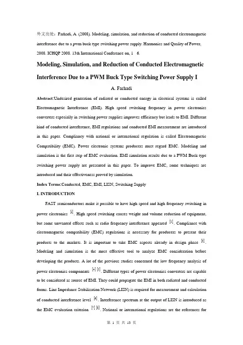
外文出处:Farhadi, A. (2008). Modeling, simulation, and reduction of conducted electromagnetic interference due to a pwm buck type switching power supply. Harmonics and Quality of Power, 2008. ICHQP 2008. 13th International Conference on, 1 - 6.Modeling, Simulation, and Reduction of Conducted Electromagnetic Interference Due to a PWM Buck Type Switching Power Supply IA. FarhadiAbstract:Undesired generation of radiated or conducted energy in electrical systems is called Electromagnetic Interference (EMI). High speed switching frequency in power electronics converters especially in switching power supplies improves efficiency but leads to EMI. Different kind of conducted interference, EMI regulations and conducted EMI measurement are introduced in this paper. Compliancy with national or international regulation is called Electromagnetic Compatibility (EMC). Power electronic systems producers must regard EMC. Modeling and simulation is the first step of EMC evaluation. EMI simulation results due to a PWM Buck type switching power supply are presented in this paper. To improve EMC, some techniques are introduced and their effectiveness proved by simulation.Index Terms:Conducted, EMC, EMI, LISN, Switching SupplyI. INTRODUCTIONFAST semiconductors make it possible to have high speed and high frequency switching in power electronics []1. High speed switching causes weight and volume reduction of equipment, but some unwanted effects such as radio frequency interference appeared []2. Compliance with electromagnetic compatibility (EMC) regulations is necessary for producers to present their products to the markets. It is important to take EMC aspects already in design phase []3. Modeling and simulation is the most effective tool to analyze EMC consideration before developing the products. A lot of the previous studies concerned the low frequency analysis of power electronics components []4[]5. Different types of power electronics converters are capable to be considered as source of EMI. They could propagate the EMI in both radiated and conducted forms. Line Impedance Stabilization Network (LISN) is required for measurement and calculation of conducted interference level []6. Interference spectrum at the output of LISN is introduced as the EMC evaluation criterion []7[]8. National or international regulations are the references forthe evaluation of equipment in point of view of EMC []7[]8.II. SOURCE, PATH AND VICTIM OF EMIUndesired voltage or current is called interference and their cause is called interference source. In this paper a high-speed switching power supply is the source of interference.Interference propagated by radiation in area around of an interference source or by conduction through common cabling or wiring connections. In this study conducted emission is considered only. Equipment such as computers, receivers, amplifiers, industrial controllers, etc that are exposed to interference corruption are called victims. The common connections of elements, source lines and cabling provide paths for conducted noise or interference. Electromagnetic conducted interference has two components as differential mode and common mode []9.A. Differential mode conducted interferenceThis mode is related to the noise that is imposed between different lines of a test circuit by a noise source. Related current path is shown in Fig. 1 []9. The interference source, path impedances, differential mode current and load impedance are also shown in Fig. 1.B. Common mode conducted interferenceCommon mode noise or interference could appear and impose between the lines, cables or connections and common ground. Any leakage current between load and common ground couldbe modeled by interference voltage source.Fig. 2 demonstrates the common mode interference source, common mode currents Iandcm1 and the related current paths[]9.The power electronics converters perform as noise source Icm2between lines of the supply network. In this study differential mode of conducted interference is particularly important and discussion will be continued considering this mode only.III. ELECTROMAGNETIC COMPATIBILITY REGULATIONS Application of electrical equipment especially static power electronic converters in different equipment is increasing more and more. As mentioned before, power electronics converters are considered as an important source of electromagnetic interference and have corrupting effects on the electric networks []2. High level of pollution resulting from various disturbances reduces the quality of power in electric networks. On the other side some residential, commercial and especially medical consumers are so sensitive to power system disturbances including voltage and frequency variations. The best solution to reduce corruption and improve power quality is complying national or international EMC regulations. CISPR, IEC, FCC and VDE are among the most famous organizations from Europe, USA and Germany who are responsible for determining and publishing the most important EMC regulations. IEC and VDE requirement and limitations on conducted emission are shown in Fig. 3 and Fig. 4 []7[]9.For different groups of consumers different classes of regulations could be complied. Class Afor common consumers and class B with more hard limitations for special consumers are separated in Fig. 3 and Fig. 4. Frequency range of limitation is different for IEC and VDE that are 150 kHz up to 30 MHz and 10 kHz up to 30 MHz respectively. Compliance of regulations is evaluated by comparison of measured or calculated conducted interference level in the mentioned frequency range with the stated requirements in regulations. In united European community compliance of regulation is mandatory and products must have certified label to show covering of requirements []8.IV. ELECTROMAGNETIC CONDUCTED INTERFERENCE MEASUREMENTA. Line Impedance Stabilization Network (LISN)1-Providing a low impedance path to transfer power from source to power electronics converter and load.2-Providing a low impedance path from interference source, here power electronics converter, to measurement port.Variation of LISN impedance versus frequency with the mentioned topology is presented inFig. 7. LISN has stabilized impedance in the range of conducted EMI measurement []7.Variation of level of signal at the output of LISN versus frequency is the spectrum of interference. The electromagnetic compatibility of a system can be evaluated by comparison of its interference spectrum with the standard limitations. The level of signal at the output of LISN in frequency range 10 kHz up to 30 MHz or 150 kHz up to 30 MHz is criterion of compatibility and should be under the standard limitations. In practical situations, the LISN output is connected to a spectrum analyzer and interference measurement is carried out. But for modeling and simulation purposes, the LISN output spectrum is calculated using appropriate software.基于压降型PWM开关电源的建模、仿真和减少传导性电磁干扰摘要:电子设备之中杂乱的辐射或者能量叫做电磁干扰(EMI)。
The Application of Visualization Technology in ElectricPower Automation SystemWang Chuanqi, Zou QuanxiElectric Power Automation System Department of Yantai Dongfang Electronics Information IndustryCo., Ltd.Abstract: Isoline chart is widely used chart. The authors have improved the existing isoline formation method, proposed a simple and practical isoline formation method, studied how to fill the isoline chart, brought about a feasible method of filling the isoline chart and discussed the application of isoline chart in electric power automation system.Key words: Visualization; Isoline; Electric power automation systemIn the electric power system industry, the dispatching of electric network becomes increasingly important along with the expansion of electric power system and the increasing demands of people towards electric power. At present, electric network dispatching automation system is relatively advanced and relieves the boring and heavy work for operation staff. However, there is a large amount or even oceans of information. Especially when there is any fault, a large amount of alarm information and fault information will flood in the dispatching center. Faced with massive data, operation staff shall rely on some simple and effective tool to quickly locate the interested part in order to grasp the operation state of the system as soon as possible and to predict, identify and remove fault.Meanwhile, the operation of electric power system needs engineers and analysts in the system to analyze a lot of data. The main challenge that a system with thousands of buses poses for electric power automation system is that it needs to supply a lot of data to users in a proper way and make users master and estimate the state of the system instinctively and quickly. This is the case especially in electric network analyzing software. For example, the displaying way of data is more important in analyzing the relations between the actual trend, planned trend of electric network and the transmission capacity of the system. The application of new computer technology and visualization technology in the electric power automation system can greatly satisfy new development and new demands of electric power automation system.The word “Visualization” originates from English “Visual” and itsoriginal meaning is visual and vivid. In fact, the transformation of any abstract things and processes into graphs and images can be regarded as visualization. But as a subject term, the word “Visualization” officially appeared in a seminar held by National Science Foundation (shortened as NSF) of the USA in February 1987. The official report published after the seminar defined visualization, its covered fields and its recent and long-term research direction, which symbolized that “Visualization” became mature as a subject at the international level.The basic implication of visualization is to apply the principles and methods of computer graphics and general graphics to transforming large amounts of data produced by scientific and engineering computation into graphs and images and displaying them in a visual way. It refers to multi research fields such as computer graphics, image processing, computer vision, computer-aided design (CAD) and graphical user interface (GUI), etc. and has become an important direction for the current research of computer graphics.There are a lot of methods to realize visualization and each method has its unique features and applies to different occasions. Isoline and isosurface is an important method in visualization and can be applied to many occasions. The realization of isoline (isosurface) and its application in the electric power automation system will be explained below in detail.1、 Isoline (Isosurface)Isoline is defined with all such points (x i, y i), in which F(x i, y i)=F i (F i is a set value), and these points connected in certain order form the isoline of F(x,y) whose value is F i…Common isolines such as contour line and isotherm, etc.are based on the measurement of certain height and temperature.Regular isoline drawing usually adopts grid method and the steps are as follows:gridingdiscrete data;converting grid points into numerical value;calculating isoline points; tracing isoline; smoothing and marking isoline; displaying isoline or filling the isoline chart. Recently, some people have brought about the method of introducing triangle grid to solve the problems of quadrilateral grid. What the two methods have in common is to use grid and isoline points on the grid for traveling tracing, which results in the following defects in the drawing process:(1) The two methods use the grid structure, first find out isoline pointson each side of certain quadrilateral grid or triangle grid, and then continue to find out isoline points from all the grids, during which a lot of judgment are involved, increasing the difficulty of program realization. When grid nodes become isoline points, they shall be treated as singular nodes, which not only reduces the graph accuracy but also increases the complexity of drawing.(2) The two methods produce drawn graphs with inadequate accuracy and intersection may appear during traveling tracing. The above methods deal with off-grid points using certain curve-fitting method. That is, the methods make two approximations and produce larger tolerance.(3) The methods are not universal and they can only deal with data of grid structure. If certain data is transformed into the grid structure, interpolation is needed in the process, which will definitely reduce the accuracy of graphs.To solve the problems, we adopt the method of raster graph in drawing isoline when realizing the system function, and it is referred to as non-grid method here. This method needs no grid structures and has the following advantages compared to regular methods:(1) Simple programming and easily realized, with no singular nodes involved and no traveling tracing of isoline. All these advantages greatly reduce the complexity of program design.(2)Higher accuracy. It needs one approximation while regular methods need two or more.(3) More universal and with no limits of grid1.1 Isoline Formation Method of Raster GraphThe drawing of raster graph has the following features: the area of drawing isoline is limited and is composed of non-continuous points. In fact, raster graph is limited by computer screen and what people can see is just a chart formed by thousands of or over ten thousand discrete picture elements. For example, a straight line has limited length on computers and is displayed with lots of discrete points. Due to the limitations of human eyes, it seemscontinuous. Based on the above features, this paper proposes isoline formation method of raster graph. The basic idea of this method is: as computer graphs are composed of discrete points, one just needs to find out all the picture element points on the same isoline, which will definitely form thisisoline.Take the isoline of rectangular mountain area for example to discuss detailed calculation method. Data required in calculation is the coordinates and altitude of each measuring point, i.e., (x i ,y i ,z i ), among which z i represents the altitude of No.i measuring point and there are M measuring points in total. Meanwhile, the height of isoline which is to be drawn is provided. For example, starting from h 0 , an isoline is drawn with every height difference of ∆h0 and total m isolines are drawn. Besides, the size of the screen area to be displayed is known and here (StartX,StartY) represents the top left corner of this area while (EndX ,EndY)represents the low right corner of this area. The calculation method for drawing its isoline is as follows:(1) Find out the value of x i and y i of the top left corner and low right corner points in the drawing area, which are represented by X max ,X min ,Y max ,Y min ;(2)Transform the coordinate (x i ,y i ) into screen coordinate (SX i ,SY i ) and the required transformation formula is as follows:sx i =x i -X min /X max -X min (EndX-StartX)sy i =y i -Y min /Y max -Y min (EndY-StartY)Fig. 1 Height computation sketch(3) i =startX,j=StartY; Suppose i =startX,j=StartY;(4) Use the method of calculating height (such as distance weighting method and least square method, etc.) to calculate out the height h 1, h 2, h 3 of points (i,j), (i+1,j) and (i,j+1), i.e., the height of the three points P 1, P 2 and P 3 in Fig. 1;(5) Check the value of h 1, h 2, h 3 and determine whether there is any isoline crossing according to the following methods:①k=1,h=h 0;①k=1,h=h 0;②Judge whether (P 1-h)*(P 2-h)≤0 is justified. If justified, continue the next step; otherwise, perform ⑤;③Judge whether |P1-h|=|P2-h| is justified. If justified, it indicates that there is an isoline crossing P1, P2, dot the two points and jumpto (6); otherwise, continue next step;④Judge whether |P1-h|<|P2-h|is justified. If justified, it indicates that there is an isoline crossing P1, dot this point; otherwise, dot P2;⑤Judge whether (P1-h)*(P3-h)≤0 is justified. If justified, continue next step; otherwise, perform ⑧.⑥Judge whether|P1-h|=|P3-h|is justified. If justified, dot the twopoints P1\,P3 and jump to (6);otherwise, jump to ⑤;⑦Judge whether|P1-h|<|P3-h|is justified. If justified, dot P1; otherwise, dot P3;⑧Suppose k:=k+1 and judge whether k<m+1 I is justified. If unjustified, continue next step; otherwise, suppose h:=h+∆h0 and return to ②.(6) Suppose j:j+1 and judge whether j<EndY is justified. If unjustified,continue next step; otherwise, return to (4);(7) Suppose i:=i+1 and judge whether i<EndX is justified. If unjustified,continue next step; otherwise, return to (4);(8) The end.In specific program design, in order to avoid repeated calculation, an array can be used to keep all the value of P2 in Column i+1 and another variable is used to keep the value of P3.From the above calculation method, it can be seen th at this method doesn’tinvolve the traveling of isoline, the judgment of grid singular nodes and theconnection of isoline, etc., which greatly simplifies the programming and iseasily realized, producing no intersection lines in the drawn chart.1.2 Griding and Determining NodesTime consumption of a calculation method is of great concern. Whencalculating the height of (i,j), all the contributing points to the height ofthis point need to be found out. If one searches through the whole array, it is very time consuming. Therefore, the following regularized grid method is introduced to accelerate the speed.First, two concepts, i.e., influence domain and influence point set, are provided and defined as follows: Definition 1: influence domain O(P) of node P refers to the largest area in which this nodes has some influence on other nodes. In this paper, it can refer to the closed disc with radius as r (predetermined) or the square with side length as a (predetermined).Definition 2: influence point set S(P)of node P refers to the collection of all the nodes which can influence node P. In this paper, it refers to the point set with the number of elements as n (predetermined), i.e., the number of all the known contributing nodes to the height of node (i,j) can only be n and these nodes are generally n nodes closet to node P.According to the above definition, in order to calculate out the height of any node (i,j), one just needs to find out all the nodes influencing the height of this node and then uses the interpolation method according totwo-dimensional surface fitting. Here, we will explain in detail how to calculate out the height of node (i,j) with Definition 1, i.e., the method of influence domain, and make similar calculation with Definition 2.Grid structure is used to determine other nodes in the influence domainof node (i,j). Irregular area is covered with regular grid, in which the grids have the same size and the side of grid is parallel with X axis and Y axis. The grid is described as follows:(x min,x max,NCX)(y min,y max,NCY)In the formula, x min, y max and x max, y max are respectively the minimum and maximum coordinates of x, y direction of the area; NCX is the number of grids in X direction; NCY is the number of grids in Y direction.Determining which grid a node belongs to is performed in the following two steps. Suppose the coordinate of this node is (x,y). First, respectively calculate its grid No. in x direction and y direction, and the formula is as follows:IX=NCX*(x-x min)/(xmax-x min)+1;IY=NCY(y-y min)/(y max-y min)+1。
The green barrier to free tradeC. P. ChandrasekharJayati GhoshAs the March 31 deadline for completing the "modalities" stage of the proposed new round of negotiations on global agricultural trade nears, hopes of an agreement are increasingly waning. In this edition of Macroscan, C. P. Chandrasekhar and Jayati Ghosh examine the factors and the players constraining the realisation of such an agreement.AT THE END of the latest round of meetings of the agricultural negotiations committee of the WTO, the optimism that negotiators would meet the March 31 deadline for working out numerical targets, formulas and other "modalities" through which countries can frame their liberalisation commitments in a new full-fledged round of trade negotiations has almost disappeared. That target was important for two reasons.First, it is now becoming clear, that even more than was true during the Uruguay Round, forging an agreement in the agricultural area is bound to prove extremely difficult.Progress in the agricultural negotiations was key to persuading the unconvinced that a new `Doha Round' of trade negotiations is useful and feasible.Second, the Doha declaration made agricultural negotiations one part of a `single undertaking' to be completed by January 1, 2005. That is, in a take `all-or-nothing' scheme, countries had to arrive at, and be bound by, agreements in all areas in which negotiations were to be initiated in the new round. This means that if agreement is not worked out with regard to agriculture, there would be no change in the multilateral trade regime governing industry, services or related areas and no progress in new areas, such as competition policy, foreign investment and public procurement, all of which are crucial to the economic agenda of the developed countries.The factors making agriculture the sticking point on this occasion are numerous. As in the last Round, there is little agreement among the developed countries themselves on the appropriate shape of the global agricultural trade regime.There are substantial differences in the agenda of the US, the EU and the developed countries within the Cairns group of agricultural exporters. When the rich and the powerful disagree, a global consensus is not easy to come by.But that is not all. Even if an agreement is stitched up between the rich nations, through manoeuvres such as the Blair House accord, getting the rest of the world to go along would be more difficult this time.This is because the outcomes in the agricultural trade area since the implementation of the Uruguay Round (UR) Agreement on Agriculture (AoA) began have fallen far short of expectations. In the course of Round, advocates of the UR regime had promised global production adjustments that would increase the value of world agricultural trade and an increase in developing country share of such trade.As Chart 1 shows, global production volumes continued to rise after 1994 when the implementation of the Uruguay Round began, with signs of tapering off only in 2000 and 2001. As is widely known, this increase in production occurred in the developed countries as well.Not surprisingly, therefore, the volume of world trade continued to rise as well after 1994 (Chart 2). The real shift occurred in agricultural prices which, after some buoyancy between 1993and 1995, have declined thereafter, and particularly sharply after 1997. It is this decline in unit values that resulted in a situation where the value of world trade stagnated and then declined after 1995, when the implementation of the Uruguay Round began.As Table 1 shows, there was a sharp fall in the rate of growth of global agricultural trade between the second half of the 1980s and the 1990s, with the decline in growth in the 1990s being due to the particularly poor performance during the 1998 to 2001 period.Price declines and stagnation in agricultural trade values in the wake of the UR Agreement on Agriculture were accompanied and partly influenced by the persisting regionalisation of world agricultural trade.The foci of such regionalisation were Western Europe and Asia, with 32 and 11 per cent of global agricultural trade being intra-Western European and intra-Asian trade respectively (Chart 3). What is noteworthy, however, is that agricultural exports accounted for a much higher share of both merchandise and primary products trade in North America and Western Europe (besides Latin America and Africa) than it did for Asia.Thus, despite being the developed regions of the world, agricultural production and exports were important influences on the economic performance of North America and Western Europe.It is, therefore, not surprising that Europe is keen on maintaining its agricultural sector through protection, while the US is keen on expanding its role in world agricultural markets by subsidising its own farmers and forcing other countries to open up their markets. The problem is that the US has been more successful in prising open developing country markets than the large EU market.Thus, out of $104 billion worth of exports from North America in 2001, $34 billion went to Asia and $15 billion to Latin America, whereas exports to Europe amounted to $14 billion.The Cairns group of exporting countries (Argentina, Australia, Bolivia, Brazil, Canada, Chile, Colombia, Costa Rica, Guatemala, Indonesia, Malaysia, New Zealand, Paraguay, the Philippines, South Africa, Thailand and Uruguay), for some of whom at least agricultural exports are extremely important, want world market to be freed of protection as well as the surpluses that result from huge domestic support in the US and the EC.We must note that $35 billion of the $63 billion of exports from Latin America went to the US and the EU. More open markets and less domestic support in those destinations is, therefore, crucial for the region.The fact that Europe has been successful in its effort at retaining its agricultural space with the help of a Common Agricultural Policy that both supports and subsidises its agricultural producers is clear from Chart 4, which shows that intra-EC trade which accounted for 74 per cent of EU exports in 1990, continued to account for 73 per cent of total EU exports in 1995 and 2001.But North America, with far fewer countries in its fold, has also been quite insular. Close to a third of North American exports are inter-regional. Little has changed since the Uruguay Round Agreement on Agriculture.It is widely accepted that three sets of actors account for this failure of the AoA:First, in order to push through an agreement when there were signs that the Uruguay Round was faltering, the liberalisation of agricultural trade in the developed countries was not pushed far enough;Second, is the ability to use "loopholes", especially those in the form of inadequately well-defined Green and Blue Box measures, in the AoA, to continue to support and protect farmers on the grounds that such support was non-trade distorting; andFinally, there are violations of even the lax UR rules in the course of implementation, which have been aided by the failure of the agreement to ensure transparency in implementation.Not surprisingly, some countries, especially the Cairns group of exporting countries, have proposed an ambitious agenda of liberalisation in the agricultural area.Tariffs are to be reduced sharply, using the "Swiss formula", which would ensure that the proportionate reduction in the tariffs imposed by a country would be larger, the higher is the prevailing bound or applied tariff in that country.中文翻译:题目:自由贸易中的绿色壁垒作者:C. P. Chandrasekhar 、Jayati Ghosh在A完自由化的承诺在其最新一轮会议的农业谈判委员会,世界贸易组织,乐观地认为,谈判的框架将在3月31日最后期限为制定数字指标,公式和其他“方式,哪些国家可以”通过新的全面谈判回合贸易几乎已经消失。

外文文献翻译发展中国家需要相互开放市场Developing Countries Need to Open Markets to Each OtherBy David DollarFully half of the benefits to developing countries from stalled multilateral trade negotiations would come from getting better access to each other's markets. They would gain more by lowering their own barriers to agricultural trade than they would by wealthy countries lowering their barriers, although the latter also must happen.With two-thirds of the industrial goods tariffs paid by developing countries going to other developing countries, further trade liberalization could attract foreign investment and advance developing country growth. Completing the Doha Round trade negotiations will require real leadership on the part of the developing world, especially the big developing countries that have benefited so much from globalization.The Doha Round of multilateral trade negotiations is stalled and may very well fall apart. This round of trade liberalization was supposed to be the World Trade Organization's "development round" that would provide benefits in particular to developing countries, which are home to 1 billion people living on less than $1 per day and 2.6 billion living on less than $2. How would a new round of trade liberalization help poor countries?Opening Agricultural MarketsThe most obvious issue—and the one that has received the most attention—is the ongoing agricultural protection of rich countries. Japan protects rice and other markets. The United States and Europe subsidize and protect farmers. Completely liberalizing agricultural markets in rich countries would provide an immediate annual benefit to developing countries of $26 billion, according to a recent World Bank estimate. To put this number in context, it is about one-half of the annual flow of foreign aid from rich countries to poor ones. Thus, opening agricultural markets in rich countries is one important issue.Less well publicized is the fact that opening the agricultural markets of developing countries would provide to these countries a similar—even slightly larger—gain of $28 billion per year. This gain comes partly from the fact that trade liberalization will enable each country to expand production of goods and services that the country makes efficiently and sell them at better prices. Another benefit from trade is that consumers will buy at lower prices goods and services that their country does not produce so well.In addition, developing country liberalization would stimulate South-South trade—trade among developing countries—providing benefits to other poor countries. Where it can beachieved, liberalization of markets for staple foods can particularly help reduce poverty, since these goods account for a large share of expenditure of poor households in developing countries.Cutting Industrial TariffsWhile a lot of attention in trade discussions focuses on the agriculture issue, there is an equally strong case for further liberalizing markets for industrial products. Many developing countries are now efficient producers of manufactured products, especially labor-intensive ones such as textiles and electronics. In fact, 80 percent of the exports of developing countries are manufactured products.The largest markets for industrial goods are in the rich countries, but their import tariffs are already relatively low. Right now, about two-thirds of all industrial tariffs paid by developing-country producers are paid to other developing countries because import tariff rates for industrial products tend to be higher in developing countries.Developing countries thus have a lot to gain from better access to each other's markets. This will enable more efficient firms to expand production and achieve scale economies and will encourage more specialization, as has been seen during European integration over recent decades.The phrase "development round" may suggest to some that the key objective of the current round is to get rich countries to drop their barriers against goods from poor countries. But that move alone would provide only half of the potential benefit that developing countries could gain from a more open trading system. Fully half of the potential benefit to developing countries of trade liberalization comes from better access to each other's markets.Dynamic BenefitsThe benefits that I have discussed so far are what economists call "static benefits"—gains that could come quickly based on current production capabilities. Full trade liberalization would lead to the developed countries reducing production of certain agricultural products, while such production expanded in developing countries having adequate land and water. Developing countries would also expand production and export of labor-intensive manufactures, whereas developed country production would tend to shift into heavy machinery, technology-intensive products, and services. But beyond these static gains, there are also important dynamic benefits. The dynamic effects are hard to quantify, but they are arguably more important than the static gains.What we mean by dynamic benefits is that connecting to a large, global market tends to stimulate innovation and productivity growth at the firm level. Innovation is not just major technological breakthroughs; it is most commonly small changes in the process or products of a firm. Firms in protected markets tend to become complacent, whereas a large competitive market provides a significant outlet for good ideas and high-quality production.The large market also provides for a finer division of labor. A developing country that lowers its own import barriers against manufactured products will typically find that its firms become part of global production networks in which different components and activities that feed into one final product originate in different countries.For developing countries to take part in sophisticated global production networks, they need to have investment climates in which it is relatively easy for firms to start up and expand. They need good transport links to the wider world and efficient customs administration.A final point about the Doha Round is that it is also trying to take up issues of liberalizing trade in services. Many modern services contribute to a good investment climate: finance, insurance, logistics, port management, and transport services, to name a few. Liberalizing imports of these modern services can help developing countries build a stronger investment climate so that their firms can more easily take advantage of global market opportunities.Political Leadership NeededA comprehensive round of trade liberalization will provide benefits to all the countries that are members of the World Trade Organization. If that is true, then why is it so difficult to strike a deal?The well-known political problem with trade liberalization is that a more open market provides diffuse benefits to the whole population, but also imposes large adjustment costs on some specific industries. Of course, the protected farmers in the rich countries lobby against trade liberalization in their sectors. The protected industrial firms and service industries in developing countries likewise lobby. So it takes real political leadership from each country to bring about a deal.It is also both smart and humane to be aware of the losers and to design as much as possible compensation schemes to ease the adjustment. Many countries have adjustment assistance programs to help workers retrain or relocate so that they can take advantage of the opportunities opened up by expanded trade.Previous trade liberalization rounds have appeared close to collapse before an eleventh-hour deal emerged. So for the sake of poor countries, let's hope that political leadership is found all around. A Doha deal will require significant movement on the agricultural protection issue from the United States, Europe, and Japan. But it will also require real leadership on the part of the developing world, especially the big developing countries that have benefited so much from globalization. Further trade liberalization for industrial products and services is very much in the interest of the developing world, but developing country leaders will have to convince their populations of this and find smart ways to help the people who are temporarily hurt during the adjustment.The opinions expressed in this article do not necessarily reflect the views or policies of the U.S. government or of the World Bank and its member countries.发展中国家需要相互开放市场作者David Dollar多边贸易谈判的僵局使发展中国家无法获益,但可能获得的惠益中有一半取决于发展中国家相互改善市场准入。

闽南地区博物馆文物名称英译研究随着全方位对外开放的不断深化,国与国之间的交流更加频繁而密切,更是在无形之中衡量着国家间的综合国力。
伴随着新科技革命的发展,综合国力已不能只讲经济力、政治力、军事力、外交力,更要看文化软实力,而博物馆则是体现国家文化软实力的一大重要标志。
中国五千年的悠久历史沉积出了极其雄厚的历史资源、涵养出了极有底蕴的文化内涵。
而中国珍贵遗产宝库中的文物作为历史文化的一种承载体,其命名不是单纯的给予文物一个称谓的形式,更是要以最精炼的笔触对文物文化特征和历史背景做出较为全面的概括。
在外国游客进行对博物馆的参观时,面对数量庞大的文物展品往往缺少精力进行细致的阅览,于是文物名称英译的重要性就突显而出。
如何以最为简练的文笔、在最短的时间内对读者输出主要信息,使读者正确认识文物、完美捕捉其名称中蕴含的信息,进而更好地弘扬中华名族的悠久历史和灿烂文化,是一个重要的课题,这也意味着对译者的要求有所提高。
闽南地区毗邻海岸,文旅产业兴盛,通常是许多外来旅居者的第一“登岸处”,其博物馆于对外宣传具有一定特殊性。
因此,本文选取闽南地区博物馆为例,对博物馆文物的名称英译进行调查,探究闽南地区博物馆文物名称英译的特点及不足之处。
一、文物名称英译的特点及原则翻译作为一种跨语言、跨文化的交流活动,从表层来看,是将一种语言转化成另一种语言的过程,但从深层来看,其中又包含着不同历史、不同国家与不同文化之间的转化与交流。
而文物名称的翻译又具有特殊性,因文物本身具有鲜明的民族特征和丰富的文化内涵,文物名称是了解一件文物最直观快速的方法,既要简洁明了,又要信息全面,还要重视目的语读者的感受,因此,文物名称英译应遵循交际翻译的原则,贴合简洁性、信息性和通文流畅性的英译特点。
首先,在文物的名称中蕴含着有着文化特色的重要信息需要着重翻译,而有些内容可以加以注释或者忽略不译。
在英汉两种语言有着较大的文化差异的前提下,要求译者能够做出合理的取舍。
乡村文化旅游来自加拿大的案例研究外文文献翻译Tourism has XXX isolated areas。
XXX rural tourism development。
and that culture。
which is often well-preserved in rural areas。
is a valuable resource to include。
nally。
XXX.Keywords: cultural tourism。
rural development。
community-based partnershipnXXX。
such as islands。
XXX industries。
such as fishing and farming。
are in decline。
tourism often es another tool to help create jobs and raise the standards of living。
These areas can realize this potential through the development of local resources。
culture。
and XXX.In fact。
XXX related to the natural environment。
historic heritage。
and cultural patterns。
It is this culture and heritage thatare often well-XXX ds of economic decline。
XXX in many of the small islands of the North Atlantic.Overall。
XXX from the development of local XXX unique culture and heritage。
博物馆的特征名词解释英文Museums are cultural institutions that play a crucial role in preserving, educating, and promoting the world's heritage. They are unique spaces where visitors can explore and learn about the past, present, and future of our society. In this article, we will explore and explain various characteristic terms associated with museums in English, providing a comprehensive understanding of these concepts.1. Collection:A museum's collection refers to its assortment of objects, artworks, artifacts, or specimens carefully curated and preserved for educational and research purposes. Collections may include historic documents, archaeological finds, paintings, sculptures, natural history specimens, and more. Museums often showcase only a fraction of their vast collections, rotating exhibits to provide fresh experiences for visitors and support conservation efforts.2. Curator:Curators are professionals responsible for managing a museum's collections. They undertake tasks such as acquiring new artifacts, conducting research, planning exhibitions, and interpreting objects for public understanding. They possess specialized knowledge in specific fields and collaborate closely with researchers, conservationists, and exhibition designers to curate engaging and informative displays.3. Exhibition:An exhibition is a curated display of objects or artworks organized by museums to educate and entertain visitors. Exhibitions can focus on a particular theme, time period, culture, or artists. They often involve a combination of artifacts, interactive displays, audiovisuals, and informational panels to provide a comprehensive experience. Temporary exhibitions allow museums to present different topics and attract diverse audiences.4. Conservation:Conservation refers to the preservation and restoration of objects in a museum's collection to prevent degradation and ensure their longevity. Conservation professionals use specialized techniques and materials to stabilize and repair artworks or artifacts while maintaining their historical integrity. This field also involves scientific analysis, environmental monitoring, and research to enhance preservation strategies.5. Gallery:A gallery within a museum refers to a designated space or room where artworks or objects are exhibited. Galleries provide sufficient lighting, suitable environmental conditions, and proper display methods to maximize visitor engagement while protecting the objects. Museums often establish galleries based on genre, time periods, or thematic connections to enhance the visitor experience.6. Artifact:An artifact is an object made or modified by human beings in the past that holds cultural, historical, or artistic significance. Artifacts can be tools, pottery, jewelry, clothing, or any item that offers valuable insights into past civilizations. Museums collect and preserve artifacts for their cultural and educational value. They are often accompanied by interpretive labels or multimedia presentations to provide context and enrich visitors' understanding.7. Interactive:Interactive exhibits or installations in museums encourage visitor participation and engagement. These experiences can include touch screens, virtual reality, augmented reality, or physical activities that enable visitors to explore and learn in a hands-on manner. Interactive elements enhance visitor experiences, making museums more accessible and appealing to a wide range of audiences.8. Archaeology:Archaeology is the scientific study of human history through the excavation and analysis of material remains. Archaeological finds, such as tools, pottery, or ancient structures, provide valuable insights into past cultures and help reconstruct our understanding of human civilization. Archaeological museums specialize in displaying and interpreting archaeological artifacts and promoting research in this field.9. Educational Programs:Museums offer educational programs designed for different age groups, such as guided tours, workshops, lectures, or hands-on activities. These programs help deepen visitors' understanding of the exhibits while fostering curiosity and critical thinking skills. Education departments within museums collaborate with schools, universities, and community organizations to develop engaging and relevant programs aligned with curricular goals.10. Outreach:Museum outreach programs aim to connect with communities beyond their physical spaces. They involve collaborations with schools, libraries, community centers, or online platforms to bring museum resources and knowledge to a wider audience. Outreach initiatives can include traveling exhibits, online exhibits, lecture series, or partnerships with other cultural institutions to make museums more accessible and inclusive.In conclusion, museums are vital cultural institutions that embody the collective memory of civilizations. Through their collections, exhibits, and educational programs, they preserve our past, engage the present, and inspire the future. Understanding the characteristic terms associated with museums enhances our appreciation of these institutions and their contributions to society.。
作者简介:陈云萍,翻译硕士。
杜萌萌,通讯作者,副教授。
研究方向:口、笔译理论与实践研究。
收稿日期:2020-7-28(1)2018年8月24日,中国博物馆协会官网公示2014—2016年度国家一级博物馆运行评估结果,在全国96家一级博物馆中,故宫博物院评估结果为优秀;(2)故宫博物院网站的英译采用 “中国本土译者+外国译者”的翻译模式,考虑到了目标语读者的阅读体验,更具研究价值。
因此,本文以故宫博物院英文网站为例,运用交际翻译理论,对博物馆这类外宣文本特有的翻译原则进行探究。
2 文献综述2.1 文物展品解说词翻译原则针对展品解说词翻译,刘庆元(2005)认为,在处理文物翻译这种特殊类别的翻译时,如果“信”与“达”之间存在矛盾,译者应遵守以“达”为先的原则,这样才能达到最佳的译文效果。
杨红英(2012)则提到文物解说词英译应遵从 “读者中心” 的翻译原则。
郦青等(2013)认为丝绸文物解说词英译应遵循“用语专业”“译名统一” “行文简练”和 “读者中心”四原则。
2.2 外宣翻译原则博物馆网站的中译英工作,实质上是一种外宣翻译工作。
黄友义(2004)认为外宣翻译工作应坚持三个原则:贴近中国发展的实际,贴近国外受众对中国信息的需求,贴近国外受众的思维习惯。
仇贤根(2016)认为,外宣翻译人员在工作中应特别遵循四个原则:“内外有别”“外外有别”“含而不露”“以语篇为中心”。
笔者认为,在博物馆网站外宣翻译中,除了基本的外宣翻译原则,博物馆文本特有的翻译原则对译者更具有指导意义。
笔者通过知网检索发现,从交际翻译角度进行博物馆外宣翻译研究的相关文献较少。
因此,笔者从交际翻译理论的视角出发,将博物馆外宣翻译原则归结为目标语读者中心原则、信息突出原则和文化内涵彰显原则。
3 理论依据3.1 交际翻译理论概述纽马克提出,对于属于不同类型文体的原文,译者在翻译中也应采用不同的翻译方法。
在《翻译教程》(A Textbook of Translation )中,纽马克(2001:39)根据文本功能将文本详细分类为:表达型文本、信息型文本、呼唤型文本。
Speech RecognitionVictor Zue, Ron Cole, & Wayne WardMIT Laboratory for Computer Science, Cambridge, Massachusetts, USA Oregon Graduate Institute of Science & Technology, Portland, Oregon, USACarnegie Mellon University, Pittsburgh, Pennsylvania, USA1 Defining the ProblemSpeech recognition is the process of converting an acoustic signal, captured by a microphone or a telephone, to a set of words. The recognized words can be the final results, as for applications such as commands & control, data entry, and document preparation. They can also serve as the input to further linguistic processing in order to achieve speech understanding, a subject covered in section.Speech recognition systems can be characterized by many parameters, some of the more important of which are shown in Figure. An isolated-word speech recognition system requires that the speaker pause briefly between words, whereas a continuous speech recognition system does not. Spontaneous, or extemporaneously generated, speech contains disfluencies, and is much more difficult to recognize than speech read from script. Some systems require speaker enrollment---a user must provide samples of his or her speech before using them, whereas other systems are said to be speaker-independent, in that no enrollment is necessary. Some of the other parameters depend on the specific task. Recognition is generally more difficult when vocabularies are large or have many similar-sounding words. When speech is produced in a sequence of words, language models or artificial grammars are used to restrict the combination of words.The simplest language model can be specified as a finite-state network, where the permissible words following each word are given explicitly. More general language models approximating natural language are specified in terms of a context-sensitive grammar.One popular measure of the difficulty of the task, combining the vocabulary size and the 1 language model, is perplexity, loosely defined as the geometric mean of the number of words that can follow a word after the language model has been applied (see section for a discussion of language modeling in general and perplexity in particular). Finally, there are some external parameters that can affect speech recognition system performance, including the characteristics of the environmental noise and the type and the placement of the microphone.Speech recognition is a difficult problem, largely because of the many sources of variability associated with the signal. First, the acoustic realizations of phonemes, the smallest sound units of which words are composed, are highly dependent on the context in which they appear. These phonetic variabilities are exemplified by the acoustic differences of the phoneme,At word boundaries, contextual variations can be quite dramatic---making gas shortage sound like gash shortage in American English, and devo andare sound like devandare in Italian.Second, acoustic variabilities can result from changes in the environment as well as in the position and characteristics of the transducer. Third, within-speaker variabilities can result from changes in the speaker's physical and emotional state, speaking rate, or voice quality. Finally, differences in sociolinguistic background, dialect, and vocal tract size and shape can contribute to across-speaker variabilities.Figure shows the major components of a typical speech recognition system. The digitized speech signal is first transformed into a set of useful measurements or features at a fixed rate, 2 typically once every 10--20 msec (see sectionsand 11.3 for signal representation and digital signal processing, respectively). These measurements are then used to search for the most likely word candidate, making use of constraints imposed by the acoustic, lexical, and language models. Throughout this process, training data are used to determine the values of the model parameters.Speech recognition systems attempt to model the sources of variability described above in several ways. At the level of signal representation, researchers have developed representations that emphasize perceptually important speaker-independent features of the signal, and de-emphasize speaker-dependent characteristics. At theacoustic phonetic level, speaker variability is typically modeled using statistical techniques applied to large amounts of data. Speaker adaptation algorithms have also been developed that adapt speaker-independent acoustic models to those of the current speaker during system use, (see section). Effects of linguistic context at the acoustic phonetic level are typically handled by training separate models for phonemes in different contexts; this is called context dependent acoustic modeling.Word level variability can be handled by allowing alternate pronunciations of words in representations known as pronunciation networks. Common alternate pronunciations of words, as well as effects of dialect and accent are handled by allowing search algorithms to find alternate paths of phonemes through these networks. Statistical language models, based on estimates of the frequency of occurrence of word sequences, are often used to guide the search through the most probable sequence of words.The dominant recognition paradigm in the past fifteen years is known as hidden Markov models (HMM). An HMM is a doubly stochastic model, in which the generation of the underlying phoneme string and the frame-by-frame, surface acoustic realizations are both represented probabilistically as Markov processes, as discussed in sections,and 11.2. Neural networks have also been used to estimate the frame based scores; these scores are then integrated into HMM-based system architectures, in what has come to be known as hybrid systems, as described in section 11.5.An interesting feature of frame-based HMM systems is that speech segments are identified during the search process, rather than explicitly. An alternate approach is to first identify speech segments, then classify the segments and use the segment scores to recognize words. This approach has produced competitive recognition performance in several tasks.2 State of the ArtComments about the state-of-the-art need to be made in the context of specific applications which reflect the constraints on the task. Moreover, different technologies are sometimes appropriate for different tasks. For example, when the vocabulary issmall, the entire word can be modeled as a single unit. Such an approach is not practical for large vocabularies, where word models must be built up from subword units.The past decade has witnessed significant progress in speech recognition technology. Word error rates continue to drop by a factor of 2 every two years. Substantial progress has been made in the basic technology, leading to the lowering of barriers to speaker independence, continuous speech, and large vocabularies. There are several factors that have contributed to this rapid progress. First, there is the coming of age of the HMM. HMM is powerful in that, with the availability of training data, the parameters of the model can be trained automatically to give optimal performance.Second, much effort has gone into the development of large speech corpora for system development, training, and testing. Some of these corpora are designed for acoustic phonetic research, while others are highly task specific. Nowadays, it is not uncommon to have tens of thousands of sentences available for system training and testing. These corpora permit researchers to quantify the acoustic cues important for phonetic contrasts and to determine parameters of the recognizers in a statistically meaningful way. While many of these corpora (e.g., TIMIT, RM, A TIS, and WSJ; see section 12.3) were originally collected under the sponsorship of the U.S. Defense Advanced Research Projects Agency (ARPA) to spur human language technology development among its contractors, they have nevertheless gained world-wide acceptance (e.g., in Canada, France, Germany, Japan, and the U.K.) as standards on which to evaluate speech recognition.Third, progress has been brought about by the establishment of standards for performance evaluation. Only a decade ago, researchers trained and tested their systems using locally collected data, and had not been very careful in delineating training and testing sets. As a result, it was very difficult to compare performance across systems, and a system's performance typically degraded when it was presented with previously unseen data. The recent availability of a large body of data in the public domain, coupled with the specification of evaluation standards, has resulted inuniform documentation of test results, thus contributing to greater reliability in monitoring progress (corpus development activities and evaluation methodologies are summarized in chapters 12 and 13 respectively).Finally, advances in computer technology have also indirectly influenced our progress. The availability of fast computers with inexpensive mass storage capabilities has enabled researchers to run many large scale experiments in a short amount of time. This means that the elapsed time between an idea and its implementation and evaluation is greatly reduced. In fact, speech recognition systems with reasonable performance can now run in real time using high-end workstations without additional hardware---a feat unimaginable only a few years ago.One of the most popular, and potentially most useful tasks with low perplexity (PP=11) is the recognition of digits. For American English, speaker-independent recognition of digit strings spoken continuously and restricted to telephone bandwidth can achieve an error rate of 0.3% when the string length is known.One of the best known moderate-perplexity tasks is the 1,000-word so-called Resource 5 Management (RM) task, in which inquiries can be made concerning various naval vessels in the Pacific ocean. The best speaker-independent performance on the RM task is less than 4%, using a word-pair language model that constrains the possible words following a given word (PP=60). More recently, researchers have begun to address the issue of recognizing spontaneously generated speech. For example, in the Air Travel Information Service (ATIS) domain, word error rates of less than 3% has been reported for a vocabulary of nearly 2,000 words and a bigram language model with a perplexity of around 15.High perplexity tasks with a vocabulary of thousands of words are intended primarily for the dictation application. After working on isolated-word, speaker-dependent systems for many years, the community has since 1992 moved towards very-large-vocabulary (20,000 words and more), high-perplexity (PP≈200), speaker-independent, continuous speech recognition. The best system in 1994 achieved an error rate of 7.2% on read sentences drawn from North America business news.With the steady improvements in speech recognition performance, systems are now being deployed within telephone and cellular networks in many countries. Within the next few years, speech recognition will be pervasive in telephone networks around the world. There are tremendous forces driving the development of the technology; in many countries, touch tone penetration is low, and voice is the only option for controlling automated services. In voice dialing, for example, users can dial 10--20 telephone numbers by voice (e.g., call home) after having enrolled their voices by saying the words associated with telephone numbers. AT&T, on the other hand, has installed a call routing system using speaker-independent word-spotting technology that can detect a few key phrases (e.g., person to person, calling card) in sentences such as: I want to charge it to my calling card.At present, several very large vocabulary dictation systems are available for document generation. These systems generally require speakers to pause between words. Their performance can be further enhanced if one can apply constraints of the specific domain such as dictating medical reports.Even though much progress is being made, machines are a long way from recognizing conversational speech. Word recognition rates on telephone conversations in the Switchboard corpus are around 50%. It will be many years before unlimited vocabulary, speaker-independent continuous dictation capability is realized.3 Future DirectionsIn 1992, the U.S. National Science Foundation sponsored a workshop to identify the key research challenges in the area of human language technology, and the infrastructure needed to support the work. The key research challenges are summarized in. Research in the following areas for speech recognition were identified:Robustness:In a robust system, performance degrades gracefully (rather than catastrophically) as conditions become more different from those under which it was trained. Differences in channel characteristics and acoustic environment shouldreceive particular attention.Portability:Portability refers to the goal of rapidly designing, developing and deploying systems for new applications. At present, systems tend to suffer significant degradation when moved to a new task. In order to return to peak performance, they must be trained on examples specific to the new task, which is time consuming and expensive.Adaptation:How can systems continuously adapt to changing conditions (new speakers, microphone, task, etc) and improve through use? Such adaptation can occur at many levels in systems, subword models, word pronunciations, language models, etc.Language Modeling:Current systems use statistical language models to help reduce the search space and resolve acoustic ambiguity. As vocabulary size grows and other constraints are relaxed to create more habitable systems, it will be increasingly important to get as much constraint as possible from language models; perhaps incorporating syntactic and semantic constraints that cannot be captured by purely statistical models.Confidence Measures:Most speech recognition systems assign scores to hypotheses for the purpose of rank ordering them. These scores do not provide a good indication of whether a hypothesis is correct or not, just that it is better than the other hypotheses. As we move to tasks that require actions, we need better methods to evaluate the absolute correctness of hypotheses.Out-of-Vocabulary W ords:Systems are designed for use with a particular set of words, but system users may not know exactly which words are in the system vocabulary. This leads to a certain percentage of out-of-vocabulary words in natural conditions. Systems must have some method of detecting such out-of-vocabulary words, or they will end up mapping a word from the vocabulary onto the unknown word, causing an error.Spontaneous Speech:Systems that are deployed for real use must deal with a variety of spontaneous speech phenomena, such as filled pauses, false starts, hesitations, ungrammatical constructions and other common behaviors not found in read speech. Development on the ATIS task has resulted in progress in this area, but much work remains to be done.Prosody:Prosody refers to acoustic structure that extends over several segments or words. Stress, intonation, and rhythm convey important information for word recognition and the user's intentions (e.g., sarcasm, anger). Current systems do not capture prosodic structure. How to integrate prosodic information into the recognition architecture is a critical question that has not yet been answered.Modeling Dynamics:Systems assume a sequence of input frames which are treated as if they were independent. But it is known that perceptual cues for words and phonemes require the integration of features that reflect the movements of the articulators, which are dynamic in nature. How to model dynamics and incorporate this information into recognition systems is an unsolved problem.语音识别舒维都,罗恩科尔,韦恩沃德麻省理工学院计算机科学实验室,剑桥,马萨诸塞州,美国俄勒冈科学与技术学院,波特兰,俄勒冈州,美国卡耐基梅隆大学,匹兹堡,宾夕法尼亚州,美国一定义问题语音识别是指音频信号的转换过程,被电话或麦克风的所捕获的一系列的消息。
第一篇: 航空博物馆与航空展示公园 巴特罗米耶杰·基谢列夫斯基 飞翔的概念、场所的精神、老机场的建筑---克拉科夫新航空博物馆理性地吸取了这些元素,并将它们整合到一座建筑当中。Rakowice-Czyzyny机场之前的旧飞机修理库为新建筑的平面和高度设定了模数比例。在此基本形态上进一步发展,如同裁切和折叠一架纸飞机,生成了一座巨大的建筑。其三角形机翼是由混凝土制成,却如同风动螺旋桨一样轻盈。这个机翼宽大通透,向各个方向开敞。它们的形态与组织都是依据内部功能来设计的。机翼部分为3个不平衡的平面,使内外景观在不断变化中形成空间的延续性,并且联系了建筑内的视觉焦点和室外的展览区。 新航空展示公园的设计连接了博物馆的8栋建筑和户外展览区,并与历史体验建立联系。从前的视觉轴线与通道得到尊重,旧的道路得到了完善 ,朝向飞机场和跑道的空间被限定出来。每栋建筑展示了一个主题或是一段飞行史。建筑周围伸展出巨大的平台,为特殊主题的室外展览提供了空间。博物馆容纳了超过150架飞机、引擎、飞行复制品、成套的技术档案和历史图片。这里的特色收藏是飞机起源开始的各种飞行器,如Jatho1903、Grade1909、莱特兄弟1909年的飞机模 型和1911年的鸽式单翼机。
The first passage: Museum for aviation and aviation exhibition park Bartiomiej Kislelewski The idea of flying, the spirit of place, the structure of the historic airfield – the new Museum of Aviation in Krakow takes up these references intellectually and synthesizes them into a building. The old hangars of the former airport Rakowice Czyzyny set the modular scale for the footprint and the height of the new building. Developed from this basic shape, as if cut out and folded like a paper airplane, a large structure has been generated, with triangular wings made of concrete and yet as light as a wind-vane propeller. The wings are generously glazed and open in all directions. Their form and 毕业设计外文资料翻译 1 arrangement depend on the interior uses. In the floor plans of the wings, the three offset floor layers generate a spatial continuum of varying insights and outlooks, to focal points within the building and to exhibition areas outside. The design of the new aviation park links the eight buildings of the museum and open-air exhibition areas in a joint historical experience. Former view axes and paths are respected, old alleys are completed and spaces towards the airfield and taxiway are defined. Each building exhibits one topic or episode of aviation, with a large base platform extending around it giving spaces for open-air exhibition of the particular themes. The museum contains more than 150 planes, engines, aviation artefacts, sets of technical construction documents and historical pictures. A special feature is the collection of aircraft from the beginning of aviation, such as the Jatho 1903, the Grade 1909, a Wright Brothers model from 1909, and the Etrivh Taube from 1911. 第二篇: 华沙现代艺术博物馆 克里斯蒂安·克雷兹 此建筑正逐步向综合性展览与多功能空间的方向发展。建筑东侧的画廊空间由街道层开始,就在力求营造艺术的可见性与可及性。展厅容纳的功能定位于更广泛的大众----波兰和国际艺术界的“知名人士”将在这里展示他们的作品。 首层空间服务于多种功能----一个大型报告厅和电影院将设置在这里,同时还有一个大型书店、南向观景餐厅、中心广场、以及一个名为“华沙画廊”的附加展示空间----目的是要将当地艺术的气氛、各项目间有趣的互动纳入外界视觉艺术的构架。 博物馆的主要门厅朝向Marszalkowska大街和未来的中心广场,并与博物馆上面各层相连。巨大的、如圆形剧场般的楼梯将参观者引导上来,宽敞的接待大厅将整个楼层分两个部分:巨大的东侧展厅和西侧的画廊。展厅高达16m,具有大教堂般的空间体验,并将容纳大尺度的雕塑类和放置特定的展览项目。 建筑西翼将容纳博物馆的核心部分,即永久展厅,是按照20世纪与21世纪波兰与国际艺术发展史分区设置的展览。附加空间用于对艺术档案与文件的探索与研究。正如开幕展上博物馆临时馆长所说的,“我一睁开眼睛,就会看到一部电毕业设计外文资料翻译 2 影,是那些1960年代、1970年代前南斯拉夫的实验艺术。”在博物馆系列画廊后面是图书馆和阅览室,通过独立的楼梯和街道层入口与首层相连。 通过整合两个楼层的功能、人性化的展览布局、教育区与娱乐区,以及将结构与立面结合的屋顶构件理念,这些措施使该项目达到了最大程度的和谐与统一的效果。
The second passage: Museum of modern art in warsaw Christian Kerez The building is gradually evolving towards the full integration of exhibition and multi-function spaces. The art will be visible- and reachable- from the street level at the gallery space in the east wing of the building .That exhibition hall will host a program aimed at the wide public – “big names” in both Polish and international art will be shown here. The spaces on the ground floor will offer a varied program-both the large auditorium and the cinema hall will be located here, together with a large bookshop, restaurant overlooking the southern, central plaza, and an additional exhibition space, called “The Warsaw Gallery” – aimed at the local artistic milieu, interesting debuts as well interdisciplinary projects, reaching outside the visual arts framework. The main lobby of the Museum will be opened towards both Marszalkowska street and the future central plaza, and it will also connect to the upper floor of the Museum. Wide, amphitheatre-like stairs will lead visitors up, where a roomy reception lobby bisects the whole floor, dividing the vast east exhibition room, reaching 16 meters in height, will give a cathedral-like experience and will host large-scale sculptural and site specific projects. The western wing will house the core of the Museum, i.e. its permanent collection halls, followed by rooms for historical exhibitions of Polish and international art of the 20th and 21st centuries. Additional space will host research projects, aimed at exploration of artistic archives and documentation, such as the inaugural exhibition “As soon as I