转子-轴承-密封系统的多因素动力行为研究
- 格式:pdf
- 大小:509.24 KB
- 文档页数:4
转子动力学转子动力学(Rotordynamics)是一个在机械工程中有着广泛应用的学科,它研究的是转子的运动模式和旋转的动态行为。
它主要包括对转子的结构,刚度,形状,质量及其动态响应的研究,它也可以研究转子系统中出现的振动现象。
转子动力学被广泛应用于一些重要的工程应用,其中,汽轮机,离心机,风力发电机和电机等系统都可以利用转子动力学进行模拟研究,以便于计算转子系统的运动性质和性能。
转子动力学的研究主要分为两个部分:静态和动态分析。
静态分析是指只考虑转子的静力学性质,即转子的位移,速度和加速度,而不考虑其在轴承振动中的动态特性。
动态分析则是指考虑转子在轴承振动中的动态特性,包括振动模式、振动频率、振动幅值及衰减。
转子动力学的静态分析方法很多,其中,应用频繁的有建立结构方程和有限元方法,它们分别用于研究转子结构的位移,形变和应力分布,及轴承摩擦耦合下转子的动态行为。
动态分析方法也有很多,例如建立模态方程和复结构动力学方法等,它们都有助于研究转子系统的动态行为,包括振动模式、振动频率、振动的位移、形变和应力分布。
转子动力学的应用非常广泛,它可以被用于传动系统,机床,风机,汽轮机,离心机,风力发电机等系统中,以改善其设计和性能。
由于转子动力学完备及计算量大,现代转子断面设计工具和分析工具均已经发展趋于成熟,可以实现转子的3D的模拟分析,并可以实现转子的断面设计改善。
转子动力学是实施转子系统设计,并实现转子系统性能改善的重要手段,它给转子系统提供了科学的基础,使得转子系统设计及性能改善更接近设计者的实际需求,从而达到节省成本,提高效率,提升产品性能的目的。
总之,转子动力学研究是机械工程中一个重要的学科,它在机械系统安全可靠运行方面发挥着非常重要的作用。
通过使用转子动力学,可以更好地分析和理解转子系统的结构,刚度,形状,质量及其动态响应,从而实现设计的优化,提高转子系统的性能,改善转子系统的安全可靠性。
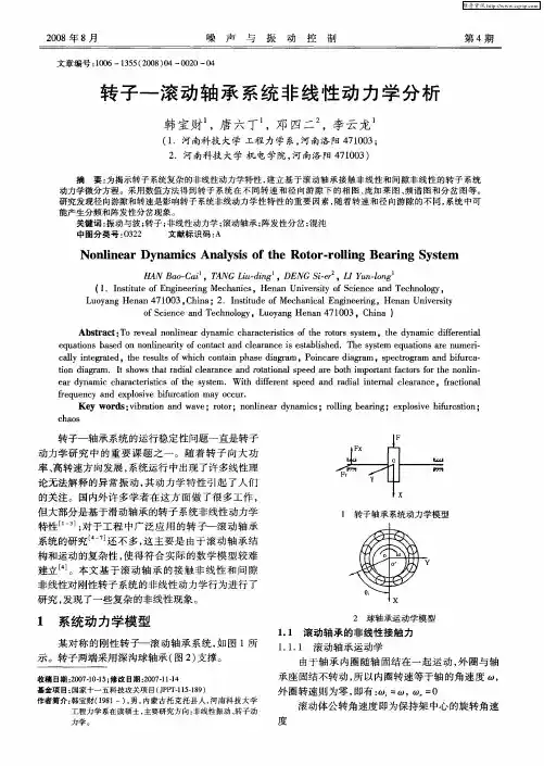
附录A英文原文Experimental and Numerica Studies on Nonlinear Dynam Behavior of Rotor System Supported by Ball BearingsBall bearings are important mechanical components in high-speed turbomachinery that is liable for severe vibration and noise due to the inherent nonlinearity of ball ing experiments and the numerical approach, the nonlinear dynamic behavior of a flexible rotor supported by ball bearings is investigated in this paper. An experimental ball bearing-rotor test rig is presented in order to investigate the nonlinear dynamic performance of the rotor systems, as the speed is beyond the first synchroresonance frequency. The finite element method and two-degree-of-freedom dynamic model of a ball bearing are employed for modeling the flexible rotor s ystem. The discrete model of a shaft is built with the aid of the finite element technique, and the ball bearing model includes the nonlinear effects of the Hertzian contact force, bearing internal clearance, and so on.The nonlinear unbalance response is observed by experimental and numerical analysis.All of the predicted results are in good agreement with experimental data, thus validating the proposed model. Numerical and experimental results show that the resonance frequency is provoked when the speed is about twice the synchroresonance frequency, while the subharmonic resonance occurs due to the nonlinearity of ball bearings and causes severe vibration and strong noise. The results show that the effect of a ball bearing on the dynamic behavior is noticeable in optimum design and failure diagnosis of high-speed turbomachinery. [DOI: 10.1115/1.4000586]Keywords: ball bearing, rotor, experiment, nonlinear vibrationA.1 IntroductionBall bearings are one of the essential and important components in sophisticated turbomachinery such as rocket turbopumps, aircraft jet engines, and so on. Because of the requirement of acquiring higher performance in the design and operation of ballbearings-rotor systems, accurate predictions of vibration characteristics of the systems, especially in the high rotational speed condition, have become increasingly important.Inherent nonlinearity of ball bearings is due to Hertzian contact forces and the internal clearance between the ball and the ring.Many researchers have devoted themselves to investigating the dynamiccharacteristics associated with ball bearings. Gustafsson et al. [1] studied the vibrations due to the varying compliance of ball bearings. Saito [2] investigated the effect of radial clearance in an unbalanced Jeffcott rotor supported by ball bearings using the numerical harmonic balance technique. Aktürk et al. [2] used a three-degree-of-freedom system to explore the radial and axial vibrations of a rigid shaft supported by a pair of angular contact ball bearings. Liew et al. [4] summarized four different dynamic models of ball bearings, viz., two or five degrees of freedom, with or without ball centrifugal force, which could be applied to determine the vibration response of ball bearing-rotor systems. Bai and Xu [5] presented a general dynamic model to predict dynamic properties of rotor systems supported by ball bearings. De Mul et al. [6] presented a five-degree-of-freedom (5DOF) model for the calculation of the equilibrium and associated load distribution in ball bearings. Mevel and Guyader [7] described different routes to chaos by varying a control parameter. Jang and Jeong [8] proposed an excitation model of ball bearing waviness to investigate the bearing vibration. Then, considering the centrifugal force and gyroscopic moment of ball, they developed an analytical method to calculate the characteristics of the ball bearing under the effect of waviness in Ref. [9]. Tiwari et al. [10,11] employed a two-degree-of-freedom model to analyze the nonlinear behaviors and stability associated with the internal clearance of a ball bearing.Harsha [12-14], taking into account different sources of nonlin-earity, investigated the nonlinear dynamic behavior of ball bearing-rotor systems. Gupta et al. [15] studied the nonlinear dynamic response of an unbalanced horizontal flexible rotor supported by a ball bearing. With the aid of the Floquet theory, Bai et al. [16] investigated the effects of axial preload on nonlinear dynamic characteristics of a flexible rotor supported by angular contact ball bearings. Using the harmonic balance method, Sinou [17]performed a numerical analysis to investigate the nonlinear unbalance response of a flexible rotor supported by ball bearings.In the abovementioned studies, main attention has been paid to the ball bearing modeling and the dynamic properties analysis according to simple bearing-rotor models. With theoretical analysis and experiment, Yamamoto et al. [18] studied a nonlinear forced oscillation at a major critical speed in a rotating shaft,which was supported by ball bearings with angular clearances.Ishida and Yamamoto [19] studied the forced oscillations of a rotating shaft with nonlinear spring characteristics and internal damping. They found that a self-excited oscillation appears in the wide range above the major critical speed. A dynamic model was derived, and experiments are carried out with a laboratory test rig for studying the misaligned effect of misaligned rotor-ball bearing systems in Ref. [20]. Tiwari et al. [21] presented an experimental analysis to study the effect of radial internal clearance of a ball bearing on the bearingstiffness of a rigid horizontal rotor. These experimental results validated theoretical results reported in their literatures [10,11]. Recently, Ishida et al. [22] investigated theoretically and experimentally the nonlinear forced vibrations and parametrically excited vibrations of an asymmetrical shaft supported by ball bearings. Mevel and Guyader [23] used an experimental test bench to confirm the predicted routes to chaos in their previous paper [7]. It is noticeable of lack of experiments on nonlinear dynamic behavior of flexible rotor systems supported by ball bearings. In Ref. [24], the finite element method was used to model a LH2 turbopump rotor system supported by ball bearings. Numerical results show that the subharmonic resonance, as well as synchroresonance, occurs in the start-up process. It is found that the subharmonic resonance is an important dynamic behavior and should be considered in engineering ball bearing-rotor system design. But, the experimental and numerical studies of the subharmonic resonance in ball bearing-rotor systems are very rare.With respect to the above, the present study is intended to cast light on the subharmonic resonance characteristics in ball bearing-rotor systems using experiments and numerical approach. An experiment on an offset-disk rotor supported by ball bearings is carried out, and the finite element method and two-degree-of-freedom model of a ball bearing are employed for modeling this rotor system. The predicted results are compared with the test data, and an investigation is conducted in the nonlinear dynamic behavior of the ball bearings-rotor system.2 Experimental InvestigationAn experimental rig is employed for studying the nonlinear dynamic behavior of ball bearing-rotor systems, as shown in Fig.1. The horizontal shaft is supported by two ball bearings at both ends, and the diskis mounted unsymmetrically. The shaft is coupled to a motor with a flexible coupling. The motor speed is controlled with a feedback controller, which gets the signals from an eddy current probe. Four eddy current probes, whose resolution is 0.5 m, are mounted close to the disk and bearing at the right end in the horizontal and vertical directions, respectively. The displacement signals, obtained with the help of probes, are input into an oscilloscope to describe the motion orbit, and a data acquisition and processing system were used to analyze the effects of ball bearings on the nonlinear dynamic behavior. The data acquisition and processing system utilizes a full period sampling as the data acquisition method. Its sampling rate is 500 kHz maximum, and sample size is 12 bits. The system provides eight channels for vibratory response acquisition and 1 channel for rotational speed acquisition. All channels are simultaneous.The limitation with the presented experimental setup is that the maximum attainable speed is 12,000 rpm. The first critical speed of the rotor system falls in the speed span, as the shaft is flexible and its fist synchroresonance frequency is near 66 Hz (3960rpm).Thus, the dynamic behavior can be studied as the speed is beyond twice the synchroresonance frequency.3 Rotor Dynamic ModelThe bearing-rotor system combines an offset-disk and two ball bearings, which support the rotor at both ends. The sketch map of the system is described in Fig. 2, where the frame oxyz is the inertial frame. The corresponding experiment assembly is shown in Fig. 3.3.1 Equations of Motion . Define ux and uy as the transverse deflections along the ox and oy directions, and x θ and y θ as the corresponding bending angles in the oxz and oyz planes, respectively. When x u 1, y u 1,x 1θ , and y 1θ denote the displacements of the ball bearing center location at the left end, the complex variables 1u and 1θ can be assumed asDenote the displacements of the disk center by 2u and 2θ, and the displacements of the ball bearing center location at the right end by 3u and 3θ. Using the finite element method, the equations of motion for the rotor system can be written as [25,26]where []M , []C , []K , and []G are the mass, damping, stiffness, and gyroscopic matrix of the rotor system, respectively, ω is the rotational speed, and {}u is the displacement vector{}g F and {}u F are the vectors of gravity load and unbalance forces.{}bF is the vector of nonlinear forces associated with ball bearings.3.2 Ball Bearing Forces. A ball bearing is depicted in a frame of axes oxyz in Fig.4. The contact deformation for the j-th rolling element j δis given aswhere i c and o c are the internal radial clearance between the inner,outer race, and rolling elements, respectively, in the direction of contact, and ubx and uby are the relative displacements of the inner and outer race along the x and y directions, respectively. As shown in Fig. 4, the angular location of the j-th rolling element j ϕ can be obtained fromWhere N , c ω, t , and 0ϕ are the number of rolling elements, cage angular velocity, time, and initial angular location, respectively. The cage angular velocity can be expressed as [27]where b D and p D are the ball diameter and bearing pitch diam- eter,respectively. α is the contact angle, which is concerned with the clearance and can be obtained as follows:Referring to Fig. 4, i r and o r are the inner and outer groove radius,respectively.If the contact deformation j δ is positive, the contact force could be calculated using the Hertzian contact theory; otherwise, no load is transmitted. The contact force j Q between the j-th ball and race can be expressed as follows:where b k is the contact stiffness that can be given bywhere bi k and bo k are the load-deflection constants between the inner and outer ball race, respectively[28]. Summing the contact forces for each rolling element, the total bearing reaction fb in a complex form is4 Experimental and Numerical AnalysisAs shown in Fig. 2, the experimental assembly and the finite element model used in the dynamic analysis represent the ball bearing-rotor system with the following geometrical properties:length between the disk center and left end bearing center mm L 1201=; length between the disk center and right end bearing center mm L 1202=; and the shaft diameter mm D 10=. In addition, the elastic shaft material is steel of density 37950m kg =ρ,Young’s modulus GPa E 211=, and Poisson’s ratio 3.0=v . The ball bearings at both ends are the same model, 7200AC, and its parameters are listed in Table 1.The unbalance load is acted wit h the aid of the mass fixed on the disk. By virtue of this act, the mass eccentricity of the disk can be definitely ascertained. As the mass eccentricity of the disk is 0.032 mm, the vibratory response at different rotational speed is determined via a numerical integration and Newton –Raphson iterations of the nonlinear differential equation (2). Note that the clearances used to simulate the bearings are measured ones. The horizontal and vertical displacements signals near the disk are acquired at different times, along with the increased rotational speed. Thus, the amplitudes of vibration at different speeds are determined according to the test data, and overall amplitudes are illustrated in Fig. 5, as the rotor system is run from 2000=ω rpm to 10,000 rpm. The prediction results compared with experimental data are shown in Fig. 5. It can be found that all of the predicted results are in good agreement with experimental data, thus validating the proposed model. The first predicted resonance peak—the so called forward critical speed in linear theory,located at3960=ω rpm, matches the experimental date near 3960=ω rpm quite well. Moreover, the other amplitude peak appearing in the rotational speedrange7700=ω rpm to 8100 rpm can be found in both experimental and numerical analysis results.The corresponding frequency value of this peak is just the frequency doubling of the system critical speed.The Floquet theory can be used for analyzing the stability and topological properties of the periodic solution of the ball bearingrotor system. If the gained Floquet multipliers are less than unity,the periodic solution of the system is stable. If at least one Floquet multiplier exists with the absolute value higher than unity, the periodic solution is unstable and the topological properties of response alter into nonperiodic motion [29]. The leading Floquet multipliers and its absolute value at 7600=ω rpm, 8029 rpm, and 8200 rpm are shown in Table 2. It is found that the leading Floquet multiplier of the system remains in the unit circle, which indicates a synchronous response, as the rotational speed is less than 7700 rpm. Stability analysis shows that the imaginary part of the two leading Floquet multipliers move in opposite directions along the real axis near 7700=ω rpm. When the speed exceeded 7700=ω rpm, the leading Floquet multiplier crosses the unit circle through -1, as shown in Table 2. The periodic solution loses stability and undergoes a period-doubling bifurcation to a period-2 response, which indicates that a subharmonicresonance occurs. The subharmonic resonance keeps on from 7700=ω rpm to 8100 rpm. At 8100=ω rpm, the leading Floquet multiplier moves inside the unit circle through -1. Imply that the subharmonic resonance vanishes and the synchronous response returns. The synchronous response then continues to exist forspeeds above 8100=ω rpm.The waterfall map of frequency spectrums comparisons for prediction and experiment results are illustrated in Fig. 6. It can be found that agreement between the prediction and the experimental data is remarkable. The frequency component 66.9 Hz, near the forward resonance frequency, emerges and its amplitude rises significant when the rotational speed is near 8029 rpm. It is shown that the resonance frequency is provoked when the speed is about twice the critical speed of the ball bearing-rotor system, and the subharmonic resonance occurs. The experimental and numerical analysis indicate that the representative nonlinear behavior and the subharmonic resonance arise from the nonlinearity of ball bearings, Hertzian contact forces, and internal clearance.The orbit and frequency spectrum at 8029=ω rpm are plotted in Fig. 7. Not only the prediction orbit but also the experiment results imply that the response is a period-2 motion, which is illustrated in Fig. 7(a). The predicted frequency components, consisting of 8.133=ω Hz (8029 rpm) and 9.662=ω Hz (4014rpm), coincide with experimental data. It indicates that the periodic response loses stability through a period-doubling bifurcation to a period-2 response. Thus, the subharmonic resonance occurs due to the effects of ball bearings. It can cause severe vibration and strong noise. Moreover, the subharmonic resonance could couple with other destabilizing effects on engineering rotor systems such as Alford forces, internal damping, and so on, and induce the rotor to lose stability and damage.5 ConclusionsAn experimental rig is employed to investigate the nonlinear dynamic behavior of ball bearing-rotor systems. The corresponding dynamic model is established wi th the finite element method and 2DOF dynamic model of a ball bearing, which includes the nonlinear effects of the Hertzian contact force and bearing internal clearance. All of the predicted results are in good agreement with experimental data, thus validating the proposed model. Numerical and experimental results show that the resonance frequency is provoked, and the subharmonic resonance occurs due to the nonlinearity of ball bearings when the speed is about twice the synchroresonance frequency. The subharmonic resonance cannot only cause severe vibration and strong noise, but also induce the rotor to lose stability and damage, once coupled with other destabilizing effects on high-speed turbomachinery such as Alford forces, internal damping, and so on. It is found that the effect of the Hertzian contact forces could also induce a subharmonic resonance, even if the internal clearance was not present. But, the response amplitude and subharmonic component of the rotor system without internal clearance are less than that with both Hertzian contact forces and internal clearance. Otherwise, the clearance may be unavoidable under high-speed operations, where the bearings are axially preloaded since the effect of unbalanced load is significant at high speed. Thus, the nonlinearity of ball bearings,Hertzian contact forces, and internal clearance should be taken into account in ball bearing-rotor system design and failure diagnosis.AcknowledgmentThe authors would like to acknowledgment the support of the National Natural Science Foundation of China (Grant No.10902080) and Natural Science Foundation of Shaanxi Province(Grant Nos. SJ08A19 and 2009JQ1008).References[1] Gutafsson, O., and Tallian, T., 1963, “Resear ch Report on Study of the Vibration Characteristics of Bearings,” SKF Ind. Inc. Technical Report No.AL631023.[2] Saito, S., 1985, “Calculation of Non-Linear Unbalance Response of Horizontal Jeffcott Rotors Supported by Ball Bearings With Radial Clearances,” ASME J.Vib., Acou st., Stress, Reliab. Des., 107(4), pp. 416–420.[3] Aktürk, N., Uneeb, M., and Gohar, R., 1997, “The Effects of Number of Balls and Preload on Vibrations Associated With Ball Bearings,” ASME J. Tribol.,119, pp. 747–753.[4] Liew, A., Feng, N., and Hahn, E., 2002, “Transient Rotordynamic Modeling of Rolling Element Bearing Systems,” ASME J. Eng. Gas Turbines Power,124(4), pp. 984–991.[5] Bai, C. Q., and Xu, Q. Y., 2006, “Dynamic Model of Ball Bearing With Internal Clearance and Waviness,” J. Sound Vib., 294(1-2), pp. 23–48.[6] De Mul, J. M., Vree, J. M., and Maas, D. A., 1989, “Equilibrium and Associated Load Distribution in Ball and Roller Bearings Loaded in Five Degrees of Freedom While Neglecting Friction—Part I: General Theory and Application to Ball Be arings,” ASME J. Tribol., 111, pp. 142–148.[7] Mevel, B., and Guyader, J. L., 1993, “Routes to Chaos in Ball Bearings,” J.Sound Vib., 162, pp. 471–487.[8] Jang, G. H., and Jeong, S. W., 2002, “Nonlinear Excitation Model of Ball Bearing Waviness in a Rigid Rotor Supported by Two or More Ball Bearings Considering Five Degrees of Freedom,” ASME J. Tribol., 124, pp. 82–90.[9] Jang, G. H., and Jeong, S. W., 2003, “Analysis of a Ball Bearing With Waviness Considering the Centrifugal Force and Gyroscopic Moment of the Ball,”ASME J. Tribol., 125, pp. 487–498.[10] Tiwari, M., Gupta, K., and Prakash, O., 2000, “Effect of Radial Internal Clearance of a Ball Bearing on the Dynamics of a Balanced Horizontal Rotor,” J.Sound Vib., 238(5), pp. 723–756.[11] Tiwari, M., Gupta, K., and Prakash, O., 2000, “Dynamic Response of an Unbalanced Rotor Supported on Ball Bearings,” J. Sound Vib., 238(5), pp.757–779.[12] Harsha, S. P., 2005, “Non-Linear Dynamic Response of a Balanced Rotor Supported on Rolling Element Bearings,” Me ch. Syst. Signal Process., 19(3),pp. 551–578.[13] Harsha, S. P., 2006, “Rolling Bearing Vibrations—The Effects of Surface Waviness and Radial Internal Clearance,” Int. J. Computational Methods in Eng Sci. and Mech., 7(2), pp. 91–111.[14] Harsha, S. P., 2006, “Nonlinear Dynamic Analysis of a High-Speed Rotor Supported by Rolling Element Bearings,” J. Sound Vib., 290(1–2), pp. 65–100.[15] Gupta, T. C., Gupta, K., and Sehqal, D. K., 2008, “Nonlinear Vibration Analysis of an Unbalanced Flexible Rotor Supported by Ball Bearings With Radial Internal Clearance,” Proceedings of the ASME Turbo Expo, Vol. 5, pp. 1289–1298.[16] Bai, C. Q., Zhang, H. Y., and Xu, Q. Y., 2008, “Effects of Axial Preload of Ball Bearing on theNonlinear Dynamic Characteristics of a Rotor-Bearing System,” Nonlinear Dyn., 53(3), pp. 173–190. [17] Sinou, J. J., 2009, “Non-Linear Dynamics and Contacts of an Unbalanced Flexible Rotor Supported on Ball Bearings,” Mech. Mach. Theory, 44(9), pp.1713–1732.[18] Yamamoto, T., Ishida, Y., and Ikeda, T., 1984, “Vibrations of a Rotating Shaft With Rotating Nonlinear Restoring Forces at the Major Critical Speed,” Bull.JSME, 27(230), pp. 1728–1736.[19] Ishida, Y., and Yamamoto, T., 1993, “Forced Oscillations of a Rotating Shaft With Nonlinear Spring Characteristics and Internal Damping (1/2 Order Subharmonic Oscillations and Entrainment),” Nonlinear Dyn., 4(5), pp. 413–431.[20] Lee, Y. S., and Lee, C. W., 1999, “Modeling and Vibration Analysis of Misaligned Rotor-Ball Bearing Systems,” J. Sound Vib., 224(1), pp. 17–32.[21] Tiwari, M., Gupta, K., and Prakash, O., 2002, “Experimental Study of a Rotor Supported by Deep Groove Ball Bearing,” Int. J. Rotating Mach., 8(4), pp.243–258.[22] Ishida, Y., Liu, J., Inoue, T., and Suzuki, A., 2008, “Vibrations of an Asymmetrical Shaft With Gravity and Nonlinear Spring Characteristics (IsolatedResonances and Internal Resonances),” ASME J. Vib. Acoust., 130(4),p.041004.[23] Mevel, B., and Guyader, J. L., 2008, “Experiments on Routes to Chaos in Ball Bearings,” J. S ound Vib., 318, pp. 549–564.[24] Bai, C. Q., Xu, Q. Y., and Zhang, X. L., 2006, “Dynamic Properties Analysis of Ball Bearings—Liquid Hydrogen Turbopump Used in Rocket Engine,”ACTA Aeronaut. Astronaut. Sinica, 27(2), pp. 258–261. [25] Nelson, H., 1980, “A Finite Rotating Shaft Element Using Timoshenko Beam Theory,” ASME J. Mech. Des., 102(4), pp. 793–803.[26] Zhang, W., 1999, Basis of Rotordynamic Theory, Science Press, Beijing,China, Chap. 3.[27] Harris, T. A., 1984, Rolling Bearing Analysis, 2nd ed., Wiley, New York.[28] Aktürk, N., 1993, “Dynamics of a Rigid Shaft Supported by Angular Contact Ball Bearings,” Ph.D. thesis, Imperial College of Science, Technology and Medicine, London, UK.[29] Zhou, J. Q., and Zhu, Y. Y., 1998, Nonlinear Vibrations, Xi’an Jioatong University Press, Xi’an, China.附录B英文翻译非线性动力学的实验和转子轴承系统支持的行为的数值研究深沟球轴承在高速流体机械部件承担严重的振动和噪声的固有的非线性是很重要的。
对挤压油膜阻尼器轴承和旋转机械转子—挤压油膜阻尼器轴承系统动力特性研究的回顾与展望ΞRETROSPECT AN D PROSPECT TO THE RESEARCH ON SQUEEZE FI LM DAMPER BEARING (SFDB)AN D ON DY NAMIC CHARACTERISTICSOF ROTATING MACHINER Y ROTOR —SFDB SYSTEM夏 南ΞΞ1 孟 光1,2(1.上海交通大学振动、冲击、噪声国家重点实验室,上海200030) (2.佛山大学思源研究所,佛山528000)XI A Nan 1 MEN G Guang 1,2(1.State K ey Laboratory o f Vibration ,Shock and Noise ,Shanghai Jiaotong Univer sity ,Shanghai 200030,China )(2.Siyuan Institute ,Foshan Univer sity ,Foshan 528000,China )摘要 简要介绍挤压油膜阻尼器轴承及其基本分类,介绍各种挤压油膜阻尼器轴承的动力学特性研究和建立阻尼器流体动力模型与挤压油膜力的进展情况,总结了支承在挤压油膜阻尼器轴承上的旋转机械转子系统的动态响应特性和稳定性的研究结果及对这类强非线性的转子—阻尼器支承系统的非线性响应特性研究的进展情况,并对该类减振结构的未来发展进行了展望。
关键词 转子动力学 挤压油膜阻尼器轴承 油膜惯性力 回顾与展望中图分类号 TH113 T B535.1 O328Abstract Squeeze film dam per bearing (SFDB )is now widely used in aeroengine and other rotating machineries due to its advantages of obvious is olating effect ,sim ple structure ,small space and easy manu facturing.In this paper ,different kinds of SFDB and the research results on the dynamic characteristics of these SFDB and on the m odels of fluid dynamic and squeeze film force were introduced.The research achievements on the dynamic response characteristics and stability of the rotating machinery rotor supported on SFDB were reviewed.Als o the progressing on the nonlinear responses analysis of such strong nonlinear rotor —dam per support system was introduced.The future development of and research on the SFDB was prospected.K ey w ords R otordynamics;Squeeze film d amper bearing;F luid inertia force ;R etrospect and prospect Correspondent :MENG Guang ,E 2mail :gmeng @mail ,Fax :+862212629322212804The project supported by the National Defense Pre 2Research Project and the University K ey T eacher Support Program of China.Manuscript received 20010128,in revised form 20010412.1 引言自从第一篇有关转子动力学的论文由Rankine [1]发表以来,转子动力学作为动力学的一个独立分支得到了极大的发展。
航空发动机滚动轴承及其双转子系统共振问题研究综述作者:李轩来源:《科技风》2022年第11期摘要:针对航空燃气涡轮发动机滚动轴承及其双转子系统存在的复杂振动问题,综述了近年来国内外该领域的主要研究成果。
首先,概述了双转子系统动力学建模与分析的研究成果。
其次,综述了双转子系统动力学响应分析研究的现状与主要进展。
最后对现有研究工作进行了展望,对该领域的发展趋势进行了说明。
关键词:转子动力学;双转子系统;共振;非线性;滚动轴承滚动轴承及其双转子系统作为航空燃气涡轮发动机的主要结构,存在着大量复杂振动现象,能够引发系统复杂故障甚至灾难性的事故,其产生机理十分复杂。
所以人们针对相关系统进行了大量研究,从不同角度研究并阐述了多种复杂共振现象的触发机制,对进一步改善航空燃气涡轮发动机等相关滚动轴承—双转子系统机械的安全性、稳定性、可靠性具有重要的理论与实际工程意义。
为了缓解航空燃气涡轮发动机滚动轴承及其双转子系统运行时的高频小幅度不规则运动,防止系统在特定运行条件下产生有害共振,并仍能保持良好的动力学性能。
学者们需要深入研究航空发动机滚动轴承—双转子系统的运动学与造成其运动的力学特点,从而分析解决实际系统存在的各种共振问题。
为此,研究创建适合于剖析滚动轴承—双转子系统动力学特性的模型很有必要。
本文对航空发动机滚动轴承—双转子系统动力学建模以及双转子系统的动力学响应特性的研究现状进行了归纳,并对滚动轴承及其双转子系统共振研究的发展趋势进行了预测。
1 航空发动机双转子系统的动力学建模与分析实际双转子航空燃气涡轮发动机工况十分复杂,为了准确研究航空燃气涡轮发动机滚动轴承—双转子系统运行中的动力学行为,航空燃气涡轮发动机双转子系统的动力学建模问题被学者们广泛研究。
路振勇等[1]依据某真实航空发动机的双转子系统,创建了较为复杂的非连续化动力学模型。
并在对该模型进行了降维后,计算了系统发生共振的对应转速,发现依据复杂非连续化动力学模型计算得到的结果与采用传统方法计算得到的结果相比差异极小,证明了降维模型能很好反映双转子系统的实际共振特性。
磁悬浮轴承稳定性分析磁悬浮轴承(Magnetic Bearing)是利用磁力作用将转子悬浮于空中,使转子与定子之间没有机械接触。
与传统的滚珠轴承,滑动轴承以及油膜轴承相比,磁轴承不存在机械接触,转子的转速可以运行到很高,具有机械磨损小,能耗低,噪声小、寿命长、无需润滑,无油污染等优点,特别适用于高速、真空、超净等特殊环境。
这项技术是20世纪60年代中期在国际上开始研究的一项新的支撑技术。
在各个领域都有着广泛的应用。
本文主要分析磁悬浮轴承的稳定性问题。
文章的第一部分介绍了磁悬浮轴承在国际和国内的发展与研究现状,并分析了磁悬浮轴承的一些特点。
文章的第二部分对磁悬浮轴承的稳定性进行了讨论,先论证了永磁轴承无法实现自稳定,然后对电磁轴承的稳定性进行了分析。
关键词:磁悬浮,轴承,电磁轴承,永磁轴承,稳定性第一章引言第一节磁悬浮轴承的研究背景国际上很早就有了利用磁力使物体处于无接触悬浮状态的设想, 但其实现却经历了很长的一段时间。
1842 年, Earnshow 证明: 单靠永磁体不能将一个铁磁体在所有 6 个自由度上都保持在自由稳定的悬浮状态.真正意义上的磁悬浮研究开始于20世纪初的利用电磁相吸原理的悬浮车辆研究,1937 年, Kenper 申请了第一个磁悬浮技术专利, 他认为,要使铁磁体实现稳定的磁悬浮, 必须根据物体的悬浮状态不断的调节磁场力的大小,因此必须采用可控电磁铁,这也是以后开展磁悬浮列车和磁悬浮轴承研究的主导思想。
随着现代控制理论和电子技术的飞跃发展, 20世纪 60 年代中期对磁悬浮技术的研究跃上了一个新台阶。
日本、英国、德国都相继开展了对磁悬浮列车的研究。
资料记载: 1969 年, 法国军部科研实验室(LRBA ) 开始对磁悬浮轴承的研究; 1972 年,第一个磁悬浮轴承用于卫星导向轮的支撑上, 从而揭开了磁悬浮轴承发展的序幕。
此后, 磁悬浮轴承很快被应用到了国防、航天等各个领域。
1983年11月,美国在搭载在航天飞机上的欧洲空间试验仓里采用了磁悬浮轴承真空泵; 同年,日本将磁悬浮轴承列为 80 年代新的加工技术之一, 1984 年, S2M 公司与日本精工电子工业公司联合成立了日本电磁轴承公司, 在日本生产、销售涡轮分子泵和机床电磁主轴等。
张庆山裴世源洪军(西安交通大学现代设计与转子轴承系统教育部重点实验室)摘要:为了研究螺栓松脱对航空发动机转子动力学特性的影响,本文以航空发动机模拟转子为研究对象,建立了具有螺栓松动特性的有限元模型,利用螺栓松脱-横向裂纹等效法分析了螺栓连接结合面的开闭变化规律以及螺栓松脱单元的时变刚度特性,采用谐波平衡法求解了系统的运动方程,通过时域、频域和三维频谱图对比分析了有无螺栓松脱两种工况下系统的振动响应。
研究表明,当存在螺栓松脱时,结合面的开闭区域与旋转角度有关,具体变化过程为完全闭合到完全张开再到完全闭合;当螺栓松脱数量较大时,主刚度随分界线位置的变化幅度较大,且会产生轴向-剪切、轴向-扭转、弯曲-扭转等耦合刚度;系统在一阶临界转速以及1/2,1/3,1/4临界转速附近出现峰值,在三维频谱图中除了基频成分还出现了二倍频成分2×、三倍频成分3×和四倍频4×成分。
研究结果为航空发动机转子螺栓松脱的故障诊断提供了理论依据。
关键词:航空发动机;螺栓松脱;转子动力学;动力学特性;时变刚度特性中图分类号:TK474.7+2文章编号:1006-8155-(2021)01-0056-09文献标志码:ADOI:10.16492/j.fjjs.2021.01.0008Research on Aero-engine Rotor Dynamics ConsideringBolt Loosening CharacteristicsQing-shan ZhangShi-yuan PeiJun Hong(Key Laboratory of Education Ministry for Modern Design and Rotor-Bearing System )Abstract:In order to study the influence of bolt loosening on the dynamic characteristics of aero-engine rotors,this paper takes the aero-engine simulated rotor as the research object,establishes a finite element model of bolt loosening characteris-tic.The loosening-transverse crack method is used to analyze the changes of the joint surface and the stiffness characteristics of bolt.The harmonic balance method is used to solve equation,and the system vibration response under two working condi-tions is analyzed through the comparison of time domain,frequency domain and three-dimensional spectrogram.Research shows that when there is a bolt loosening,the opening and closing area of the joint surface is related to the rotation angle.The specific change process is from closed to opened and then closed.When the number of loosening bolts is large,the main stiff-ness varies with the position of the dividing line is large,and it will produce axial-shear,axial-torsion ,cure-torsion and other coupling stiffness.The system has peaks near the first-order critical speed and the 1/2,1/3,and 1/4critical speeds.In the spectrogram,in addition to the fundamental frequency component,there are also the double frequency component,the triple frequency component and the quadruple frequency component.The research results provide a theoretical basis for the fault di-agnosis of aero-engine rotor bolt loosening.Keywords:Aero-engine,Bolt Loosening,Rotor Dynamics,Dynamic Characteristics,Stiffness Characteristics考虑螺栓松脱特性的航空发动机转子动力学研究**基金项目:国家自然科学基金资助项目(51975456)Chinese Journal of Turbomachinery Vol.63,2021,No.10引言航空发动机作为飞机的心脏,是飞机工作性能的决定因素之一,而航空发动机转子作为航空发动机的核心部件,其可靠性直接影响飞机的安全性。
动,有力地推动了纳米电磁致动器的发展。
毫无疑问,在某些场合它仍有很大的应用价值。
然而,其位移精度是众多因素(如驱动力和作用时间等)共同作用的结果,任何一个因素的不利变化都会导致位移精度下降。
特别是在大驱动力和变载荷情况下,上述影响就更为显著,成为其进一步发展的严重障碍。
本文介绍的电磁-压电组合式纳米致动器,最大的优点就是成功地将位移精度与驱动力分开处理,使其在大驱动力、变载荷和高稳定性纳米驱动方面具有明显的优势。
初步的研究已揭示出该组合式纳米致动器具有良好的前景,进一步的研究工作正在进行之中。
有理由相信,在不久的将来会有更多更好的纳米组合式致动器出现。
参考文献:[1] 姚健,尤政.21世纪的科技前沿——纳米技术.中国机械工程,1995,6(3):14~16[2] 杨辉,吴明根.现代超精密加工技术,航空精密制造技术,1997,33(1):1~8[3] 江小宁,周兆英,李勇等.微驱动技术.中国仪器仪表,1993(2):10~12,14[4] W AN G W an jun ,L lene Bu sch -V ishn ial .A H ighP recisi on M icropo sitoner Based on M agneto stric 2ti on p rinci p le ,R ev .Sci .In strum ,1992,63(1):249~254[5] Douglas P E Sm ith ,Sco tt A E lrod .M agneticallydriven m icropo siti oners .R ev .Sci .In strum .,1985,56(10):1970~1971[6] D avydov D N ,D eltou r R ,Ho rii N .C ryogen ic Scan 2n ing T unnelingM icro scopeW ith a M agnetic Coarse A pp roach ,R ev .Sci.In strum ,1993,64(11):3153~3156[7] 颜国正,赵国光,余承业.微小型任意行程电磁冲击式纳米级步距驱动装置及其控制技术的研究.仪器仪表学报,1996,17(4):391~396[8] B lackfo rd B L ,Jericho M H .A H amm er -A cti onM icropo siti oner fo r Scann ing P robe M icro scopes .R ev .Sci.In strum ,1997,68(1):133~135(编辑 华 恒)作者简介:杨圣,男,1962年生。
转子动力学知识2转子动力学主要研究那些问题答:转子动力学是研究所有不旋转机械转子及其部件和结构有关的动力学特性,包括动态响应、振动、强度、疲劳、稳定性、可靠性、状态监测、故障诊断和控制的学科;这门学科研究的主要范围包括:转子系统的动力学建模与分析计算方法;转子系统的临界转速、振型不平衡响应;支承转子的各类轴承的动力学特性;转子系统的稳定性分析;转子平衡技术;转子系统的故障机理、动态特性、监测方法和诊断技术;密封动力学;转子系统的非线性振动、分叉与混沌;转子系统的电磁激励与机电耦联振动;转子系统动态响应测试与分析技术;转子系统振动与稳定性控制技术;转子系统的线性与非线性设计技术与方法;3转子动力学发展过程中的主要转折是什么答:第一篇有记载的有关转子动力学的文章是1869年Rankine发表的题为“论旋转轴的离心力”一文,这篇文章得出的“转轴只能在一阶临界转速以下稳定运转”的结论使转子的转速一直限制在一阶临界以下;最简单的转子模型是由一根两端刚支的无质量的轴和在其中部的圆盘组成的,这一今天仍在使用的被称作Jeffcott转子的模型最早是由Foppl在1895年提出的,之所以被称作“Jeffcott”转子是由于Jeffcott教授在1919年首先解释了这一模型的转子动力学特性;他指出在超临界运行时,转子会产生自动定心现象,因而可以稳定工作;这一结论使得旋转机械的功率和使用范围大大提高了,许多工作转速超过临界的涡轮机、压缩机和泵等对工业革命起了很大的作用;但是随之而来的一系列事故使人们发现转子在超临界运行达到某一转速时会出现强烈的自激振动并造成失稳;这种不稳定现象首先被Newkirk发现是油膜轴承造成的,仍而确定了稳定性在转子动力学分析中的重要地位;有关油膜轴承稳定性的两篇重要的总结是由Newkirk和Lund写出的,他们两人也是转子动力学研究的里程碑人物;4石化企业主要有哪些旋转机械,其基本工作原理是什么汽轮机:将蒸汽的热能转换成机械能的涡轮式机械;工作原理:在汽轮机中,蒸汽在喷嘴中发生膨胀,压力降低,速度增加,热能转变为动能;作用与功能:主要用作发电用的原动机,也可直接驱动各种泵、风机、压缩机和船舶螺旋桨等;还可以利用汽轮机的排汽或中间抽汽满足生产和生活的供热需要;燃气轮机:是一种以空气及燃气为介质,靠连续燃烧做功的旋转式热力发动机;主要结构由三部分:压气机,燃烧室,透平动力涡轮;作用与功能:以连续流动的气体为工作介质,带动叶轮高速旋转,将燃料的能量转变为有用功;工作原理:压气机即压缩机连续地仍大气中吸入空气幵将其压缩;压缩后的空气迚入燃烧室,不喷入的燃料混合后燃烧,成为高温燃气,随即流入燃气透平中膨胀做功,推动透平叶轮带着压气机叶轮一起旋转;加热后的高温燃气的做功能力显著提高,因而燃气透平在带动压气机的同时,尚有余功作为燃气轮机的输出机械功;压缩机:将机械能转变为气体的能量,用来给气体增压与输送气体的机械;作用与功能:将原动机的机械能转变为气体的能量,用来给气体增压与输送气体;工作原理:空气压缩机的种类很多,按照工作原理可分为容积式压缩机,往复式压缩机,离心式压缩机;容积式压缩机的工作原理是压缩气体的体积,使单位体积内的气体分子密度增加以提高压缩空气的压力;离心压缩机的工作原理是提高气体分子的运动速度,使气体分子具有的动能转化为气体的压力能,仍而提高压缩空气的压力;往复式压缩机也称活塞式压缩机的工作原理是直接压缩气体,当气体达到一定压力后排出;离心机:离心机是利用离心力,分离液体与固体颗粒或液体与液体混合物中各组分的机械;作用与功能:离心机主要用于将悬浮液中的固体颗粒与液体分开;或将乳浊液中两种密度不同,又互不相容的液体分开,它也可以用于排除湿固体中的液体;工作原理:有离心过滤和离心沉淀两种;离心过滤是使悬浮液在离心力场下产生的离心压力,作用在过滤介质上,使液体通过过滤介质成为滤液,而固体颗粒被截留在过滤介质表面,仍而实现液-固分离;离心沉降是利用悬浮液或乳浊液密度不同的各组分在离心力场中迅速沉降分层的原理,实现液-固或液-液分离;发电机:将其他形式的能源转换成电能的机械设备;作用与功能:由水轮机、汽轮机、柴油机或其他动力机械驱动,将水流,气流,燃料燃烧或原子核变产生的能量转化为机械能传给发电机,再由发电机转换为电能;工作原理:其工作原理都基于电磁感应定律和电磁力定律;由轴承及端盖将发电机的定子,转子连接组装起来,使转子能在定子中旋转,做切割磁力线运动,仍而产生感应电势,通过接线端子引出,接在回路中,便产生了电流;5什么是横向振动答:为了避开静变形,可以考虑转轴的两支点在同一垂直线上,而圆盘位于水平面如下图;圆盘以角速度Ω作等速转动;当正常运转时,转轴是直的;如果在它的一侧加一横向冲击,则因转轴有弹性而发生弯曲振动,或圆盘作横向振动;6什么是涡动进动,其频率是多少答:转轴在不平衡力矩作用下,发生挠曲变形,将产生两种运动,一是转轴绕其轴线的定轴转动,一种是形的轴线绕其静平衡位置的空间回转;两种运动的合成即是涡动;圆盘或转轴中心在相互垂直的两个方向作频率同为ωn 的简谐运动,一般情况下,两个方向上的振幅不相等,所以圆盘轴心轨迹为一椭圆,轴心的这种运动是一种涡动或进动;自然频率ωn 称为进动角频率;圆盘或转轴中心的进动或涡动属于自然振动,它的频率就是圆盘没有振动时,转轴弯曲振动的自然频率;7什么是自动对心答:当轴心的响应频率进大于圆盘偏心质量产生的激振力频率时,圆盘的重心近似地落在固定中心,振动很小,转动反而比较平稳;这种情况称为自动对心;8什么是临界转速答:转子在某些特定的转速下转动时会发生很大的变形并引起共振,引起共振时的转速;数值上等于转子固有频率的转速;9什么是刚性轴和柔性轴答:如果机器的工作转速小于临界转速,则转轴称为刚性轴;如果工作转速高于临界转速,则转轴称为柔性轴;10什么是幅频响应曲线和相频响应曲线答:振幅A 与位相差θ随转动角速度对固有频率Ω/ωn 的比值改变的曲线,即幅频响应曲线和相频响应曲线;11什么是陀螺效应产生陀螺力矩的基本条件是什么答:陀螺效应就是旋转的物体有保持其旋转方向旋转轴的方向的惯性;当圆盘不装在两支承的中点而偏于一边时,高速旋转的圆盘的自转轴也就是圆盘的动量矩被迫不断的改变方向,就会产生陀螺力矩,出现陀螺效应;只要高速旋转部件的自转轴在空间改变方向即进动,就会产生陀螺力矩,出现陀螺效应;12怎样计算考虑陀螺力矩时转子的临界角速度陀螺力矩对进动角速度数目和幅值的影响是什么答:1计算转子的临界转速时,需要列出圆盘的运动微分方程;求解这组齐次线性微分方程的特征根就可以得到转子振动的自然频率ωn,即进动角速度;因动量矩H=Jωn,故ωn 随转动角速度Ω改变;另一方面,临界角速度是与进动角速度相等的转动角速度;因此可以按照Ω=ωn的条件来计算转子的临界角速度;2由于陀螺力矩,转子有四个进动角速度;陀螺力矩对转子临界转速的影响是:正进动时,它提高了临界转速;反进动时,它降低了临界转速;13支撑刚度怎样影响转子的临界角速度答:减小支承刚度可以使转子的临界角速度显著降低,反而,增大支承刚度可以使转子的临界转速升高;14什么是收敛油楔、发散油楔答:顺着轴颈转向油膜厚度逐渐减小的油楔叫收敛油楔;厚度增加的叫做发散油楔;15利用轴承的平衡半圆说明轴承的工作原理,并说明转速和载荷对轴承稳定性的影响;答:平衡半圆:对于一个确定的轴承,当润滑油粘度及进油压已给定时,轴颈中心的静平衡位置e、ψ决定于轴颈转速Ω和静载荷ω ;当载荷ω的大小或者轴颈转速Ω变化时,位置也相应地变化,其轨迹近似地为一半圆弧,称为平衡半圆;当轴颈转速不变,承载ω=0时,轴颈中心与轴瓦轴心重合,即轴颈无偏心;随着载荷ω的增加,轴颈中心沿平衡半圆弧下降到轴瓦底部,旋转的轴颈把有粘度的润滑油仍发散区带入收敛区,沿轴颈旋转方向轴承间隙由大变小,形成一种油楔,使润滑油内产生压力;油膜内各点的压力沿轧制方向的合力就是油膜轴承的承载力;高速轻载轴承,其轴颈中心工作位置较高,而低速重载轴承,其工作位置较低,轴承较稳定;16什么是轴承的八个系数对轴承的性能有何影响答:轴承的八个系数:他们分别是刚度系数kxx、kxy、kyx、kyy;阻尼系数:cxx、cxy、cyx、cyy;系数kxx、kyy 相对应的弹性力是保守力,在轴心一周的涡动中做功为零,而cxx、cyy 对应的阻尼力恒做负功,亦即消耗能量;与kxy、kyx 对应的是非保守弹性力,它们与cxy、cyx 对应的阻尼力一样,在一周中作的功可为正即向转子系统输入能量,也可为负即消耗系统的能量,这取决于涡动轨迹形状、动力系数的大小和正负;如果一周涡动中,输入系统的能量小于各种阻尼所消耗的能量,那么涡动就越来越小趋于消失,这时系统是稳定的,反而,系统就是不稳定的;交叉动力系数的大小和正负对转子系统的稳定性起着重要作用;17什么是轴承的雷诺方程其基本假设是什么答:雷诺方程是进行轴承油膜分析的基本方程:R——轴颈半徂mp——油膜压力N/m2η——润滑油粘度N·s/ m2z——轴瓦的轴向坐标,原点取在中面上mt——时间s①油膜厚度较其长度来说是十分小的,故油膜压力沿油膜厚度方向可认为不变;②油的流动是层流;③润滑油是各向同性的,粘度在油膜厚度方向是常数;④润滑油与轴颈、轴瓦表面而间无滑动;⑤润滑油符合牛顿粘性定律,即剪应力与剪切率成正比;⑥油的惯性不计;18什么是紊流轴承理论答:当流体流动的Reynolds数足够高时,流动性质就仍层流转变为紊流;在大型高速机械及采用高密度低粘度润滑流体的某些特殊要求的机器中,就常遇到工作在紊流工况的轴承;紊流工况下的轴承功率消耗大,温升高,偏心率和油流量小,因而其动力特性包括稳定性也有很大不同;紊流润滑理论研究的中心问题是:1轴承在什么条件下工作,层流会不稳定而变为紊流,仍而它必须按紊流工况来设计;2在紊流工况下如何建立基本方程,计算紊流油膜中的速度及压力分布;19滚动轴承和滑动轴承的阻尼系数和刚度系数的取值范围是什么答:滚动轴承:滚珠轴承,一般可以认为:滚珠轴承的阻尼可以忽略,而刚度系数kxx=kyy,kxy=kyx=0;刚度系数的大小主要取决于滚珠和内外滚道接触区的预载荷,这取决于轴承安装方法、零件公差和轴承工作温度,实验测得的典型刚度系数为2×10的7次方至1×10的8次方N/m;滚柱轴承的刚度系数一般要10倍于上述数据;滑动轴承:刚度系数最大约为kxx=kyy=~20什么是长轴承理论和短轴承理论答:长轴承:这类轴承的长度比其直徂大得很多即L D,这样油膜压力沿周向的变化率比沿轴向的变化率大得多即p/θ>>p/z;短轴承:这种情况下认为轴承长度L较而其直徂D小得多,致使油膜压力沿周向的变化率 p/θ较而其沿轴向的变化率p/z可以忽略不计;21什么是浮环密封、静压轴承、阻尼轴承答:浮环密封:通常的密封环为一圆环,它籍高压油压紧在一个台阶上以防止液体或者气体的泄漏,环不转轴而间充满着压力油;一般环不轴是同心的,也即密封环是一个无徂向载荷、无偏心的全圆轴承;当转速Ω超过转子最低临界转速两倍以后,密封环就成为一个负阻尼器,趋于使转子失稳;静压轴承:滑动轴承的一种,是利用压力泵将压力润滑剂强行泵入轴承和轴而间的微小间隙的滑动轴承;静压轴承由外部的润滑油泵提供压力油来形成压力油膜,以承受载荷;在静压轴承中,高压油通过限流小孔进入几个油囊中,轴承的主要设计参数是限流小孔不轴承油膜对油的阻力比;当取比值为1时,油囊中的压力为供油压力Ps的一半,此时油膜刚度系数最大;阻尼轴承:阻尼轴承的内外环,可视作一个转速为零的无偏心全圆轴承,阻尼轴承是一个纯阻尼器;阻尼轴承的供油压力必须足够大,否则,油将仍油隙中挤出而阻尼轴承就失去作用;22什么是油膜力的分解及其对转子运动的影响答:油膜力的分解及其对转子运动的影响:将油膜对轴承的总压力F分解为轴颈中心O’点的徂向力Fe和周向力Fφ;分力Fe起支撑轴颈的作用,相当于转轴的弹性力;分力Fφ垂直于O’的向徂并顺着转动方向,使O’的速度增大,因而使向徂OO’增大;就是使轴颈失稳的力;23什么是油膜的半频涡动答:油膜引起涡动的准确频率稍小于转动角速度而半,这种涡动称为半频涡动;24什么是失稳角速度答:轴承油膜力引起转子运动失稳时的转子角速度称为失稳角速度;转子失稳的条件为σ=0,由这一条件可以求得失稳角速度;25什么是轴承的相似系数答:轴承相似性系数的表达式为为无量纲的常数,较大的K值用于大型转子及轴承,较小的K值用小型转子;26转速如何影响轴径中心、圆盘中心和涡动频率答:转速对涡动频率的影响:1对于较小的K载荷或质量较大、间隙较大、油的粘度较小、轴颈宽度较小,转子的涡动即自激振动的振幅在转动角速度Ω的较大范围内变化较小;这一范围大到实际上只有下限而没有上限;涡动频率在所考虑的转速范围内变化很小,可以认为一常数;2对于较大的K载荷或质量较小、间隙较小、油的粘度较大、轴颈宽度较大,涡动振幅随角速度Ω有明显的变化;当Ω稍大于2ωn 时,振幅最大值;不而前一种情形相反,当Ω继续增加时,振幅很快减小,直至涡动消失;涡动角速度ω随Ω的增加而增加;3当K非常大时,振幅岁角速度Ω改变的曲线,当Ω≈ 2ωn 时,发生油膜振荡;共振率为ωn≈ Ω/2;但这并与是非线性恢复力系统受激振力所引起的强迫振动,当Ω≈ 2ωn时,也会出现次谐振,如果转子同时出现自激振动和次谐振,则因两种振动频率很靠近,合成的振动有拍的现象;27油膜自激振动的特点是什么答:1自激振动即涡动只有当转动角速度Ω高于第一阶临界角速度时才有可能发生;2自激振动的频率大致等于转子的自然频率ωn;3自激振动不是共振现象;在大多数情况下,它的转速的大范围内随时可能出现,而且实际上往往不能确定这范围的上限;4自激振动能否出现的界限主要取决于轴承设计;在最不利的情况下,这一界限即失稳转速的下限约为临界转速的二倍;5自激振动是非常激烈的;如果轴承设计不好,则它的的振幅往往比不平衡质量引起的共振振幅还要大;6自激振动是正向涡动,不转动方向相同;7当转速逐渐升高时,自激振动往往要推迟发生升速越快,自激振动越要推迟8当自激振动已经发生后,如果降低转速,则它可以保持到低于升速时开始发生的转速;即使在升速缓慢而自激振动没有推迟的时候也是这样;28什么是静不平衡和动不平衡答:如果一个转子的离心惯性力系向质心C 简化成为一合力:则此转子具有静不平衡;一个转子的离心惯性力系向质心C 简化的一般结果是一个力和一个力偶,综合具有静不平衡和偶不平衡,这样的转子不平衡成为动不平衡;29什么是刚性转子和柔性转子答:如果转子的工作转速进低于其一阶临界转速,此时不平衡离心力较小而转子比较刚硬,因而不平衡力引起的转子挠曲变形很小不转子偏心量相比,可以加以忽略;这种转子称为刚性转子;反而,不平衡力引起的挠曲变形不能忽略的转子称为挠性转子或称柔性转子;30柔性转子的影响系数平衡方法是什么答:柔性转子平衡的影响系数法实质上是刚性转子平衡所用的两平面影响系数法的直接推广;对于刚性转子,校正平面取两个,平衡转速为一个;对挠性转子如果也这样做,就仅能保证在所选的那个平衡转速下的平衡,不能保证在一个转速范围内都达到平衡;如选临界转速为平衡转速,则工作转速下振动过大,相反如在工作转速下平衡,则转子往往不能通过临界转速;因此为平衡挠性转子,必须增加平衡转速的数目,相应的也许增加校正平面的数目,所以这是一种多平面多转速的影响系数法;设选取N 个平衡转速,校正平面有K 个,转子上选取M 个测振点;影响系数法的目标是保证在某一转速下,转轴上各点振动为零;为了使所构成的方程组有唯一解,也就是说要保证K=M×N,校正平面数目=测振点数目×平衡转速数目;31柔性转子的模态响应圆平衡方法是什么答:模态响应圆俗称振型圆,它是以转速为参变量在极坐标中绘制的某测振点振动响应的矢量端图;不同转速下的响应矢量连起来成为模态响应圆;在转子升速或降速时,连续测量可以得到模态响应圆;临界转速对应于响应圆的直徂;不平衡方向领先于临界转速时的响应90度;32.转子的临界转速当激振力的频率和转子系统的弯曲振动自振频率相接近的时候,转子发生共振;这时候转子的转速称为转子的临界转速;转子在该转速下运行时,转子会发生剧烈的振动,而偏离该转速值大于或小于一定范围后,旋转又趋于平稳;转子的临界转速实质上就是转子系统的偏心质量在转动过程中形成的激振力和系统发生共振时的转速;一个均布质量的转轴具有无穷多个自振频率,它在数值上和转子作横向振动的自振频率一样;按照频率数值的大小排列,称为转子的各阶自振频率 ;由于临界转速现象是激振力频率和转子自振频率相同时产生的共振现象;因此,转子的各阶自阶振频率就是转子的各阶临界转速,记作 ;转子具有无穷多阶临界转速;转子临界转速的大小,取决于转子的材料、几何形状和结构型式;因此,对一个具体的转子来说,临界转速的大小是一定的;转子系统的刚性愈大,转子的临界转速愈大;33.影响临界转速的因素一转子温度沿轴向变化对临界转速的影响在汽轮机中,尤其是高参数汽轮机中,沿转子轴向的温度变化是很大的;温度的变化引起转子材料弹性模量E沿转子轴向的变化;由式2-20可以看到,转子的临界转速与转子材料的弹性模量的平方根成正比;因此,弹性模量E的下降必然引起转子临界转速的下降;温度升高,E减小;二转子结构型式对临界转速的影响叶轮装在轴上使轴的刚度有一定程度的增加,因而提高了转子的临界转速;不同的转子结构型式影响是不一样的;叶轮回转力矩对临界转速的影响;对于直径比较大不是装在两个支承的正中间,甚至装在轴的悬臂端上的圆盘,在作弓形回旋时,将会产生回转力矩,使转子的临界转速发生变化可能提高,也可能降低;四轴系的临界转速和联轴器对临界转速的影响把一个单跨,二支点的转子连成了一个多支点的转子系统,称为轴系;在轴系中,由于相邻转子通过联轴器连接起来,轴的端部就不再是自由端;转子端部互相作用,就相当于在每个单跨转子的端部多了一个约束条件,使转子的刚性增加,从而引起该转子临界转速的加大;轴系的各阶临界转速总比单个转子的临界转速数值大;轴系是用联轴器连接;联轴器的刚性愈大,转子之间连接刚性愈大,因而相对于单个转子,轴系的临界转速升高亦愈多;五支承弹性对临界转速的影响实际上轴承座、轴瓦中起支承和润滑作用的油膜都不是绝对刚性的;33.转子临界转速的安全标准为了保证转子安全运行,就必须:•尽可能避开共振•对转子进行精确的平衡;如果透平的工作转速n小于转子的第一阶临界转速要求:nc1>1.2-1.25n;如果透平的工作转速n在转子的一阶和二阶临界转速之间要求:<n<;我国电力部门提出,对于固定式发电用汽轮发电机组,要求轴系的各阶临界转速一般应与工作转速避开;轴系各阶临界转速的分布应保证机组能够有安全的暖机转速,并进行超速试验;34.转子振动响应振动响应是旋转机械轴系重要的动态特性;它是指转子上存在质量不平衡造成的振动响应,包括响应的幅值和相位;这个特性用影响系数α来量度:α=振动响应/振动平衡不平衡响应特性决定了转子对已经存在的不平衡量或运转过程中突然出现的不平衡的响应程度;从轴系安全角度出发,希望这个响应越小越好;α小意味着同样的不平衡量所造成的转子的振动小,小的不平衡响应,可以减小动平衡的次数,减少运行中意外事故对设备带来的不良后果;35.轴系稳定性和动压滑动轴承汽轮发电机组功率的增加,导致转子轴颈的增大和轴系临界转速的下降,进而影响转子轴系工作的稳定性;(1)稳定性的基本概念高速旋转机器的转轴支承在径向滑动轴承上,转子轴颈为油膜所包阁,当外载荷W恒定并与油膜压力F1相平衡,转子轴颈中心将处于平衡位置O j c,0图2—15;实际上转轴在运转时不可能不受到扰动或冲击载荷此时轴颈中心将偏离平衡位置Oj如果转轴受扰动后,轴颈中心随时间的增加而逐渐趋向平衡位置,则认为是稳定的;如果随时间的增加,转子振动的振幅越来越大、或轴颈围绕平衡位置作“涡动”,则认为是不稳定的;轴颈受扰动其中心偏离平衡位置后,新位置的润滑油膜对轴颈产生一作用力,其方向与扰动方向有一偏位角;该作用力为扰动而引起的不平衡力,可分解为两个分力,即一个为沿扰动方向的分力,它是抗拒扰动的,还有一个垂直于扰动方涡动,其方向与轴颈的自转方向一致或相反; 向的分力,推动轴颈绕原平衡位置Ob。
基于有限元法的转子轴承系统非线性特性研究摘要针对典型的转子轴承系统构造了一个复杂多因素并且能够比较真实地反映实际系统的非线性系统模型。
采用有限元方法将其离散化分为圆盘、 轴段和轴承座等单元,并对各单元 作了详细的动力分析, 当考虑油膜力耦合作用时, 广义力的求解引用了瑞利耗散函数, 推出 了油膜粘性阻尼力的非线性因素,再由拉格朗日方程得出系统的运动微分方程。
最后 关键词:陀螺力矩油膜力转子轴承系统有限元Finite element method based on nonlinear characteristics of rotor bearingAbstract A typical rotor-beari ng system for a complex multi-factor structure and the ability to truly reflect the actual system of nonlinear system model. Finite element method to the disc is divided into discrete, such as shafts and bearing units, each unit made a detailed and dynamic analysis, when considering the coupling of oil film force, the generalized Rayleigh power dissipation of the solution quoted function, introduced the film's nonlinear viscous damping factor,then the Lagra nge equati ons derived differe ntial equati ons of moti on. Fin ally, Key words : oil film force gyroscopic eleme nt rotor-beari ng system 等单元⑶。