
EFDC0HTF-50734中文资料
- 格式:pdf
- 大小:200.58 KB
- 文档页数:2

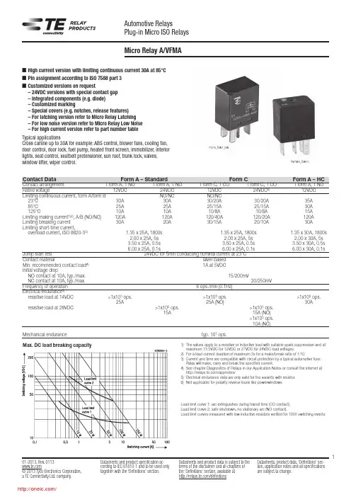
101-2013, Rev. 0113Datasheets and product specification ac-Datasheets and product data is subject to the Datasheets, product data, ‘Definitions’ sec-Micro Relay A/VFMA1) The values apply to a resistive or inductive load with suitable spark suppression and atmaximum 13.5VDC for 12VDC or 27VDC for 24VDC load voltages.2) For a load current duration of maximum 3s for a make/break ratio of 1:10.3) Current and time are compatible with circuit protection by a typical automotive fuse. Relay will make, carry and break the specified current.4) See chapter Diagnostics of Relays in our Application Notes or consult the internet at /appnotes/5) Electrical endurance data are only valid for the variants with resistor.6) Not applicable for polarity reverse loads like powerwindowsn High current version with limiting continuous current 30A at 85°C n Pin assignment according to ISO 7588 part 3n Customized versions on request– 24VDC versions with special contact gap – Integrated components (e.g. diode) – Customized marking– Special covers (e.g. notches, release features) – For latching version refer to Micro Relay Latching – For low noise version refer to Micro Relay Low Noise – For high current version refer to part number table Typical applicationsCross carline up to 30A for example: ABS control, blower fans, cooling fan, door control, door lock, fuel pump, heated front screen, immobilizer, interior lights, seat control, seatbelt pretensioner, sun roof, trunk lock, valves, window lifter, wiper control.Max. DC load breaking capacityLoad limit curve 1: arc extinguishes during transit time (CO contact).Load limit curve 2: safe shutdown, no stationary arc (NO contact).Load limit curves measured with low inductive resistors verified for 1000 switching events.Contact DataForm A – StandardForm C Form A – HCContact arrangement 1 form A, 1 NO 1 form A, 1 NO 1 form C, 1 CO 1 form C, 1 CO 1 form A, 1 NORated voltage 12VDC 24VDC 12VDC 24VDC 6) 12VDCLimiting continuous current, form A/form B NO/NC NO/NC 23°C 30A 30A 30/20A 30/20A 35A 85°C 25A 25A 25/15A 25/15A 30A 125°C 10A 10A 10/8A 10/8A 15ALimiting making current 1)2), A/B (NO/NC) 120A 120A 120/40A 120/20A 120ALimiting breaking current 30A 20A 30/15A 20/10A 30A Limiting short-time current,overload current, ISO 8820-33) 1.35 x 25A, 1800s 1.35 x 25A, 1800s 1.35 x 30A, 1800s 2.00 x 25A, 5s 2.00 x 25A, 5s 2.00 x 30A, 5s 3.50 x 25A, 0.5s 3.50 x 25A, 0.5s 3.50 x 30A, 0.5s 6.00 x 25A, 0.1s 6.00 x 25A, 0.1s 6.00 x 30A, 0.1s Jump start test 24VDC for 5min conducting nominal current at 23°C Contact material silver based Min. recommended contact load 4) 1A at 5VDC Initial voltage drop NO contact at 10A, typ./max. 15/200mV NC contact at 10A, typ./max. 20/250mV Frequency of operation 6 ops./min (0.1Hz)Electrical endurance 5)resistive load at 14VDC >1x10⁵ ops. >1x10⁵ ops. >1x10⁵ ops.25A 25A (NO) 30A resistive load at 28VDC >1x10⁵ ops. >1x10⁵ ops. 15A 15A (NO) >1x10⁵ ops. 10A (NC)Mechanical endurance typ. 107 ops. F074_fcw1_bwFVFMA_fcw1c201-2013, Rev. 0113Datasheets and product specification ac-Datasheets and product data is subject to the Datasheets, product data, ‘Definitions’ sec-Other DataEU RoHS/ELV compliance compliant Ambient temperature -40 to +125°C Climatic cycling with condensation, EN ISO 6988 6 cycles, storage 8/16h Temperature cycling, IEC 60068-2-14, Nb 10 cycles, -40/+85°C (5°C/min) Damp heat cyclic,IEC 60068-2-30, Db, Variant 1 6 cycles, upper air temp. 55°C Damp heat constant,IEC 60068-2-3 (78), Ca 56 days Category of environmental protection, IEC 61810 RT I – dustproof Degree of protection, IEC 60529 IP54 Corrosive gas IEC 60068-2-42 10±2cm 3/m 3 SO 2, 10 days IEC 60068-2-43 1±0.3cm 3/m 3 H 2S, 10 days Vibration resistance (functional) IEC 60068-2-6 (sine sweep) 10 to 500Hz min. 5g 8) Shock resistance (functional) IEC 60068-2-27 (half sine) min. 20g 11ms 8) Drop test, free fall, IEC 60068-2-32 1m onto concrete Terminal type plug-in, QC Cover retention axial force 150N pull force 150N push force 200N Terminal retention pull force 100N push force 100N resistance to bending 10N 9) force applied to side 10N 9) torque 0.3Nm Weight approx. 16 to 20g (0.5 to 0.7oz)Packaging unit Micro A 480 pcs. VFMA 600 pcs.8) No change in the switching state >10µs. Valid for NC contacts, NO contact values significantly higher.9) Values apply 2mm from the end of the terminal. When the force is removed, the terminal must not have moved by more than 0.3mmAccessoriesFor details see datasheetConnectors for Micro ISO RelaysCoil DataCoil voltage range 12/24VDCCoil versions, DC coil Coil Rated Operate Release Coil Rated coil code voltage voltage voltage resistance 7) power 7) VDC VDC VDC Ω±10% W 001 12 7.2 1.6 119 1.20 002 24 14.4 3.6 430 1.34 005 12 7.2 1.6 144 1.00 F 12 7.2 1.2 90 1.60 H 24 14.4 3.6 430 1.34All figures are given for coil without pre-energization, at ambient temperature +23°C.7) Without components in parallel.Insulation DataInitial dielectric strength between open contacts 500VAC rms between contact and coil 500VAC rms Load dump testISO 7637-1 (12VDC), test pulse 5 Vs=+86.5VDC ISO 7637-2 (24VDC), test pulse 5Vs=+200VDCNOD1 form A, 1 NO with diodeNOR1 form A, 1 NO with resistorTerminal Assignment COD1 form C, 1 CO with diodeCOR1 form C, 1 CO with resistor5435435353Does not take into account the temperature rise due to the contact currentE = pre-energization.Does not take into account the temperature rise due to the contact current E = pre-energization Coil operating range301-2013, Rev. 0113Datasheets and product specification ac-Datasheets and product data is subject to the Datasheets, product data, ‘Definitions’ sec-View of the terminals (bottom view)Quick connect terminal similar to ISO 8092-1.Micro A: Terminals without holes401-2013, Rev. 0113Datasheets and product specification ac-Datasheets and product data is subject to the Datasheets, product data, ‘Definitions’ sec-Product code structureTypical product code V23074 -A 1 001 -A4 02Type V23074 Micro Relay A Version A Standard H High current Coil suppression 1 Resistor 2 Diode Coil 001 12VDC 002 24VDC00512VDC for high current versionContact material -A4 Silver based -A5 Silver based for high current version Contact arrangement 02 1 form A, 1 NO031 form C, 1 COProduct code structureTypical product codeVFMA -1 1 F 4 1 -S01Type VFMA VFMA Series Version 1 Standard Contact arrangement 1 1 form A, 1 NO 5 1 form C, 1 COCoil F 12VDC H 24VDC Contact material 4 Silver based 7Silver based for high current versionTerminals 1 Plug-in Coil suppression S01 ResistorOther types on request.This list represents the most common types and does not show all variants covered by this datasheet.分销商库存信息: TE ConnectivityV23074A1002A403。

vfdo07el43a规格书一、产品概述1.1 产品名称:vfdo07el43a1.2 产品型号:vfdo07el43a1.3 产品种类:工业电器1.4 产品用途:用于工业生产过程中的电气控制和保护二、产品技术参数2.1 额定电压:220V2.2 额定电流:40A2.3 额定频率:50Hz2.4 防护等级:IP542.5 绝缘等级:F级2.6 外观尺寸:400mm × 300mm × 200mm2.7 重量:10kg2.8 工作温度:-25℃ ~ +55℃2.9 存储温度:-40℃ ~ +70℃三、产品特点3.1 高性能:采用先进的电子控制技木,性能稳定可靠。
3.2 耐用耐用:采用优质材料,经久耐用,使用寿命长。
3.3 安全可靠:具有多种保护功能,能有效保护设备和人员安全。
3.4 方便维护:结构简单,维护方便,减少维护成本和时间成本。
3.5 安装灵活:体积小巧,易于安装,适用于各种场合。
3.6 环保节能:低能耗、低噪音、无污染,符合环保要求。
四、产品应用vfdo07el43a广泛应用于制药、食品、化工、冶金、机械制造等行业的电气控制系统中,用于电机起停、照明控制、短路保护等方面。
五、产品质量保证5.1 产品执行GB/Txxx-2016《质量管理体系要求》标准。
5.2 出厂产品均经过严格的质量检测和试验,确保产品符合国家标准和行业标准要求。
5.3 对于因产品本身质量问题引起的故障,在保修期内提供免费维修或更换服务。
5.4 全国范围内设有售后服务中心,提供全方位的技术支持和售后服务。
六、产品包装和运输vfdo07el43a产品采用木箱包装,防止在运输过程中受到损坏。
运输方式根据客户需求和实际情况选择,可采用陆运、海运或空运。
七、售后服务承诺7.1 为客户提供产品安装调试指导和技术交流服务。
7.2 定期进行客户回访,了解产品使用情况和客户需求,为客户提供更好的服务。
7.3 对于客户提出的产品质量问题和技术问题,24小时内做出回应,并尽快解决。

Rev. B Document Feedback Information furnished by Analog Devices is believed to be accurate and reliable. However, no responsibility is assumed by Analog Devices for its use, nor for any infringements of patents or other rights of third parties that may result from its use. Specifications subject to change without notice. No license is granted by implication or otherwise under any patent or patent rights of Analog Devices. Trademarks andregistered trademarks are the property of their respective owners.One Technology Way, P.O. Box 9106, Norwood, MA 02062-9106, U.S.A.Tel: 781.329.4700 ©2019 Analog Devices, Inc. All rights reserved. Technical Support /cnADI 中文版数据手册是英文版数据手册的译文,敬请谅解翻译中可能存在的语言组织或翻译错误,ADI 不对翻译中存在的差异或由此产生的错误负责。
如需确认任何词语的准确性,请参考ADI 提供的最超紧凑1.5 A 热电冷却器(TEC)控制器数据手册ADN8834产品特性获得专利的高效率单电感架构用于TEC 控制器的集成式低R DSON MOSFET TEC 电压和电流工作监控 无需外部检测电阻独立的TEC 加热和冷却限流设置 可编程最大TEC 电压2.0 MHz PWM 驱动器开关频率 外部同步集成两个零点漂移、轨到轨斩波放大器 支持NTC 或RTD 热传感器2.50 V 、1%精度基准电压输出 温度锁定指示器 采用25引脚、2.5 mm x 2.5 mm WLCSP 或24引脚、4 mm x 4 mm LFCSP 封装应用TEC 温度控制 光学模块 光纤放大器 光纤网络系统需要TEC 温度控制的仪器仪表功能框图图1.概述ADN88341是一款集成TEC 控制器的单芯片TEC 控制器。