机器人模糊避障外文翻译
- 格式:doc
- 大小:420.50 KB
- 文档页数:10
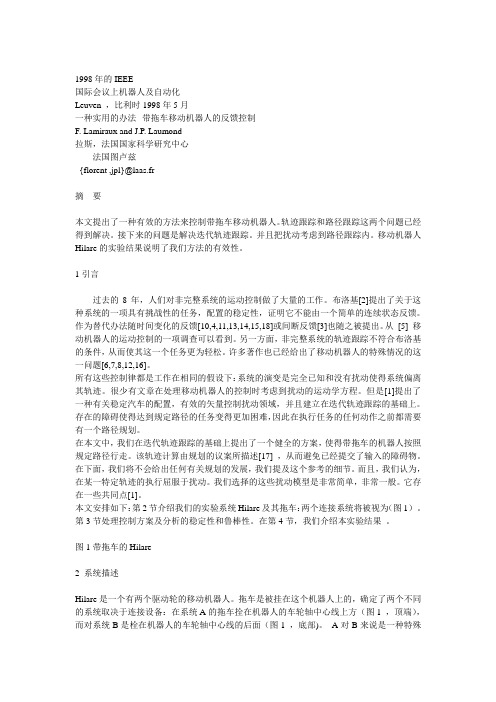
1998年的IEEE国际会议上机器人及自动化Leuven ,比利时1998年5月一种实用的办法--带拖车移动机器人的反馈控制F. Lamiraux and J.P. Laumond拉斯,法国国家科学研究中心法国图卢兹{florent ,jpl}@laas.fr摘要本文提出了一种有效的方法来控制带拖车移动机器人。
轨迹跟踪和路径跟踪这两个问题已经得到解决。
接下来的问题是解决迭代轨迹跟踪。
并且把扰动考虑到路径跟踪内。
移动机器人Hilare的实验结果说明了我们方法的有效性。
1引言过去的8年,人们对非完整系统的运动控制做了大量的工作。
布洛基[2]提出了关于这种系统的一项具有挑战性的任务,配置的稳定性,证明它不能由一个简单的连续状态反馈。
作为替代办法随时间变化的反馈[10,4,11,13,14,15,18]或间断反馈[3]也随之被提出。
从[5] 移动机器人的运动控制的一项调查可以看到。
另一方面,非完整系统的轨迹跟踪不符合布洛基的条件,从而使其这一个任务更为轻松。
许多著作也已经给出了移动机器人的特殊情况的这一问题[6,7,8,12,16]。
所有这些控制律都是工作在相同的假设下:系统的演变是完全已知和没有扰动使得系统偏离其轨迹。
很少有文章在处理移动机器人的控制时考虑到扰动的运动学方程。
但是[1]提出了一种有关稳定汽车的配置,有效的矢量控制扰动领域,并且建立在迭代轨迹跟踪的基础上。
存在的障碍使得达到规定路径的任务变得更加困难,因此在执行任务的任何动作之前都需要有一个路径规划。
在本文中,我们在迭代轨迹跟踪的基础上提出了一个健全的方案,使得带拖车的机器人按照规定路径行走。
该轨迹计算由规划的议案所描述[17] ,从而避免已经提交了输入的障碍物。
在下面,我们将不会给出任何有关规划的发展,我们提及这个参考的细节。
而且,我们认为,在某一特定轨迹的执行屈服于扰动。
我们选择的这些扰动模型是非常简单,非常一般。
它存在一些共同点[1]。

外文资料FUZZY LOGIC CONTROL FOR ROBOT MAZE TRA VERSAL: ANUNDERGRADUATE CASE STUDYJames Wolfer Chad A. GeorgeAbstractAs previously reported, Indiana University South Bend has deployed autonomous robots in their Computer Organization course to facilitate introducing computer science students to the basics of logic, embedded systems, and assembly language. The robots help to provide effective, real-time feedback on program operation and to make assembly language less abstract. As a part of their coursework students are required to program a sensor-based traversal of a maze. This paper details one solution to this problem employing a fuzzy logic controller to create linguistic rules.Key words:Fuzzy logic, pedagogy, robots, student projectsINTRODUCTIONAssembly language programming in a computer science environment is often taught using abstract exercises to illustrate concepts and encourage student proficiency.To augment this approach we have elected to provide hands-on, real-world experience to our students by introducing robots into our assembly language class.Observing the physical action of robots can generate valuable feedback and have real-world consequences – robots hitting walls make students instantly aware of program errors, for example.It also provides insight into the realities of physical machines such as motor control, sensor calibration, and noise. To help provide a meaningful experience for our computer organization students, we reviewed the course with the following objectives in mind:• Expand the experience of our students in a manner that enhances the student's insight, provides a hands-on, visual, environment for them to learn, and forms an integrated component for future classes.•Remove some of the abstraction inherent in the assembly language class. Specifically, to help enhance the error detection environment.• Provide a kinesthetic aspect to our pedagogy.• Build student expertise early in their program that could lead to research projects and advanced classroom activities later in their program. Specifically, in this case, to build expertise to support later coursework in intelligent systems and robotics.As one component in meeting these objectives we, in cooperation with the Computer Science department, the Intelligent Systems Laboratory, and the University Center for Excellence in Teaching, designed a robotics laboratory to support the assembly language portion of the computer organization class as described in [1].The balance of this report describes one example project resulting from this environment. Specifically, we describe the results of a student project developing an assembly language fuzzy engine, membership function creation, fuzzy controller, and resulting robot behavior in a Linux-based environment.We also describe subsequent software devlopment in C# under Windows, including graphical membership tuning, real-time display of sensor activation, and fuzzy controller system response. Collectively these tools allow for robust controller development, assemblylanguage support, and an environment suitable for effective classroom and publicdisplay.BACKGROUNDRobots have long been recognized for their potential educational utility, with examples ranging from abstract, simulated, robots, such as Karel[2] and Turtle[3] for teaching programming and geometry respectively, to competitive events such as robotic soccer tournaments[4].As the cost of robotics hardware has decreased their migration into the classroom has accelerated [5, 6]. Driven by the combined goals for this class and the future research objectives, as well as software availability, we chose to use off-the-shelf, Khepera II, robots from K-Team[7].SIMULATED ROBOT DIAGRAMThe K-Team Kephera II is a small, two-motor robot which uses differential wheel speed for steering. Figure 1 shows a functional diagram of the robot. In addition to thetwo motors it includes a series of eight infrared sensors, six along the “front” and two in the “back”of the robot. This robot also comes with an embedded system-call library, a variety of development tools, and the availability of several simulators. The embedded code in the Khepera robots includes a relatively simple, but adequate, command level interface which communicates with the host via a standard serial port. This allows students to write their programs using the host instruction set (Intel Pentium in this case), send commands, and receive responses such as sensor values, motor speed and relative wheel position.We also chose to provide a Linux-based programming environment to our students by adapting and remastering the Knoppix Linux distribution [9]. Our custom distribution supplemented Knoppix with modified simulators for the Khepera, the interface library (including source code),manuals, and assembler documentation. Collectively, this provides a complete development platform.The SIM Kheperasimulator[8] includes source code in C, and provides a workable subset of the native robot command language. It also has the ability to redirect input and output to the physical robot from the graphics display. Figure 2 shows the simulated Khepera robot in a maze environment and Figure 3 shows an actual Khepera in a physical maze. To provide a seamless interface to the simulator and robots we modified the original simulator to more effectively communicate through a pair of Linuxpipes, and we developed a small custom subroutine library callable from the student's assembly language programs.Assignments for the class range from initial C assignments to call the robot routines to assembly language assignments culminating in the robot traversing the maze. FUZZY CONTROLLEROne approach to robot control, fuzzy logic, attempts to encapsulate important aspects of human decision making. By forming a representation tolerant of vague, imprecise, ambiguous, and perhaps missing information fuzzy logic enhances the ability to deal with real-world problems. Furthermore, by empirically modeling a system engineering experience and intuition can be incorporated into a final design.Typical fuzzy controller design [10] consists of:• Defining the control objectives and criteria• Determining the input and output relationships• Creating fuzzy membership functions, along withsubsequent rules, to encapsulate a solution fromintput to output.• Apply necessary input/output conditioning• Test, evaluate, and tune the resulting system.Figure 4 illustrates the conversion from sensor input to a fuzzy-linguistic value. Given three fuzzy possibilities, …too close‟, …too far‟, and …just right‟, along with a sensor reading we can ascertain the degree to which the sensor reading belongs to each of these fuzzy terms. Note that while Figure 4 illustrates a triangular membership set, trapezoids and other shapes are also common.Once the inputs are mapped to their corresponding fuzzy sets the fuzzy attributes are used, expert system style, to trigger rules governing the consequent actions, in this case, of the robot.For example, a series of rules for a robot may include:• If left-sensor is too close and right sensor is too far then turn right.• If left sensor is just right and forward sensor is too far then drive straight.• If left sensor is too far and forward sensor is too far then turn left.• If forward sensor is close then turn right sharply.The logical operators …and‟, …or‟, and …not‟ are calculated as follows: …and‟ represents set intersection and is calculated as the minimum value, …or‟ is calculated as the maximum value or the union of the sets, and …not‟ finds the inverse of the set, calculated as 1.0-fitness.Once inputs have been processed and rules applied, the resulting fuzzy actions must be mapped to real-world control outputs. Figure 5 illustrates this process. Here output is computed as the coordinate of the centroid of the aggregate area of the individual membership sets along the horizontal axis.ASSEMBLY LANGUAGE IMPLEMENTATIONTwo implementations of the fuzzy robot controller were produced. The first was written in assembly language for the Intel cpu architecture under the Linux operating system, the second in C# under Windows to provide a visually intuitive interface for membership set design and public demonstration.Figure 6 shows an excerpt of pseudo-assembly language program. The actual program consists of approximately eight hundred lines of hand-coded assembly language. In the assembly language program subroutine calls are structured with parameters pushed onto the stack. Note that the code for pushing parameters has been edited from this example to conserve space and to illustrate the overall role of the controller. In this code-fragment the …open_pipes‟ routine establishes contact with the simulator or robot. Once communication is established, a continous loop obtains sensor values, encodes them as fuzzy inputs, interprets them through the rule base to linguistic output members which are then converted to control outputs which are sent to the robot. The bulk of the remaining code implements the fuzzy engine itself.FUZZY CONTROLLER MAIN LOOPMembership sets were manually defined to allow the robot to detect and track walls, avoid barriers, and negotiate void spaces in it field of operation. Using this controller, both the simulated robot and the actual Khepera successfully traversed a variety of maze configurations.ASSEMBLY LANGUAGE OBSERV ATIONSWhile implementing the input fuzzification and output defuzzification in assembly language was tedious compared with the same task in a high level language, the logic engine proved to be well suited to description in assembly language.The logic rules were defined in a type of psuedo-code using …and‟, …or‟, …not‟ as operators and using the fuzzy input and output membership sets as parameters. With the addition of input, output and flow control operators, the assembly language logic engine simply had to evaluate these psuedo-code expressions in order to map fuzzy inputs memberships to fuzzy output memberships.Other than storing the current membership fitness values from the inputfuzzyfication, the only data structure needed for the logic engine is a stack to hold intermediate calculations. This is convenient under assembly language since the CPUs stack is immediately available as well as the nescesary stack operators.There were seven commands implemented by the logic rule interpreter: IN, OUT, AND, OR, NOT, DONE, and EXIT.•IN – reads the current fitness from an input membership set and places the value on the stack.•OUT – assigns the value on the top of the stack as the fitness value of an output membership set if it is greater than the existing fitness value for that set.•AND – performs the intersection operation by replacing the top two elements on the stack with the minimum element.•OR – performs the union operation by replace the top two elements on the stack with their maximum.•NOT – replaces the top value on the stack with its compliment.•DONE – pops the top value off the stack to prepare for the next rule•EXIT – signals the end of the logic rule definition and exits the interpreter.As an example the logic rule “If left-sensor is too close and right sensor is too far then turn right”, might be define d by the following fuzzy logic psuedo-code: IN, left_sensor[ TOO_CLOSE ]IN, right_sensor[ TOO_FAR ] ANDOUT, left_wheel[ FWD ]OUT, right_wheel[ STOP ]DONEEXITBy utilizing the existing CPU stack and implementing the logic engine as anpsuedo-code interpreter, the assembly language version is capable of handling arbitrarily complicated fuzzy rules composed of the simple logical operators provided. IMPLEMENTATIONWhile the assembly language programming was the original focus of the project, ultimately we felt that a more polished user interface was desirable for membership set design, fuzzy rule definition, and controller response monitoring. To provide these facilities the fuzzy controller was reimplemented in C# under Windows. through 10 illustrate the capabilities of the resulting software. Specifically, Figure 7 illustrates user interface for membership defination, in this case …near‟. Figure 8 illustrates theinterface for defining the actual fuzzy rules. Figure 9 profiles the output response with respect to a series of simulated inputs. Finally, real-time monitoring of the system is also implemented as illustrated in 10 which shows the robot sensor input values.Since the Khepera simulator was operating system specific, the C# program controls the robot directly. Again, the robot was successful at navigating the maze using a controller specified with this interface.SUMMARYTo summarize, we have developed a student-centric development environment for teaching assembly language programming. As one illustration of its potential we profiled a project implementing a fuzzy-logic engine and controller, along with a subsequent implementation in the C# programming language. Together these projects help to illustrate the viability of a robot-enhanced environment for assembly language programming.REFERENCES[1] Wolfer, J &Rababaah, H. R. A., “Creating a Hands-On Robot Environment for Teaching Assembly Language Programming”, Global Conference on Engineering and Technology Education, 2005[2] Pattic R.E., Karel the Robot: a gentle introduction to the art of programming, 2nd edition. Wiley, 1994[3] Abelson H. and diSessa A., Turtle geometry: the computer as a medium for exploring mathematics. MIT Press, 1996[4] Amirijoo M., Tesanovic A., and Nadjm-Tehrani S., “Raising motivation in real-time laboratories: the soccer scenario” in SIGCSE Technical Symposium on Computer Sciences Education, pp. 265-269, 2004.[5] Epp E.C., “Robot control and embedded systems on inexpensive linux platforms workshop,” in SIGCSE Technical Symposium on Computer Science Education, p. 505, 2004[6] Fagin B. and Merkle L., “Measuring the effectiveness of robots in teaching computer science,” in SIGCSE Technical Symposium on Computer Science Education, PP. 307-311, 2003.[7] K-Team Khepera Robots, , accessed 09/06/05.[8] Michel O., “Khepera Simulator package version 2.0: Freeware mobile robot simulator written at the university of nice Sophia-Antipolis by Olivier Michel. Downloadable from the world wide web. http://diwww.epfl.ch/lami/team/michel/khep-sim, accessed 09/06/05.[9] Knoppix Official Site, , accessed 09/06/05.[10] Earl Cox., The Fuzzy Systems Handbook, Academic Press, New York, 1999.模糊逻辑控制机器人走迷宫James Wolfer Chad A. George摘要美国印第安纳大学南本德已部署在他们的计算机组织课程自主机器人,以方便学生介绍计算机科学逻辑的基础知识,嵌入式系统和汇编语言。

介绍robot的高考英语书面表达《Robots》一、英语释义1. A robot is a machine - especially one programmable by aputer - capable of carrying out aplex series of actions automatically. (机器人是一种机器,尤其是一种可由计算机编程、能够自动执行一系列复杂动作的机器。
)二、相关短语1. industrial robot 工业机器人2. robot arm 机器人手臂3. service robot 服务机器人4. robot technology 机器人技术5. human - like robot 类人机器人6. robot control 机器人控制7. robot system 机器人系统8. mobile robot 移动机器人9. intelligent robot 智能机器人10. surgical robot 手术机器人三、相关单词及用法1. automation [ˌɔːtəˈmeɪʃn]- 用法:名词,意为“自动化;自动操作”。
- 例句:Automation has led to increased productivity in factories.(自动化提高了工厂的生产率。
)2. mechanism [ˈmekənɪzəm]- 用法:名词,“机制;原理;机械装置”。
- 例句:The robot has aplex mechanism.(这个机器人有一个复杂的机械装置。
)3. program [ˈprəʊɡræm]- 用法:作动词时,意为“编程;编制程序”;作名词时,“程序;计划”。
- 例句:He programs the robot to perform different tasks.(他给机器人编程以执行不同的任务。
)- The program for the robot needs to be updated regularly.(机器人的程序需要定期更新。

外文资料FUZZY LOGIC CONTROL FOR ROBOT MAZE TRA VERSAL: ANUNDERGRADUATE CASE STUDYJames WolferChad A. GeorgeAbstractAs previously reported, Indiana University South Bend has deployed autonomous robots in their Computer Organization course to facilitate introducing computer science students to the basics of logic, embedded systems, and assembly language. The robots help to provide effective, real-time feedback on program operation and to make assembly language less abstract. As a part of their coursework students are required to program a sensor-based traversal of a maze. This paper details one solution to this problem employing a fuzzy logic controller to create linguistic rules.Key words:Fuzzy logic, pedagogy, robots, student projectsINTRODUCTIONAssembly language programming in a computer science environment is often taught using abstract exercises to illustrate concepts and encourage student proficiency.To augment this approach we have elected to provide hands-on, real-world experience to our students by introducing robots into our assembly language class.Observing the physical action of robots can generate valuable feedback and have real-world consequences –robots hitting walls make students instantly aware of program errors, for example.It also provides insight into the realities of physical machines such as motor control, sensor calibration, and noise. To help provide a meaningful experience for our computer organization students, we reviewed the course with the following objectives in mind:• Expand the experience of our students in a manner that enhances the student's insight, provides a hands-on, visual, environment for them to learn, and forms an integrated component for future classes.•Remove some of the abstraction inherent in the assembly language class. Specifically, to help enhance the error detection environment.• Provide a kinesthetic aspect to our pedagogy.• Build student expertise early in their program that could lead to research projects and advanced classroom activities later in their program. Specifically, in this case, to build expertise to support later coursework in intelligent systems and robotics.As one component in meeting these objectives we, in cooperation with the Computer Science department, the Intelligent Systems Laboratory, and the UniversityCenter for Excellence in Teaching, designed a robotics laboratory to support the assembly language portion of the computer organization class as described in [1].The balance of this report describes one example project resulting from this environment. Specifically, we describe the results of a student project developing an assembly language fuzzy engine, membership function creation, fuzzy controller, and resulting robot behavior in a Linux-based environment.We also describe subsequent software devlopment in C# under Windows,including graphical membership tuning, real-time display of sensor activation, and fuzzy controller system response. Collectively these tools allow for robust controller development, assemblylanguage support, and an environment suitable for effective classroom and public display.BACKGROUNDRobots have long been recognized for their potential educational utility, with examples ranging from abstract, simulated, robots, such as Karel[2] and Turtle[3] for teaching programming and geometry respectively, to competitive events such as robotic soccer tournaments[4].As the cost of robotics hardware has decreased their migration into the classroom has accelerated [5, 6]. Driven by the combined goals for this class and the future researchobjectives, as well as software availability, we chose to use off-the-shelf, Khepera II, robots from K-Team[7].SIMULATED ROBOT DIAGRAMThe K-Team Kephera II is a small, two-motor robot which uses differential wheel speed for steering. Figure 1 shows a functional diagram of the robot. In addition to thetwo motors it includes a series of eight infrared sensors, six along the “front” and two in the “back” of the robot. This robot also comes with an embedded system-call library, a variety of development tools, and the availability of several simulators. The embedded code in the Khepera robots includes a relatively simple, but adequate, command level interface which communicates with the host via a standard serial port. This allows students to write their programs using the host instruction set (Intel Pentium in this case), send commands, and receive responses such as sensor values, motor speed and relative wheel position.We also chose to provide a Linux-based programming environment to our students by adapting and remastering the Knoppix Linux distribution [9]. Our custom distribution supplemented Knoppix with modified simulators for the Khepera, the interface library (including source code),manuals, and assembler documentation. Collectively, this provides a complete development platform.The SIM Kheperasimulator[8] includes source code in C, and provides aworkable subset of the native robot command language. It also has the ability to redirect input and output to the physical robot from the graphics display. Figure 2 shows the simulated Khepera robot in a maze environment and Figure 3 shows an actual Khepera in a physical maze. To provide a seamless interface to the simulator and robots we modified the original simulator to more effectively communicate through a pair of Linux pipes, and we developed a small custom subroutine library callable from the student's assembly language programs.Assignments for the class range from initial C assignments to call the robot routines to assembly language assignments culminating in the robot traversing the maze.FUZZY CONTROLLEROne approach to robot control, fuzzy logic, attempts to encapsulate important aspects of human decision making. By forming a representation tolerant of vague, imprecise, ambiguous, and perhaps missing information fuzzy logic enhances the ability to deal with real-world problems. Furthermore, by empirically modeling a system engineering experience and intuition can be incorporated into a final design.Typical fuzzy controller design [10] consists of:• Defining the control objectives and criteria• Determining the input and output relationships• Creating fuzzy membership functions, along withsubsequent rules, to encapsulate a solution fromintput to output.• Apply necessary input/output conditioning• Test, evaluate, and tune the resulting system.Figure 4 illustrates the conversion from sensor input to a fuzzy-linguistic value. Given three fuzzy possibilities, …too close‟, …too far‟, and …just right‟, along with a sensor reading we can ascertain the degree to which the sensor reading belongs to each of these fuzzy terms. Note that while Figure 4 illustrates a triangular membership set, trapezoids and other shapes are also common.Once the inputs are mapped to their corresponding fuzzy sets the fuzzy attributes are used, expert system style, to trigger rules governing the consequent actions, in this case, of the robot.For example, a series of rules for a robot may include: • If left-sensor is too close and right sensor is too far then turn right.• If left sensor is just right and forward sensor is too far then drive straight.• If left sensor is too far and forward sensor is too far then turn left.• If forward sensor is close then turn right sharply.The logical operators …and‟, …or‟, and …not‟ are calculated as follows: …and‟ represents set intersection and is calculated as the minimum value, …or‟ is calculated as the maximum value or the union of the sets, and …not‟ finds the inverse of the set, calculated as 1.0-fitness.Once inputs have been processed and rules applied, the resulting fuzzy actions must be mapped to real-world control outputs. Figure 5 illustrates this process. Here output is computed as the coordinate of the centroid of the aggregate area of the individual membership sets along the horizontal axis.ASSEMBLY LANGUAGE IMPLEMENTATIONTwo implementations of the fuzzy robot controller were produced. The first was written in assembly language for the Intel cpu architecture under the Linux operating system, the second in C# under Windows to provide a visually intuitive interface for membership set design and public demonstration.Figure 6 shows an excerpt of pseudo-assembly language program. The actual program consists of approximately eight hundred lines of hand-coded assembly language. In the assembly language program subroutine calls are structured with parameters pushed onto the stack. Note that the code for pushing parameters has been edited from this example to conserve space and to illustrate the overall role of the controller. In this code-fragment the …open_pipes‟ routine establishes contact with the simulator or robot. Once communication is established, a continous loop obtains sensor values, encodes them as fuzzy inputs, interprets them through the rule base to linguistic output members which are then converted to control outputs which are sent to the robot. The bulk of the remaining code implements the fuzzy engine itself.FUZZY CONTROLLER MAIN LOOPMembership sets were manually defined to allow the robot to detect and track walls, avoid barriers, and negotiate void spaces in it field of operation. Using this controller, both the simulated robot and the actual Khepera successfully traversed a variety of maze configurations.ASSEMBLY LANGUAGE OBSERV ATIONSWhile implementing the input fuzzification and output defuzzification in assembly language was tedious compared with the same task in a high level language,the logic engine proved to be well suited to description in assembly language.The logic rules were defined in a type of psuedo-code using …and‟, …or‟, …not‟ as operators and using the fuzzy input and output membership sets as parameters. With the addition of input, output and flow control operators, the assembly language logic engine simply had to evaluate these psuedo-code expressions in order to map fuzzy inputs memberships to fuzzy output memberships.Other than storing the current membership fitness values from the input fuzzyfication, the only data structure needed for the logic engine is a stack to hold intermediate calculations. This is convenient under assembly language since the CPUs stack is immediately available as well as the nescesary stack operators.There were seven commands implemented by the logic rule interpreter: IN, OUT, AND, OR, NOT, DONE, and EXIT.•IN – reads the current fitness from an input membership set and places the value on the stack.•OUT – assigns the value on the top of the stack as the fitness value of an output membership set if it is greater than the existing fitness value for that set.•AND – performs the intersection operation by replacing the top two elements on the stack with the minimum element.•OR – performs the union operation by replace the top two elements on the stack with their maximum.•NOT – replaces the top value on the stack with its compliment.•DONE – pops the top value off the stack to prepare for the next rule•EXIT – signals the end of the logic rule definition and exits the interpreter.As an example the logic rule “If left-sensor is too close and right sensor is too far then turn right”, might be define d by the following fuzzy logic psuedo-code: IN, left_sensor[ TOO_CLOSE ]IN, right_sensor[ TOO_FAR ] ANDOUT, left_wheel[ FWD ]OUT, right_wheel[ STOP ]DONEEXITBy utilizing the existing CPU stack and implementing the logic engine as anpsuedo-code interpreter, the assembly language version is capable of handling arbitrarily complicated fuzzy rules composed of the simple logical operators provided.IMPLEMENTATIONWhile the assembly language programming was the original focus of the project, ultimately we felt that a more polished user interface was desirable for membership set design, fuzzy rule definition, and controller response monitoring. To provide these facilities the fuzzy controller was reimplemented in C# under Windows. through 10 illustrate the capabilities of the resulting software. Specifically, Figure 7 illustrates user interface for membership defination, in this case …near‟. Figure 8 illustrates the interface for defining the actual fuzzy rules. Figure 9 profiles the output response with respect to a series of simulated inputs. Finally, real-time monitoring of the system is also implemented as illustrated in 10 which shows the robot sensor input values.Since the Khepera simulator was operating system specific, the C# program controls the robot directly. Again, the robot was successful at navigating the maze using a controller specified with this interface.SUMMARYTo summarize, we have developed a student-centric development environment for teaching assembly language programming. As one illustration of its potential we profiled a project implementing a fuzzy-logic engine and controller, along with a subsequent implementation in the C# programming language. Together these projects help to illustrate the viability of a robot-enhanced environment for assembly language programming.REFERENCES[1] Wolfer, J &Rababaah, H. R. A., “Creating a Hands-On Robot Environment for Teaching Assembly Language Programming”, Global Conference on Engineering and Technology Education, 2005[2] Pattic R.E., Karel the Robot: a gentle introduction to the art of programming, 2nd edition. Wiley, 1994[3] Abelson H. and diSessa A., Turtle geometry: the computer as a medium for exploring mathematics. MIT Press, 1996[4] Amirijoo M., Tesanovic A., and Nadjm-Tehrani S., “Raising motivation in real-time laboratories: the soccer scenario” in SIGCSE Technical Symposium on Computer Sciences Education, pp. 265-269, 2004.[5] Epp E.C., “Robot control and embedded systems on inexpensive linux platf orms workshop,” in SIGCSE Technical Symposium on Computer Science Education, p. 505, 2004[6] Fagin B. and Merkle L., “Measuring the effectiveness of robots in teaching computer science,” in SIGCSE Technical Symposium on Computer Science Education, PP. 307-311, 2003.[7] K-Team Khepera Robots, , accessed 09/06/05.[8] Michel O., “Khepera Simulator package version 2.0: Freeware mobile robot simulator written at the university of nice Sophia-Antipolis by Olivier Michel. Downloadable from the world wide web. http://diwww.epfl.ch/lami/team/michel/khep-sim, accessed 09/06/05.[9] Knoppix Official Site, , accessed 09/06/05.[10] Earl Cox., The Fuzzy Systems Handbook, Academic Press, New York, 1999.模糊逻辑控制机器人走迷宫James WolferChad A. George摘要美国印第安纳大学南本德已部署在他们的计算机组织课程自主机器人,以方便学生介绍计算机科学逻辑的基础知识,嵌入式系统和汇编语言。

Robots机器人中英文翻译Robots机器人With advancements in technology, robots have become an integral part of our daily lives. From manufacturing industries to healthcare and even our homes, robots are taking over various tasks and transforming the way we live. In this article, we will explore the significance of robots and discuss their benefits and drawbacks.机器人在科技的进步下,在我们的日常生活中变得不可或缺。
从制造业到医疗保健,甚至到我们的家庭,机器人正在接管各种任务,改变着我们的生活方式。
本文中,我们将探讨机器人的重要性,并讨论他们的利与弊。
1. The Advantages of Robots 机器人的优势Robots offer numerous benefits in various aspects of our society. Firstly, they improve productivity and efficiency in industries. With their precision and speed, robots can carry out tasks more accurately and faster compared to humans. This leads to increased production rates and reduced errors, ultimately resulting in cost savings for businesses.Secondly, robots minimize the risk to humans in dangerous and hazardous situations. They can be programmed to perform tasks in hazardous environments such as nuclear power plants, mines, or disaster-stricken areas. This reduces the chances of human injuries or fatalities.Thirdly, robots contribute to medical advancements by assisting in surgeries and healthcare. Surgical robots, for example, aid doctors inperforming intricate procedures with enhanced precision and control. Furthermore, robots can also assist with patient care, such as providing support to the elderly or individuals with disabilities.机器人在我们社会的各个方面都提供了众多的优势。

外文原文:Mobile Robot Navigation using Modified Flexible Vector Field Approach with Laser Range Finder and IR sensor Jinpyo Hong ,Youjun Choi and Kyihwan ParkAbstract: In the public space, a mobile robot is adopted as a guider. For guiding a person to the goal position, the mobile robot should make the safe path ,avoid the obstacles and navigate the generated path well. In general, Laser Range Finder is used for the detection of the map around the mobile robot. We propose mobile robot navigation method using our developed a Modified Flexible Vector Field Approach with Laser Range Finder and IR sensor which is used for detecting the emergency status because it has higher response frequency than that of LRF. We will verify that our proposed control scheme and obstacle avoidance algorithm are useful enough to apply to the mobile robot control in the public space by showing experimental results.Keywords: Mobile robot navigation, MFVFA(Modified Flexible Vector Field Approach, LRF(Laser Range Finder), IR sensor)1. INTRODUCTIONWhen a mobile robot is operated as a guider in the public spaces such as a market, a post office, a museumand so on, the most important functionality is the ability to find the path to reach a goal and navigate the goal position. However, In the public space, since there are many obstacles like a shelf, a chair and a person, the mobile robot should avoid the obstacles and reach the goal position simultaneously. For the purpose of navigate the target position, many researchers have addressed a potential field method[1][2], a vector field histogram[3] [5] and a dynamic window approach[6]. Since the market is composed of many narrow passageways and a lot obstacles, there are some difficulty to apply the potential field into our robot as a market application as follows: 1) It is hard to find the passage in the close spaced obstacles. 2) There is an oscillation motion when the robot moves in the narrow passageways. Also the vector field histogram is sensitive to thechange of the environmental map but it can not find the shortest path to reach the goal because we only get the angle information for the mobile robot to go through. The dynamic window uses the heading to goal, distance to obstacles and the velocity of the mobile robot as parameters. Since the dynamic window has an optimisation process for finding the best velocity, this solution is not unique to the shortest path for avoiding the obstacle. For the safe and stable operation of the mobile robot in the public space, a new navigation method is essentially needed which is sensitive to the change of the environment and capable of moving in the shortest path as a guider. Therefore, we proposed a new mobile robot navigation method using modified flexible vector field approach with Laser Range Finder(LRF) and Infra Red(IR) sensor. In our proposed method, since the path informationis obtained from the geometric relation of the obstacle as a circle and the mobile robot as a point, the processing load can be decreased. Since our developed mobile robot has a differential drive structure, the stable velocity of the mobile robot should be firstly considered in this kinematic condition when the mobile robot is controlled toward the generated path. Usually, if the path planner and the path tracker are divided, the various tracking control method are existed like as sliding mode, linearization, backstepping, neural networks, neuro-fuzzy systems. However, the generated root velocity command using those conventional control approaches start with a very large value, and suffers from velocity jumps when sudden tracking errors occur. Therefore, we propose a new velocity profiling approach guaranteeing the stable movement of the mobile robot in this paper. If we assumed that the initial position of the mobile robot and the goal position are given at the first time, we can generate the reference velocity profile using euclidean distances among the start position , the goal position and the current mobile robot position.2. MOBILE ROBOT PLATFORM AND PATH PLANNING2.1 Mobile robot platformFigure 1 is our developed mobile robot platform, GIMaR. The mobile robot has a differential drive structure that has non-holonomic constraint. It has several sensors for detecting the status around the mobile robot. In this research, we only used two sensorsthat one is LRF for detecting the scan map data and another is IR sensor for emergency stop and obstacle avoidance. These two sensors have advantages and drawbacks respectively. LRF generates the scan map data in detail but it is operated slowly compared with IR sensor. On the other hand, IR sensor operates rapidly compared with LRF but it generates one point data. Therefore, we intend to propose the method combining two sensors data for stable driving control and obstacle avoidance.2.2 Path planningIn order lo reach the goal position, we should know he path before starting lo move. If the map data is given in advance, we can generate the safe path to arrive at the goal position but otherwise, we can not do the entire path. In this paper, we assume as follows.1 .Map data is not given in advanced.2. Only the initial position of the mobile robot and the goal position are given.3. Mobile robot has no slip motion and we can know the position and posture of the mobile robot from the odometry information.Under three assumptions, our proposed path planning strategy is shown in Fig. 2. In Fig. 2. the dangerous region indicates an area that the mobile robot has no collision with obstacles. We can know intuitively (hat red line path is the shortest path in safely. Since we don't have map data in advance, we suggest that we find out the next desired point from the geometric relation of dangerous region circle and the current mobile robot position. Although the obstacle exists anywhere, we can determine the next desired point from the our proposed approach, modified flexible vector field approach(MFVFA) because the path planning process is repealed during scan period continuously.3. MOBILE ROBOT CONTROLA nonholonomic mobile robot can be represented by two coordinate systems which are the world coordinate system XG,YG ,SG and the local coordinate system X L,Y L,6L,. In figure 3, C is the robot center point, d is the distance between the left wheel and the right wheel and b is the distance between the center of the wheel and the caster. V and w mean the linear velocity and the angular velocity of the mobile robot.A freely movable mobile robot that is referred as holo-nomic mobile robot has three degrees of freedom(d.o.f.) X, Y,and 0, However, because of the kinematical constraint, the degrees of the freedom for a nonholonomic mobile robot reduces to two. On the conditions of non-slipping, the kinematic constraint of a nonhomolonomic mobile robot is given asFrom the motion control perspective, our developed mobile robot has 2 d.o.f., v C, w c , where v c is the linear velocity and w c is the angular velocity of the mobile robot.The velocities of the two wheels are represented as the diameter of the wheel, r, and the angular velocity wL, wR. .The linear velocity and angular velocity can be described as the relation of e both wheels' angular velocities as follows.In order to control the mobile robot, the velocities of the two wheels can be divided us two parts: one is the part determining the linear velocity of the mobile robot and another is the part tracking the posture of the mobile robot.VL = V C -W CV R=V C +W CWhere, V C is the linear velocity control part and w c is the angular velocity control part. The objective of the linear velocity control is the velocity control of the mobile robot according to the distance between the robot position and the goal position. In the next subsection, we propose the linear velocity generation method using euclidean distance.The mobile robot can avoid the obstacle by controlling the w c. We will explain the posture error feedback method using MFVFA in the next section.4. SIMULATION AND EXPERIMENTAL RESULTSSince we have suggested the obstacle avoidance algorithm for the purpose of using in the narrow space at the market, shelf-like objects are set in the passageway for a test environment. We made up two sections of the market model as a test environment. The size of the test environment is 6 meter by 6 meter. We assume that there are no people in the test environment. In the experimental results, dotted line indicates the desired position, and the red line indicates laser scanning data.The result of multi-obstacle case is also shown in Fig. 11. As we see this experimental result in Fig. 11, if there are multi-obstacles in the test environments, the proposed algorithm provides the safe passageway that the robot can go through without collision. After that, the algorithm generates the shortest trajectory to approach the desired position.Fig. 10Fig. 10 Simulation Result of Stable Curvature Tracking Algorithm - a) the Right Turning Simulation Result, b) the Left Turning Simulation ResultFig. 10 show simulation results of the stable curvature tracking algorithm. These results show how the robot escapes dangerous region when the robot moves into the dangerous region. Wherever the robot is positioned between the dangerous region and collision region, the robot can be controlled toward the circumference of the dangerous region circle. As shown in Fig. 10, the robot makes flexible vector fields with the direction to out-of-dangerous region according to the location of the robot. Therefore, themobile robot moves to the safe region and follows the stable and shortest path for arriving at the goal position.Fig. 11Fig 11 : Result of the Collision Avoidance between Robot and Multi-Obstacles - (a) before applying the collision avoidance algorithm between robot and multi-obstacles (b) after applying the collision avoidance algorithm between robot and multi-obstacles The Trajectories of the robot are shown in Fig. 12 obtained from the experimental results which are shown in Fig. 11. Fig. 12 shows the result that the robot avoids Obstacles safely. We set F{200,10Q), F(150,120), P(200,100), P(16G,180) as starting positions and P(240,450), P(I30,500), (230,500), (170,600) as desired positions. We move the robot with speed or 70cm/s which is same as the walking speed of the human. We made narrow passageway by adding arbitrary obstacles between starting position and desired position. Since there is an obstacle, the robot avoids obstacles, as shown in Fig.12.Fig. 12Fig. 12: Trajectories of robot after applying obstacle avoidance algorithm(a) trajectory of the robot from (200, 100) to (240, 450[Cm]),(b) trajectory of the robot from (180, 160) to (160, 520) [Cm],(c) trajectory of the robot from (200.100) to (230, 500) [Cm],(d) trajectory of the robot from (160,180) to (170, 600) [Cm].5. CONCLUSIONIn this paper, we discussed about the navigation method using the modified flexible vector field with LRF and IR sensors. The controller was divided to the linear velocity control part and the angular control part. The linear velocity stable profile was created considering the stable mobile robot motion using the euclidean distance. For the angular control part, we found out the NOP using the virtual circle originated on the corner point and the tangential straight line. However, since the mobile robot was existed in the collision region, we could control the mobile robot by using the proposed stable curvature algorithm.REFERENCES[1] O. Khalib, Real-rime obstacle avoidance for manipulators and mobile robots,International Journal of Robotics Research, vol. 5. no. 1, pp. 90-98,1995.[2] Peter Vcclaert and Wim Bogacrts . Ultrasonic Potential Field Sensor for ObstacleAvoidance. IEEE Transaction on Robotics and Automation, vol. 15,No. 4, August iyyy.[3]J. Borenstem and Y. Koren, The vector field histogram -fast obstacle avoidance formobile robots, IEEE Transaction on Robotics and Automation, Vol. 7, No. 3, pp.278-288, 1991.[4] Meng Joo Er and Chang Deng, Obstacle Avoidance of a Mobile Robot Using HybridLearning Ap-proachMLMM Transaction on Industrial Electronics. Vol. 52, No, 3, June 2005.[5] J. Borenstein and Y. Korea, Histogramic In Motion Mapping for Mobile RobotObstacle Avoidance,IEEE IRAN. Robotics and Auto, Vol 7, No. 4, 1991.[6] D. Fox, W. Burgard and S. Thrun, The dynamic window approach to collisionavoidance, IEEE Robotics and Automation Magazine, vol 4, pp.23-33, Mar. 1997 [7] R. Balakrishna and A. Ghosal, Modeling of Slip for Wheeled Mobile Robots, IEEETrans. On Robotics and Automation, pp. 126-132, Feb.. 1995中文译文:移动机器人基于LFR激光探测器和IR的MFVFA方法摘要:在公共空间,移动的机器人可以用作导游者。
外文资料robotThe industrial robot is a tool that is used in the manufacturing environment to increase productivity. It can be used to do routine and tedious assembly line jobs,or it can perform jobs that might be hazardous to the human worker . For example ,one of the first industrial robot was used to replace the nuclear fuel rods in nuclear power plants. A human doing this job might be exposed to harmful amounts of radiation. The industrial robot can also operate on the assembly line,putting together small components,such as placing electronic components on a printed circuit board. Thus,the human worker can be relieved of the routine operation of this tedious task. Robots can also be programmed to defuse bombs,to serve the handicapped,and to perform functions in numerous applications in our society.The robot can be thought of as a machine that will move an end-of-tool ,sensor ,and/or gripper to a preprogrammed location. When the robot arrives at this location,it will perform some sort of task .This task could be welding,sealing,machine loading ,machine unloading,or a host of assembly jobs. Generally,this work can be accomplished without the involvement of a human being,except for programming and for turning the system on and off.The basic terminology of robotic systems is introduced in the following:1. A robot is a reprogrammable ,multifunctional manipulator designed to move parts,material,tool,or special devices through variable programmed motions for the performance of a variety of different task. This basic definition leads to other definitions,presented in the following paragraphs,that give acomplete picture of a robotic system.2. Preprogrammed locations are paths that the robot must follow to accomplish work,At some of these locations,the robot will stop and perform some operation ,such as assembly of parts,spray painting ,or welding .These preprogrammed locations are stored in the robot’s memory and are recalled later for continuousoperation.Furthermore,these preprogrammed locations,as well as other program data,can be changed later as the work requirements change.Thus,with regard to this programming feature,an industrial robot is very much like a computer ,where data can be stoned and later recalled and edited.3. The manipulator is the arm of the robot .It allows the robot to bend,reach,and twist.This movement is provided by the manipulator’s axes,also called the degrees of freedom of the robot .A robot can have from 3 to 16 axes.The term degrees of freedom will always relate to the number of axes found on a robot.4. The tooling and frippers are not part the robotic system itself;rather,they are attachments that fit on the end of the robot’s arm. These attachments connected to the end of the robot’s arm allow the robot to lift parts,spot-weld ,paint,arc-weld,drill,deburr,and do a variety of tasks,depending on what is required of the robot.5. The robotic system can control the work cell of the operating robot.The work cell of the robot is the total environment in which the robot must perform itstask.Included within this cell may be the controller ,the robot manipulator ,a work table ,safety features,or a conveyor.All the equipment that is required in order for the robot to do its job is included in the work cell .In addition,signals from outside devices can communicate with the robot to tell the robot when it should parts,pick up parts,or unload parts to a conveyor.The robotic system has three basic components: the manipulator,the controller,and the power source.A.ManipulatorThe manipulator ,which does the physical work of the robotic system,consists of two sections:the mechanical section and the attached appendage.The manipulator also has a base to which the appendages are attached.Fig.1 illustrates the connectionof the base and the appendage of a robot.图1.Basic components of a robot’s manipulatorThe base of the manipulator is usually fixed to the floor of the work area. Sometimes,though,the base may be movable. In this case,the base is attached to either a rail or a track,allowing the manipulator to be moved from one location to anther.As mentioned previously ,the appendage extends from the base of the robot. The appendage is the arm of the robot. It can be either a straight ,movable arm or a jointed arm. The jointed arm is also known as an articulated arm.The appendages of the robot manipulator give the manipulator its various axes of motion. These axes are attached to a fixed base ,which,in turn,is secured to a mounting. This mounting ensures that the manipulator will in one location.At the end of the arm ,a wrist(see Fig 2)is connected. The wrist is made up of additional axes and a wrist flange. The wrist flange allows the robot user to connect different tooling to the wrist for different jobs.图2.Elements of a work cell from the topThe manipulator’s axes allow it to perform work within a certain area. The area is called the work cell of the robot ,and its size corresponds to the size of the manipulator.(Fid2)illustrates the work cell of a typical assembly ro bot.As the robot’s physical size increases,the size of the work cell must also increase.The movement of the manipulator is controlled by actuator,or drive systems.The actuator,or drive systems,allows the various axes to move within the work cell. The drive system can use electric,hydraulic,or pneumatic power.The energy developed by the drive system is converted to mechanical power by various mechanical power systems.The drive systems are coupled through mechanical linkages.These linkages,in turn,drive the different axes of the robot.The mechanical linkages may be composed of chain,gear,and ball screws.B.ControllerThe controller in the robotic system is the heart of the operation .The controller stores preprogrammed information for later recall,controls peripheral devices,and communicates with computers within the plant for constant updates in production.The controller is used to control the robot manipulator’s movements as well as to control peripheral components within the work cell. The user can program the movements of the manipulator into the controller through the use of a hard-held teach pendant.This information is stored in the memory of the controller for later recall.The controller stores all program data for the robotic system.It can store several differentprograms,and any of these programs can be edited.The controller is also required to communicate with peripheral equipment within the work cell. For example,the controller has an input line that identifies when a machining operation is completed.When the machine cycle is completed,the input line turn on telling the controller to position the manipulator so that it can pick up the finished part.Then ,a new part is picked up by the manipulator and placed into the machine.Next,the controller signals the machine to start operation.The controller can be made from mechanically operated drums that step through a sequence of events.This type of controller operates with a very simple robotic system.The controllers found on the majority of robotic systems are more complex devices and represent state-of-the-art eletronoics.That is,they are microprocessor-operated.these microprocessors are either 8-bit,16-bit,or 32-bit processors.this power allows the controller to be very flexible in its operation.The controller can send electric signals over communication lines that allow it to talk with the various axes of the manipulator. This two-way communication between the robot manipulator and the controller maintains a constant update of the end the operation of the system.The controller also controls any tooling placed on the end of the robot’s wrist.The controller also has the job of communicating with the different plant computers. The communication link establishes the robot as part a computer-assisted manufacturing (CAM)system.As the basic definition stated,the robot is a reprogrammable,multifunctional manipulator.Therefore,the controller must contain some of memory stage. The microprocessor-based systems operates in conjunction with solid-state devices.These memory devices may be magnetic bubbles,random-access memory,floppy disks,or magnetic tape.Each memory storage device stores program information fir or for editing.C.power supplyThe power supply is the unit that supplies power to the controller and the manipulator. The type of power are delivered to the robotic system. One type of power is the AC power for operation of the controller. The other type of power isused for driving the various axes of the manipulator. For example,if the robot manipulator is controlled by hydraulic or pneumatic drives,control signals are sent to these devices causing motion of the robot.For each robotic system,power is required to operate the manipulator .This power can be developed from either a hydraulic power source,a pneumatic power source,or an electric power source.There power sources are part of the total components of the robotic work cell.中文翻译机器人工业机器人是在生产环境中用以提高生产效率的工具,它能做常规乏味的装配线工作,或能做那些对于工人来说是危险的工作,例如,第一代工业机器人是用来在核电站中更换核燃料棒,如果人去做这项工作,将会遭受有害放射线的辐射。
RobotsA robot is an automatically controlled, reprogrammable, multipurpose, mani pulating machine with several reprogrammable axes, which may be either fixed in place or mobile for use in industrial automation applications.The key words are reprogrammable and multipurpose because most single-purpose machines do not meet these two requirements.The term”reprogrammabl e” implies two things:The robot operates according to a written program can b e rewritten to accomdate a variety of manufacturing tasks. The term “multipurp ose” means that the robot can perform many different functions, depending on the program and tooling currently in use.Over the past two decades,the robot has been introduced into industry to perform many monotonous and often unsafe operations. Because robots can per form certain basic tasks more quickly and accurately than humans, they are bei ng increasingly used in various manufacturing industries.Structures of RobotsThe typical structure of industrial robots consists of 4 major components: the manipulator, the end effector, the power supply and control syterm.The manipulator is a mechanical unite that provides motions similar to those of a human arm. It often has a shoulder joint,an elbow and a wrist. It can rotate or slide, strech out and withdraw in every possible direction with certain flexibility.The basic mechanical configurations of the robot manipulator are categorized as Cartesian, cylindrical, spherical and articulated.A robot with a Cartesian geometry can move its gripper to any position within the cube or rectangle defined as its working volum.Cylindrical coordinate robots can move the gripper within a volum that is described by a cylinder. The cylindrical coordinate robot is positioned in the work area by two linear movements in the X and Y directions and one angular rotation about the Z axis.Spherical arm geometry robots have an irregular work envelop. This type of robot has two main variants,vertically articulated and horizontally articulated.The end effector attaches itself to the end of the robot wrist, also called end-of-arm tooling.It is the device intended for performing the designed operations as a human hand can.End effectors are generally custom-made to meet special handling requirements. Mechanical grippers are the most commonly used and are equipped with two or more fingers.The selection of an appropriate end effector for a special application depends on such factors as the payload, enviyonment,reliability,and cost.The power supply is the actuator for moving the robot arm, controlling the joints and operating the end effector. The basic type of power sources include electrical,pneumatic, and hydraulic. Each source of energy and each type of motor has its own characteristics, advantages and limitations. An ac-powered motor or dc-powered motor may be used depending on the system design and applications. These motors convert electrical energy into mechanical energy to power the robot.Most new robots use electrical power supply. Pneumatic actuators have been used for high speed. Nonservo robots and are often used for powering tooling such as grippers. Hydraulic actuators have been used for heavier lift systems, typically where accuracy was not also requied.The contro system is the communications and information-processing system that gives commands for the movements of the robot. It is the brain of the robot; it sends signals to the power source to move the robot arm to a specific position and to the end effector.It is also the nerves of the robot; it is reprogrammable to send out sequences of instructions for all movements and actions to be taken by the robot.A open-loop controller is the simplest for of the control system, which controls the robot only by foolowing the predetermined step-by-step instructions.This system dose not have a self-correcting capability.A close-loop control system use feedback sensors to produce signals that reflct the current states of the controed objects. By comparing those feedback signals with the values set by the programmer, the close-loop controller can conduct the robot to move to the precise position and assume the desired attitude, and the end effector can perform with very high accuracy as the close-loop control system can minimize the discrepancy between the controlled object and the predetermined references.Classification of RobotIndustrial robots vary widely in size,shape, number of axes,degrees of freedom, and design configuration. Each factor influence the dimensions of the robot’s working envelop or the volume of space within which it can move and perform its designated task. A broader classification of robots can been described as below.Fixed-and Variable-Sequence Robots. The fixed-sequence robot (also called a pick-and place robot) is programmed for a specific sequence of operations. Its movements are form point to point, and the cycle is repeated continuously.The variable-sequence robot can be programmed for a specific sequence of operations but can be programmed to perform another sequence of operation.Playback Robot. An operator leads or walks the playback robot and its end effector through the desired path. The robot memorizes and records the path and sequence of motions and can repeat them continually without any further action or guidance by the operator.Numerically Controlled Robot. The numerically controlled robot is programmed and operated much like a numerically controlled machine. The robot is servocontrolled by digital data, and its sequence of movements can be changed with relative ease.Intelligent Robot. The intelligent robot is capable of performing some of the functions and tasks carried out by huanbeings.It is equipped with a variety of sensors with visual and tactile capabilities.Robot ApplicationsThe robot is a very special type of productin tool; as a result, the applications in which robots are used are quite broad. These applications can be grouped into three categories: material processing, material handling and assembly.In material processing, robots use tools to process the raw material. For example, the robot tools could include a drill and the robot would be able to perfor drilling operaytions on raw material.Material handling consists of the loading, unloading, and transferring of workpieces in manufacturing facilities. These operations can be performed relatively and repeatedly with robots, thereby improving quality and scrap losses.Assembly is another large application area for using robotics. An automatic assembly system can incorporate automatic testing, robot automation and mechanical handling for reducing labor costs, increasing output and eliminating manual handling concers.机器人机器人是一种自动控制的、可重复编程的、多功能的、由几个可重复编程的坐标系来操纵机器的装置,它可以被固定在某地,还可以是移动的以在工业自动化工厂中使用。
机器人的积极和消极影响英语作文The Positive and Negative Impacts of Robotics.Robotics, the field dealing with the design, construction, operation, and application of robots, has undergone significant advancements in recent decades. The integration of robots into our daily lives has brought about numerous positive changes, but it has also presented some challenges and concerns. This essay aims to explore both the positive and negative impacts of robotics, discussing its benefits, challenges, and potential future scenarios.Positive Impacts:1. Enhanced Productivity: Robots have the ability to work tirelessly, without the need for breaks or sleep. This allows them to perform repetitive tasks much faster and more efficiently than humans. In manufacturing settings,for instance, robots can assemble products, package goods,and perform quality checks with precision and speed. This increase in productivity can lead to cost savings for businesses and higher output.2. Improved Safety: Robots can be programmed to handle dangerous or hazardous tasks that pose a risk to human workers. In industries like mining, where there is a high risk of accidents, robots can be deployed to explore mineshafts, detect gases, and even extract ore, reducing the number of accidents and ensuring worker safety.3. Innovation in Healthcare: Robotics has made significant contributions to the healthcare industry. Surgical robots can perform delicate operations with greater precision than human hands, reducing surgicalerrors and recovery time. Rehabilitation robots help patients recover from strokes or injuries by assisting with physical therapy exercises. Robots are also being used in hospitals to transport drugs, food, and medical supplies, reducing the workload on healthcare workers.4. Enhanced Quality of Life: Robotics has the potentialto improve the quality of life for individuals with disabilities or those who require assistance with daily tasks. Home robots can perform household chores like cooking, cleaning, and laundry, freeing up time for individuals to focus on other activities. Assistive robots for the elderly can help with activities like getting up from a chair or walking, enabling them to maintain their independence for longer.Negative Impacts:1. Job Displacement: As robots become more capable, they are starting to replace humans in many job roles. This can lead to significant job losses, especially in sectors like manufacturing, where robots are being deployed to perform tasks traditionally done by humans. The displacement of workers can lead to social and economic issues, such as increased unemployment and income inequality.2. Ethical and Privacy Concerns: The integration of robots into our daily lives raises concerns about privacyand ethics. Robots that are equipped with cameras, microphones, and sensors can collect vast amounts of personal data, which could be misused if not properly secured. Additionally, the decision-making capabilities of robots present ethical challenges, especially in scenarios where lives are at stake, such as autonomous vehicles.3. Social Isolation: As robots become more prevalent in our lives, there is a concern that they could lead tosocial isolation. People may start to rely more on robots for companionship and emotional support, leading to a decrease in human interaction and social bonds. This could have negative impacts on mental health and social well-being.4. Skill Gaps: As robots take over many job roles, there is a concern that there will be a gap between the skills required for future jobs and the skills that are currently being taught in schools and universities. This could lead to a mismatch between the workforce and the job market, making it difficult for individuals to findsuitable employment.Future Scenarios:The future of robotics is充满了uncertainty, but it is likely that we will see further advancements in technology that will continue to bring about both positive and negative impacts. On the positive side, we can expect robots to become more intelligent, autonomous, and capable of performing complex tasks. This could lead to further improvements in productivity, safety, healthcare, and quality of life. However, on the negative side, we must also prepare for the potential job displacement, ethical challenges, and social issues that may arise.To mitigate the negative impacts of robotics, it is essential that we invest in education and training programs that prepare individuals for the future job market. We also need to establish robust ethical frameworks and privacy laws to ensure that robots are used responsibly and safely. Additionally, it is crucial that we prioritize human-robot interaction and ensure that robots are designed to enhance human capabilities rather than replace them.In conclusion, robotics has brought about numerous positive changes in various industries and aspects of our lives. However, it is also important to acknowledge the challenges and concerns that accompany this technology. By carefully considering the ethical, social, and economic impacts of robotics, we can ensure that it is used in a way that benefits society and enhances the human experience.。
模糊控制在机器人路径规划中的应用随着科技的不断发展和人工智能的日益成熟,机器人逐渐进入了人们的生活中。
在众多机器人应用中,机器人路径规划是一项至关重要的任务,而模糊控制则是一种常用的路径规划方法。
本文将探讨模糊控制在机器人路径规划中的应用及优势。
一、什么是模糊控制模糊控制是一种基于模糊逻辑的控制方法,其特点是用语言规则来描述并控制复杂的、不确定的系统,因此适合于对复杂非线性系统进行控制。
模糊控制与其他控制方法相比,不需要建立精确的数学模型,减少了针对动态系统的建模消耗,提高了系统的实时性和鲁棒性。
二、模糊控制在机器人路径规划中的应用机器人路径规划是指在机器人运动过程中,通过对机器人运动轨迹进行规划和控制,使机器人能够实现自主避障、自主定位、自主导航和自主控制等功能。
本文重点讨论模糊控制在机器人路径规划中的应用。
1. 模糊控制在避障中的应用机器人在运动过程中,需要避免障碍物进行撞击,而对于复杂的环境来说,传统的避障方法往往难以传承。
使用模糊控制方法可以有效地解决机器人避障问题,通过输入模糊化、规则库、推理机制等处理方式,可以得到更为鲁棒和自然的运动轨迹。
2. 模糊控制在转向中的应用机器人的运动是由转向和前进两部分构成的,模糊控制也在这方面有着广泛的应用。
机器人的转向需要按照某种规则进行处理,例如按照角度、距离等参数进行转向来规避障碍物等。
模糊控制为机器人的转向提供了更灵活、更鲁棒的控制手段。
3. 模糊控制在速度控制中的应用机器人在路径规划过程中,需要控制其速度以适应特定的运动场景。
模糊控制可以通过对速度进行模糊化处理,设计规则库,应用模糊控制方法进行速度控制,从而实现自动调节机器人移动速度的目的。
三、模糊控制在机器人路径规划中的优势相比于其他路径规划方法,模糊控制具有以下优势:1. 适应环境的变化。
模糊控制方法可以根据实时环境变化对机器人运动提供实时的控制策略,从而适应复杂环境下机器人的运动需求。
Autonomous robot obstacle avoidance using a fuzzy logic control schemeWilliam MartinSubmitted on December 4, 2009CS311 - Final Project1. INTRODUCTIONOne of the considerable hurdles to overcome, when trying to describe areal-world control scheme with first-order logic, is the strong ambiguity found in both semantics and evaluations. Although one option is to utilize probability theory in order to come up with a more realistic model, this still relies on obtaining information about an agent's environment with some amount of precision. However, fuzzy logic allows an agent to exploit inexactness in its collected data by allowing for a level of tolerance. This can be especially important when high precision or accuracy in a measurement is quite costly. For example, ultrasonic and infrared range sensors allow for fast and cost effective distance measurements with varying uncertainty. The proposed applications for fuzzy logic range from controlling robotic hands with six degrees of freedom1 to filtering noise from a digital signal.2 Due to its easy implementation, fuzzy logic control has been popular for industrial applications when advanced differential equations become either computationally expensive or offer no known solution. This project is an attempt to take advantage of these fuzzy logic simplifications in order to implement simple obstacle avoidance for a mobile robot. 2. PHYSICAL ROBOT IMPLEMENTATION2.1. Chassis and sensorsThe robotic vehicle's chassis was constructed from an Excalibur EI-MSD2003 remote control toy tank. The device was stripped of all electronics, gears, and extraneous parts in order to work with just the empty case and two DC motors for the tank treads. However, this left a somewhat uneven surface to work on, so high-density polyethylene (HDPE) rods were used to fill in empty spaces. Since HDPE has a rather low surface energy, which is not ideal for bonding with other materials, a propane torch was used to raise surface temperature and improve bonding with an epoxy adhesive.Three Sharp GP2D12 infrared sensors, which have a range of 10 to 80 cm, were used for distance measurements. In order to mount these appropriately, a 2.5 by 15 cm piece of aluminum was bent into three even pieces at 135 degree angles. This allows for the IR sensors to take three different measurements at 45 degree angles (right, middle, and left distances). This sensor mount was then attached to an HDPE rod with mounting tape and the rod was glued to the tank base with epoxy. Since the minimum distance that can be reliably measured with these sensors is 10 cm, the sensors were placed about 9 cm from the front of the vehicle. This allowed measurements to be taken very close to the front of the robot.2.2. ElectronicsIn order to control the speed of each motor, pulse-width modulation (PWM) was usedto drive two L2722 op amps in open loop mode (Fig. 1). The high input resistance of these ICs allow for the motors to be powered with very little power draw from the PWM circuitry. In order to isolate the motor's power supply from the rest of the electronics, a 9.6 V NiCad battery was used separately from a standard 9 V that demand on the op amps led to a small amount of overheating during continuous operation. This was remedied by adding small heat sinks and a fan to the forcibly disperse heat.Fig. 1. The control circuit used for driving each DC motor. Note that the PWM signal was between 0 and 5 V.2.3. MicrocontrollerComputation was handled by an Arduino Duemilanove board with anATmega328 microcontroller. The board has low power requirements and modifications. In addition, it has a large number of prototyping of the control circuit and based on the Wiring language. This board provided an easy and low-cost platform to build the robot around.3. FUZZY CONTROL SCHEME FORIn order to apply fuzzy logic to the robot to interpret measured distances. While the final algorithm depended critically on the geometry of the robot itself and how it operates, some basic guidelines were followed. Similar research projects provided both simulation results and ideas for implementing fuzzy control.3,4,53.1. Membership functionsThree sets of membership functions were created to express degrees of membership for distances, translational speeds, and rotational speeds. This made for a total of two input membership functions and eight output membership functions (Fig.2). Triangle and trapezoidal functions were used exclusively since they are quick to compute and easy to modify. Keeping computation time to a minimum was essential so that many sets of data could be analyzed every second (approximately one every 40 milliseconds). The distance membership functions allowed the distances from the IR sensors to be quickly "fuzzified," while the eight speed membership functions converted fuzzy values back into crisp values.3.2.Rule baseOnce the input data was fuzzified, the eight defined fuzzy logic rules (Table I) were executed in order to assign fuzzy values for translational speed and rotation. This resulted in multiple values for the each of the fuzzy output components. It was then necessary to take the maximum of these values as the fuzzy value for each component. Finally, these fuzzy output values were "defuzzified" using themax-product technique and the result was used to update each of the motor speeds.(a)(b)(c)Fig. 2. The membership functions used for (a) distance, (b) translation speed, and (c) rotational speed. These functions were adapted from similar work done in reference 3.4. RESULTSThe fuzzy control scheme allowed for the robot to quickly respond to obstacles it could detect in its environment. This allowed it to follow walls and bend around corners decently without hitting any obstacles. However, since the IR sensors' measurements depended on the geometry of surrounding objects, there were times when the robot could not detect obstacles. For example, when the IR beam hit asurface with oblique incidence, it would reflect away from the sensor and not register as an object. In addition, the limited number of rules used may have limited the dynamics of the robot's responses. Some articles suggest as many as forty rules6 should be used, while others tend to present between ten and twenty. Since this project did not explore complex kinematics or computational simulations of the robot, it is difficult to determineexactly how many rules should be used. However, for the purposes of testing fuzzy logic as a navigational aide, the eight rules were sufficient. Despite the many problems that IR and similar ultrasonic sensors have with reliably obtaining distances, the robustness of fuzzy logic was frequently able to prevent the robot from running into obstacles.5. CONCLUSIONThere are several easy improvements that could be made to future iterations of this project in order to improve the robot's performance. The most dramatic would be to implement the IR or ultrasonic sensors on a servo so that they could each scan a full 180 degrees. However, this type of overhaul may undermine some of fuzzy logic's helpful simplicity. Another helpful tactic would be to use a few types of sensors so that data could be taken at multiple ranges. The IR sensors used in this experiment had a minimum distance of 10 cm, so anything in front of this could not be reliably detected. Similarly, the sensors had a maximum distance of 80 cm so it was difficult to react to objects far away. Ultrasonic sensors do offer significantly increased ranges at a slightly increased cost and response time. Lastly, defining more membership functions could help improve the rule base by creating more fine tuned responses. However, this would again increase the complexity of the system.Thus, this project has successfully implemented a simple fuzzy control scheme for adjusting the heading and speed of a mobile robot. While it is difficult to determine whether this is a worthwhile application without heavily researching other methods, it is quite apparent that fuzzy logic affords a certain level of simplicity in the design of a system. Furthermore, it is a novel approach to dealing with high levels of uncertainty in real-world environments.6. REFERENCES1 Ed. M. Jamshidi, N. Vadiee, and T. Ross, Fuzzy logic and control: software and hardware applications, (Prentice Hall: Englewood Cliffs, NJ) 292-328.2 Ibid, 232-261.3 W. L. Xu, S. K. Tso, and Y. H. Fung, "Fuzzy reactive control of a mobile robot incorporating a real/virtual target switching strategy," Robotics and Autonomous Systems, 23(3), 171-186 (1998).4 V. Peri and D. Simon, “Fuzzy logic control for an autonomous robot,” 2005 Annual Meeting of the North American Fuzzy Information Processing Society, 337-342 (2005).5 A. Martinez, E. Tunstel, and M. Jamshidi, "Fuzzy-logic based collision-avoidance for a mobile robot," Robotica, 12(6) 521–527 (1994).6 W. L. Xu, S. K. Tso, and Y. H. Fung, "Fuzzy reactive control of a mobile robot incorporating a real/virtual target switching strategy," Robotics and AutonomousSystems, 23(3), 171-186 (1998).采用模糊逻辑控制使自主机器人避障设计威廉马丁提交于2009年12月4日CS311 -最终项目1 引言其中一个很大的障碍需要克服,当试图用控制逻辑一阶来描述一个真实世界设计在发现在这两个语义评价中是个强大的模糊区。