IDT54FCT162374ATPFB中文资料
- 格式:pdf
- 大小:133.96 KB
- 文档页数:8
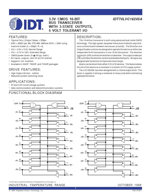
Integrated Device Technology, Inc.DESCRIPTION:The FCT16374T/AT/CT/ET and FCT162374T/AT/CT/ET16-bit edge-triggered D-type registers are built using ad-vanced dual metal CMOS technology. These high-speed,low-power registers are ideal for use as buffer registers fordata synchronization and storage. The Output Enable (xOE)and clock (xCLK) controls are organized to operate eachdevice as two 8-bit registers or one 16-bit register withcommon clock. Flow-through organization of signal pins sim-plifies layout. All inputs are designed with hysteresis forimproved noise margin.The FCT16374T/AT/CT/ET are ideally suited for drivinghigh-capacitance loads and low-impedance backplanes. Theoutput buffers are designed with power off disable capabilityto allow "live insertion" of boards when used as backplanedrivers.The FCT162374T/AT/CT/ET have balanced output drivewith current limiting resistors. This offers low ground bounce,minimal undershoot, and controlled output fall times– reduc-ing the need for external series terminating resistors. TheFCT162374T/AT/CT/ET are plug-in replacements for theFCT16374T/AT/CT/ET and ABT16374 for on-board bus inter-face applications.IDT54/74FCT16374T/AT/CT/ETIDT54/74FCT162374T/AT/CT/ETFAST CMOS 16-BITREGISTER (3-STATE)FUNCTIONAL BLOCK DIAGRAM1O11OE1CLK1D12542 drw 01TO 7 OTHER CHANNELS C D2O12OE2CLK2D1TO 7 OTHER CHANNELS C D2542 drw 01The IDT logo is a registered trademark of Integrated Device Technology, Inc.MILITARY AND INDUSTRIAL TEMPERATURE RANGESFEBRUARY 1997©1997 Integrated Device Technology, Inc.5.8 DSC-2542/91FEATURES:•Common features:–0.5 MICRON CMOS Technology–High-speed, low-power CMOS replacement forABT functions–Typical tSK(o) (Output Skew) < 250ps
–Low input and output leakage ≤1µA (max.)–ESD > 2000V per MIL-STD-883, Method 3015;> 200V using machine model (C = 200pF, R = 0)–Packages include 25 mil pitch SSOP, 19.6 mil pitchTSSOP, 15.7 mil pitch TVSOP and 25 mil pitch Cerpack–Extended commercial range of -40°C to +85°C–VCC = 5V ±10%•Features for FCT16374T/AT/CT/ET:–High drive outputs (-32mA IOH, 64mA IOL)–Power off disable outputs permit “live insertion”–Typical VOLP (Output Ground Bounce) < 1.0V atVCC = 5V, TA = 25°C•Features for FCT162374T/AT/CT/ET:–Balanced Output Drivers:±24mA (commercial),±16mA (military)–Reduced system switching noise–Typical VOLP (Output Ground Bounce) < 0.6V atVCC = 5V,TA = 25°C
For the latest information regarding this part, please contact IDT's web site at http://www.idt.com or fax-on-demand service at (US)1-800-9-IDT-FAX / (International) 408-492-8391.
元器件交易网www.cecb2b.com5.82
IDT54/74FCT16374T/AT/CT/ET, 162374T/AT/CT/ETFAST CMOS 16-BIT REGISTER (3-STATE)MILITARY AND INDUSTRIAL TEMPERATURE RANGES
PIN CONFIGURATIONS
1O1GND1O3VCC1OEGND2O2GNDVCCGND1O21O41O51O61O71O82O12O32O42O52O72O82O62OE1CLK1D11D2GND
1D31D4VCC
1D51D6
1D71D82D12D2
2D32D4VCC
2D5
2D7
2D8
2D6
2CLK
GNDGND
GND
39
29303132333435363738252627284847414243444546401234567891012131415161718192011
21222324
2542 drw 04CERPACK
TOP VIEW
E48-11O1GND1O3VCC1OEGND2O2GNDVCCGND1O21O41O51O61O71O82O12O32O42O52O72O82O62OE1CLK1D11D2
GND
1D31D4
VCC
1D5
1D6
1D7
1D8
2D1
2D2
2D3
2D4
VCC
2D5
2D72D8
2D6
2CLK
GNDGNDGND2542 drw 03
3929303132333435363738252627284847414243444546401234567891012131415161718192011
21222324
SSOP/TSSOP/TVSOPTOP VIEW
SO48-1SO48-2SO48-3
元器件交易网www.cecb2b.comIDT54/74FCT16374T/AT/CT/ET, 162374T/AT/CT/ETFAST CMOS 16-BIT REGISTER (3-STATE)MILITARY AND INDUSTRIAL TEMPERATURE RANGES
5.83PIN DESCRIPTIONFUNCTION TABLE(1)
ABSOLUTE MAXIMUM RATINGS(1)CAPACITANCE (TA = +25°C, f = 1.0MHz)
2542 tbl 012542 tbl 02
NOTE:1. This parameter is measured at characterization but not tested.2542 lnk 04
SymbolParameter(1)ConditionsTyp.Max.UnitCINInputCapacitanceVIN = 0V3.56.0pF
CI/OI/OCapacitanceVOUT = 0V3.58.0pF
Pin NamesDescriptionxDxData InputsxCLKClock InputsxOx3-State Outputs.xOE 3-State Output Enable Input (Active LOW)
InputsOutputsFunctionxDxxCLKxOExOxHi-ZXLHZXHHZLoadL↑LLRegisterH↑LHL↑HZH↑HZNOTE:1.H = HIGH Voltage LevelL = LOW Voltage LevelX = Don’t CareZ = High Impedance↑ = LOW-to-HIGH Transition
SymbolDescriptionMax.UnitVTERM
(2)
Terminal Voltage with Respect to
GND–0.5 to +7.0V
VTERM(3)Terminal Voltage with Respect toGND–0.5 toVCC +0.5 VTSTGStorage Temperature–65 to +150°CIOUTDC Output Current–60 to +120 mANOTES:1.Stresses greater than those listed under ABSOLUTE MAXIMUM RAT-INGS may cause permanent damage to the device. This is a stress ratingonly and functional operation of the device at these or any other conditionsabove those indicated in the operational sections of this specification isnot implied. Exposure to absolute maximum rating conditions forextended periods may affect reliability.2.All device terminals except FCT162XXXT Output and I/O terminals.3.Output and I/O terminals for FCT162XXXT.