IDT54FCT244SOB中文资料
- 格式:pdf
- 大小:160.18 KB
- 文档页数:8
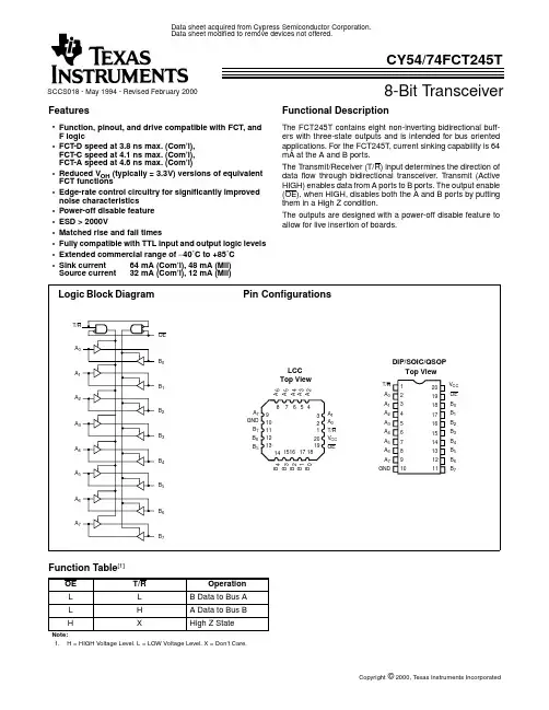
MILITARY AND COMMERCIAL TEMPERATURE RANGESMAY 1992•IDT54/74FCT240/241/244/540/541 equivalent to FAST TMspeed and drive•IDT54/74FCT240A/241A/244A/540A/541A 25% faster than FAST•IDT54/74FCT240C/241C/244C/540C/541C up to 55%faster than FAST•I OL = 64mA (commercial) and 48mA (military)•CMOS power levels (1mW typ. static)•Product available in Radiation Tolerant and Radiation Enhanced versions•Military product compliant to MIL-STD-883, Class B •Meets or exceeds JEDEC Standard 18 specificationsFUNCTIONAL BLOCK DIAGRAMS2529 cnv* 01–03OE ADA 0OB 0DA 1OB 1DA 2OB 2DA 3OB 3OE BOA 0DB 0OA 1DB 1DB 2DB 3OA 23IDT54/74FCT240OE ADA 0OB 0DA 1OB 1DA 2OB 2DA 3OB 3OE B *OA 0DB 0OA 1DB 1DB 2DB 3OA 2OA 3IDT54/74FCT241/244*OE B B for 244OE A D 0OE BO 0*D 1D 2D 3D 4D 5D 6D 7O 1*O 2*O 3*O 4*O 5*O 6*O 7*IDT54/74FCT540/541*Logic diagram shown for 'FCT540.'FCT541 is the non-inverting option.The IDT octal buffer/line drivers are built using an advanced dual metal CMOS technology. The IDT54/74FCT240/A/C,IDT54/74FCT241/A/C and IDT54/74FCT244/A/C are designed to be employed as memory and address drivers, clock drivers and bus-oriented transmitter/receivers which provide improved board density.The IDT54/74FCT540/A/C and IDT54/74FCT541/A/C are similar in function to the IDT54/74FCT240/A/C and IDT54/74FCT244/A/C, respectively, except that the inputs and out-puts are on opposite sides of the package. This pinout arrangement makes these devices especially useful as output ports for microprocessors and as backplane drivers, allowing ease of layout and greater board density.2606 dwg 01–03The IDT logo is a registered trademark of Integrated Device Technology, Inc.FAST is a trademark of National Semiconductor Co.PIN CONFIGURATIONSIDT54/74FCT2402529 cnv* 04–092606 cnv* 04–09IDT54/74FCT241/244IDT54/74FCT540/541*OE B for 241, OE B for 244*O X for 540, O Xfor 541OE A DA 0OB 0DA 1OB 1DA 2OB 2DA 3OB 3GNDOE B *OA 0DB 0OA 1DB 1DB 2DB 3OA 2OA 3V CC DIP/SOIC/CERPACKTOP VIEWOA 0DB 0OA 1DB 1OA 2*O B 3G N D D B 3O A 3D B 2LCC TOP VIEWOE A DA 0OB 0DA 1OB 1DA 2OB 2DA 3OB 3GNDOE B OA 0DB 0OA 1DB 1DB 2DB 323V CC DIP/SOIC/CERPACKTOP VIEWOA 0DB 0OA 1DB 1OA 2O B 3G N DD B 3O A 3D B 2LCC TOP VIEWOE A D 0D 1D 2D 3D 4D 5D 6D 7GNDOE B O 0*O 1*O 2*O 3*O 5*O 7*O 4*O 6*V CCDIP/SOIC/CERPACKTOP VIEWO 0*G N D LCC TOP VIEWO 1*O 2*O 3*O 4*O 7*O 6*O 5*D 7PIN DESCRIPTIONFUNCTION TABLE2606 tbl 041. OE B for 241 only.1.H = High Voltage Level X = Don’t CareL = Low Voltage Level Z = High Impedance 2.OE B for 241 only.(1)2606 tbl 011.Stresses greater than those listed under ABSOLUTE MAXIMUM RATINGS may cause permanent damage to the device. This is a stress rating only and functional operation of the device at these or any other conditions above those indicated in the operational sections of this specification is not implied. Exposure to absolute maximum rating conditions for extended periods may affect reliability. No terminal voltage may exceed V CC by +0.5V unless otherwise noted.2.Input and V CC terminals only.3.Outputs and I/O terminals only.DC ELECTRICAL CHARACTERISTICS OVER OPERATING RANGEFollowing Conditions Apply Unless Otherwise Specified: V LC = 0.2V; V HC = V CC – 0.2VA CC A CCNOTES:2606 tbl 031.For conditions shown as Max. or Min., use appropriate value specified under Electrical Characteristics for the applicable device type.2.Typical values are at V CC = 5.0V, +25°C ambient and maximum loading.3.Not more than one output should be shorted at one time. Duration of the short circuit test should not exceed one second.4.This parameter is guaranteed but not tested.POWER SUPPLY CHARACTERISTICS2606 tbl 061.For conditions shown as Max. or Min., use appropriate value specified under Electrical Characteristics for the applicable device type.2.Typical values are at V CC = 5.0V, +25°C ambient.3.Per TTL driven input (V IN = 3.4V); all other inputs at V CC or GND.4.This parameter is not directly testable, but is derived for use in Total Power Supply Calculations.5.Values for these conditions are examples of the I CC formula. These limits are guaranteed but not tested.6.I C = I QUIESCENT + I INPUTS + I DYNAMICI C = I CC + ∆I CC D H N T + I CCD (f CP/2 + f i N i)I CC = Quiescent Current∆I CC = Power Supply Current for a TTL High Input (V IN = 3.4V)D H = Duty Cycle for TTL Inputs HighN T = Number of TTL Inputs at D HI CCD = Dynamic Current Caused by an Input Transition Pair (HLH or LHL)f CP = Clock Frequency for Register Devices (Zero for Non-Register Devices)f i = Input FrequencyN i = Number of Inputs at f iAll currents are in milliamps and all frequencies are in megahertz.SWITCHING CHARACTERISTICS OVER OPERATING RANGE FOR FCT240(1,2)2606 tbl 07SWITCHING CHARACTERISTICS OVER OPERATING RANGE FOR FCT241 AND FCT244(1,2)(1,2)2606 tbl 08 SWITCHING CHARACTERISTICS OVER OPERATING RANGE FOR FCT540 AND FCT541(1,2)1.See test circuit and waveforms.2.Minimum limits are guaranteed but not tested on Propagation Delays.TEST CIRCUITS AND WAVEFORMS TEST CIRCUITS FOR ALL OUTPUTSENABLE AND DISABLE TIMESPROPAGATION DELAYSET-UP, HOLD AND RELEASE TIMESPULSE WIDTHDATA INPUTTIMING INPUTPRESET CLEAR ETC.PRESET CLEARCLOCK ENABLEETC.3V 1.5V 0V 3V 1.5V 0V 3V 1.5V 0V 3V 1.5V 0V7.0VSAME PHASE INPUT TRANSITION3V 1.5V0V 1.5V V OH V OL OUTPUTOPPOSITE PHASE INPUT TRANSITIONV OL V OH 3V 1.5V 0VENABLEDISABLENOTES 2606 drw 101.Diagram shown for input Control Enable-LOW and input ControlDisable-HIGH.2.Pulse Generator for All Pulses: Rate ≤ 1.0 MHz; Z O ≤ 50Ω; t F ≤ 2.5ns;t R ≤ 2.5ns.SWITCH POSITIONTest Switch Open Drain Disable Low Closed Enable Low All Other TestsOpenDEFINITIONS:2606 tbl 10C L =Load capacitance: includes jig and probe capacitance.R T =Termination resistance: should be equal to Z OUT of the PulseGenerator.ORDERING INFORMATION2606 cnv* 15IDT XX Temp. Range XXXX Device TypeXPackageXProcessCommercialMIL-STD-883, Class B Plastic DIP CERDIPSmall Outline ICLeadless Chip Carrier CERPACKInverting Octal Buffer/Line DriverNon-Inverting Octal Buffer/Line Driver Non-Inverting Octal Buffer/Line Driver Inverting Octal Buffer/Line DriverNon-Inverting Octal Buffer/Line Driver Fast Inverting Octal Buffer/Line DriverFast Non-Inverting Octal Buffer/Line Driver Fast Non-Inverting Octal Buffer/Line Driver Fast Inverting Octal Buffer/Line DriverFast Non-Inverting Octal Buffer/Line Driver Super Fast Inverting Octal Buffer/Line DriverSuper Fast Non-Inverting Octal Buffer/Line Driver Super Fast Non-Inverting Octal Buffer/Line Driver Super Fast Inverting Octal Buffer/Line DriverSuper Fast Non-Inverting Octal Buffer/Line Driver –55°C to +125°C 0°C to +70°CFCT。