全自动电脑洗车机新款大全-文档资料
- 格式:ppt
- 大小:2.48 MB
- 文档页数:10
全自动洗车机安全操作规程范文第一章总则第一条为了加强全自动洗车机的安全管理和操作规范,确保使用过程中的人身安全和设备的正常运行,制定本规程。
第二条本规程适用于全自动洗车机的操作人员和维护人员,在使用和维护全自动洗车机时必须遵守本规程。
第三条全自动洗车机的操作人员和维护人员必须经过相应的培训,取得相应的操作证书或维修证书后方可操作和维护全自动洗车机。
第四条全自动洗车机的操作人员和维护人员必须认真遵守本规程,严禁违反安全规定进行操作和维护。
第五条全自动洗车机的操作人员和维护人员必须保持良好的职业操守,严禁在操作和维护过程中饮酒、吸烟等行为。
第二章操作规范第六条在操作全自动洗车机之前,操作人员必须先检查全自动洗车机的工作状态是否正常,包括水源、电源、气源等是否连通正常。
第七条操作人员在操作全自动洗车机时必须佩戴相关的安全防护装备,包括护目镜、防护手套等。
第八条操作人员在使用全自动洗车机前,必须先将车辆内的重要物品清理干净,以免遗失或损坏。
第九条操作人员必须按照全自动洗车机的操作说明进行操作,不能随意更改设备的运行参数。
第十条在操作全自动洗车机时,操作人员必须保持冷静,严禁恶意破坏设备或进行危险行为。
第十一条操作人员在操作全自动洗车机时,必须保持机器周围的安全距离,切勿将身体或衣物靠近设备的移动部件。
第十二条操作人员在操作过程中,严禁随意触摸设备的内部部件,避免发生触电危险。
第十三条在操作全自动洗车机时,如果发现设备出现异常,如异响、冒烟等情况,必须立即停止操作,并及时向维护人员报告。
第十四条在操作全自动洗车机时,操作人员必须注意设备四周的安全环境,确保没有人员靠近或越过设备的工作区域。
第十五条操作人员在操作全自动洗车机时,必须严格按照操作流程进行操作,不得随意中断或跳过操作步骤。
第十六条操作人员在操作全自动洗车机时,必须保持设备的清洁和整洁,及时清理设备表面的灰尘和杂物。
第三章维护规范第十七条维护人员在进行维护工作前,必须先断开全自动洗车机的电源,并进行相应的锁定和标识。
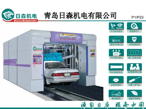
青岛日森机电有限公司P1/P23P2/P23青岛日森机电有限公司于2010年创立,前身是青岛益丰泽实业有限公司洗车机事业部。
2009年日本MK 精工株式会社和青岛益丰泽实业有限公司正式达成了紧密合作生产洗车机的协议。
2010年1月1日MK 精工开始向日森机电提供技术资料、生产和检测标准、派遣技术工程师、供应核心零部件,全力协助日森机电与日本同步生产可搭载CPU 的最先进的洗车机。
搭载了CPU 的洗车机不但能完成高精度的洗车流程,并且附带了LED 画面以及声音操作向导、细密的数据管理、洗车打印机等附属功能。
MK 精工协助日森机电有限公司培养出的技术力量有力的保证了产品的品质,使之迅速成为畅销商品。
不仅如此,日森洗车机投放到市场以来,以领先业内其他厂家15年以上的技术能力、产品品质和操作安全性而备受消费者的好评,现在已成为该行业高起点的技术创新型公司。
青岛日森机电有限公司位于青岛经济技术开发区海尔工业园内,占地40亩,厂房10000多平方米,已投入使用生产面积4000多平方米,公司目前已拥有包括15名高级技术人员在内的60多人的队伍。
在此基础上,青岛日森机电有限公司应消费者的强烈要求,从2010年3月起连续推出了一系列代表高科技水平、高性价比的洗车设备,有效满足了当今消费者要求省人工、高效、节水、环保的需要。
企业简介企业认证P3/P26企业证书P4/P26P5/P23RisenseDescription of the contents* 源自日本——35年的洗车机制造专家*服务中国——为您提供综合解决方案日森全自动电脑洗车机颠覆中国传统洗车模式日森全自动隧道式电脑洗车机性能特点技术参数配置说明产品优势Performance characteristicsTechnical parametersConfiguration instructionsProduct advantages隧道式全自动电脑洗车机性能特点P6/P23●作业流程:机器不动,利用轨道拖动汽车移动进行清洗,自动完成整个清洗吹风过程,可以连续洗车●全程语音提示●经营管理功能●多种洗车方式组合●工作效率:标准速(33台/h)高速(50台/h)●超低能耗:耗水量(90L/台)耗电量(0.28kwh/台)P7/P23隧道式全自动电脑洗车机性能特点●日森全自动隧道式洗车机使用同步轮胎导正和入车辅助广角镜,更方便的将洗车导入洗车机进行清洗。
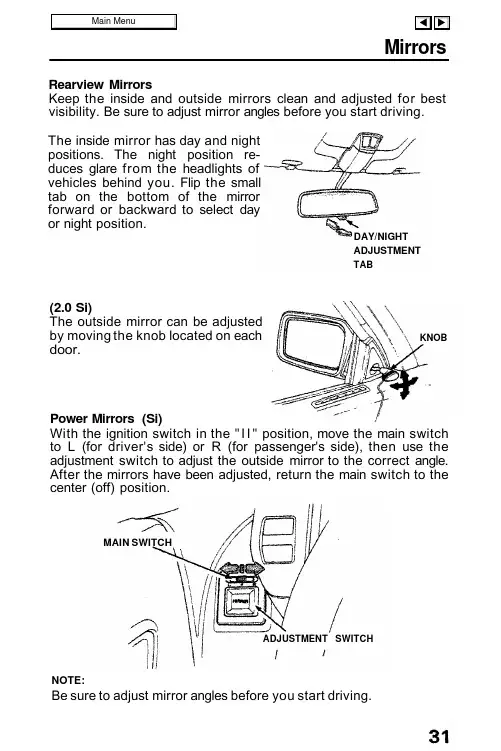
MirrorsRearview MirrorsKeep the inside and outside mirrors clean and adjusted for best visibility. Be sure to adjust mirror angles before you start driving.The inside mirror has day and night positions. The night position re-duces glare from the headlights of vehicles behind you. Flip the small tab on the bottom of the mirror forward or backward to select day or night position.(2.0 Si)The outside mirror can be adjusted by moving the knob located on each door.Power Mirrors (Si)With the ignition switch in the "I I " position, move the main switch to L (for driver's side) or R (for passenger's side), then use the adjustment switch to adjust the outside mirror to the correct angle.After the mirrors have been adjusted, return the main switch to the center (off) position.NOTE:Be sure to adjust mirror angles before you start driving.DAY/NIGHT ADJUSTMENT TABKNOBADJUSTMENT SWITCHMAIN SWITCHRIGHT TURNTurn Signals Push the turn signal lever down to signal a left turn, and up for a right turn. The indicator and appropriate signal lights will blink. The lever willreturn automatically to its original position when the steering wheel is returned to straight ahead.For lane changing, you can signal by pushing the lever part way up or down (to the first stop) and holding it there; the lever will return to its original position when you release it. If either turn signal indicator lights up but does not blink, blinks faster than usual or does not light up at all, check for a burned out bulb or fuse.LEFT TURNHeadlightsTurn the light switch to the first position ( ) for taillights, side marker lights, position lights, license plate lights, and instrument panel lights. Turn to the second position ( ) to raise and add the headlights.When the switch is returned from the second to the first position,the headlights will go off but will not retract; they retract when the light switch is turned to OFF.If the driver's door is opened when the light switch is turned to either "o n " position, a chime will sound to remind you to turn off your lights.If you wish to raise or retract the headlights when the light switch is off (to use them as a passing signal for example), you may do so by pushing the headlight motor switch, located on the left side of the instrument panel; see page 34 for instructions on its use.CAUTION:Do not operate the headlight switch or headlight motor switch if anyone's hands are near the headlights.LightsFIRST POSITIONTurn SECONDPOSITION FIRST STOPFIRSTSTOPNOTE:If the headlight motor switch is pushed in, the headlights will notretract when the light switch is turned off.If the headlights neither rise nor retract, they can be operated manually; see page 127 .If you're driving in wet snow or freezing rain, keep the headlights in the raised position by using the headlight motor switch; this way/they can still be used if the headlight motors freeze.If the headlights have frozen in either the up or down position,remove all ice before operating the headlight motors.High Beam/Low Beam SwitchThe headlights may be switched between low beam and high beam by pulling the turn signal lever towards you. The blue high beam indicator light will be on when the high beam is on.Headlight FlasherTo flash the headlights, first raise them with the headlight motor switch, then lightly pull and release the light switch.CAUTION:Do not operate the headlight switch or headlight motor switch if anyone's hands are near the headlights.(cont'd)Pull and releaseLights (cont'd)Headlight Motor SwitchPush the headlight motor switch to raise and/or retract the headlights while they are off. The headlights should be raised in this manner whenever you intend to use them as a passing signal, or if there is a possibility of the headlight motors freezing.CAUTION:Do not operate the headlight motor switch if anyone's hands are near the headlights.NOTE:The headlight motor switch will not retract the headlights if they are already turned on.If the headlights neither rise nor retract, they can be operated manually; see page 127 .If the headlights have frozen in either the up or down position,remove all ice before operating the headlight motors.Fog Lamp Switch (Si)Push the switch to operate the fog lamps.The fog lamps will light only when the headlights are on at low beam.PushPushHazard Warning SystemThis system should be used only when your car is stopped under emergency or hazardous conditions.To activate, push the hazard warn-ing switch ( ). The front and rear turn signals will blink simultaneously and both indicator lights will flash.Push the switch ( ) again to turn the system off.Panel Brightness ControlWhen the light switch is in either of the two "ON" positions, the intensi-ty of the instrument lights can be adjusted by turning the panel bright-ness control dial.Interior LightThe interior light has a three posi-tion switch. The light is off all the time in the OFF position. In the mid-dle position, it goes on only when a door is opened. In the ON position, it is on all the time.(cont'd)DOORACTIVATEDOFFONBright DarkPushLights (cont'd)Keyhole Light (Si)When the driver's door handle ispulled, the keyhole light goes on.This is convenient for finding thekeyhole location in the dark. Thelight goes out after several seconds.Ignition Switch Light (Si)This light will illuminate the switchfor several seconds after the driver'sdoor is closed.Trunk LightThe trunk compartment light goeson when the trunk lid is opened.TRUNKLIGHTCruise ControlCruise ControlThe Cruise Control system allows you to set and automatically maintain any speed above 30 mph (45 km/h) without keeping your foot on the accelerator. As its name implies, it is meant for cruising on straight, uncongested highways or freeways. It is not recommended to be used in traffic, on winding roads or in bad weather conditions where the driver should have total control.To Set the Cruise Control:Push the CRUISE CONTROL master switch on the dash; the indicator fight will come on.Accelerate to the desired speed,then push and release the SET switch on the steering wheel. The Cruise Control light on the instru-ment panel will come on.The speed you were going when you released the SET switch is the speed the Cruise Control will hold. You can then "fine tune" the set speed by briefly holding and releasing the SET switch to decrease it a few mph or pushing the RESUME switch to slightly increase it.RESUME SWITCH SET SWITCHTo Cancel the Cruise Control:Simply push the CRUISE CONTROL master switch and the indicator light will go off (this also erases the memory of the set speed).If you must temporarily disengage the system (but you wish to retain the memory of the set speed): tap the brake pedal, or the clutch pedal (manual tranmission) or move the automatic trans-mission shift lever to N (Neutral). If you are still going above 30 mph (45 km/h), you can return to the set speed by simply pushing the RESUME switch. If the car has decelerated below approximately 30 mph (45 km/h),you can return to the set speed by using the ac-celerator conventionally until your speed is above 30 mph (45 km/h)and then pushing the RESUME switch.(cont'd)MASTER SWITCHPushCruise Control (cont'd)To Change the Set Speed:To a faster speed — For gradual acceleration with your foot off the accelerator, push and hold the RESUME switch until you reach the desired speed; release the switch and the system's memory will be re-programmed to the new speed.For faster acceleration, push the accelerator until you reach the desired speed, then push and release the SET switch to re-program the system.To a slower speed — push and hold the SET switch and the car will coast; when you reach the desired slower speed, release the switch and the system will be re-programmed.For temporary acceleration above the set speed, such as for passing, use the accelerator pedal conventionally. When you want to return to the set speed, take your foot off the accelerator and coast without applying the brakes.The Cruise Control automates the function of the accelerator pedal to maintain your car at a constant speed. This can be a convenience on long trips, but it can also be a danger if there are many other cars on the road or if the road is unfamiliar. Pay strict attention to the responsibility of driving whenever using the Cruise Control.CAUTION:Because the Cruise Control directly activates the accelerator pedal, don't rest your foot under the pedal when the Cruise Control is on; it may pull the pedal down onto your foot.NOTE:With Cruise Control on, your speed will still vary slightly,particularly when going up or down hills.Do not drive with your foot on the brake or clutch pedal (manualtransmission), as this will cause the Cruise Control to disengage.。
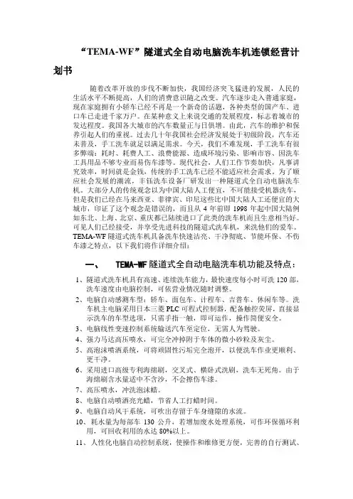
“TEMA-WF”隧道式全自动电脑洗车机连锁经营计划书随着改革开放的步伐不断加快,我国经济突飞猛进的发展,人民的生活水平不断提高,人们的消费意识随之改变。
汽车逐步走入普通家庭,现在家庭拥有小轿车已经不再是一个新奇的话题,各种类型的国产车、进口车已走进千家万户。
在某种意义上来说交通的发展程度,标志着城市的发达程度。
我国各大城市的汽车数量正与日俱增。
由此,汽车的维护和保养引起人们的重视。
过去几十年我国社会经济发展处于初级阶段,汽车还未普及,手工洗车就足以满足需求。
今天,我们不难发现,手工洗车有很多弊端:耗时、耗费人工、浪费能源、造成环境污染、影响市容、因洗车工具用品不够专业而易伤车漆等。
现代社会,人们工作节奏加快,凡事讲究效率,时间就是金钱,传统的手工洗车已经不能适应社会需求。
为了顺应社会发展的潮流,丰钰洗车设备厂研发出一种隧道式全自动电脑洗车机。
大部分人的传统观念以为中国大陆人工便宜,不可能接受机器洗车,但是我们已经在马来西亚、菲律宾、印尼这些比中国大陆人工还便宜的大城市,印证了这个观念是错误的,而且从4年前即1998年起中国大陆例如东北、上海、北京、重庆都已陆续进口了此类的洗车机而且生意相当好。
可见人们已经接受,并享受先进科技的隧道式洗车机,来洗他们的爱车。
TEMA-WF隧道式洗车机具备洗车快速洁亮、干净彻底、节能环保、不伤车漆之特点,以下我们将作详细介绍:一、TEMA-WF隧道式全自动电脑洗车机功能及特点:1、隧道式洗车机具有高速、连续洗车能力,最快速度每小时可洗120部,洗车速度由电脑控制,可依营业情况随时调整。
2、电脑自动感测车型:轿车、面包车、计程车、吉普车、休闲车等。
洗车机主电脑采用日本三菱PLC可程式控制器,配备触控荧屏,直接显示洗车的车型选项,只需手指一触,即可运作,操作简便安全。
3、电脑线性变速控制系统输送汽车至定位,无需人为驾驶。
4、强力马达高压喷水,可完全冲掉附于车体的微小砂粒及灰尘。
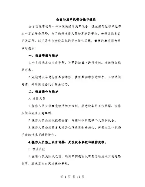
全自动洗车机安全操作规程全自动洗车机是一种方便快捷的洗车设备,但在使用过程中也存在一定的安全风险。
为了确保操作人员和车辆的安全,并保证设备的正常运行,以下是全自动洗车机的安全操作规程,重要的事项用大写字母表示:一、设备安装与维护1. 全自动洗车机应在平整、牢固的地面上进行安装。
确保设备稳固可靠。
2. 定期对设备进行保养和维修,在保养和维修过程中,必须关闭电源,并确保设备处于安全状态。
二、设备操作与维护A. 操作人员1. 操作人员必须事先接受相关培训,熟悉设备的工作原理、操作步骤和安全注意事项。
2. 操作人员必须佩戴安全帽、耳塞和护目镜等个人防护设备。
3. 操作人员必须具备良好的心理素质和责任心,严禁在工作状态不佳的情况下进行操作。
4. 操作人员禁止私自调整、更改设备参数和操作流程。
B. 预洗阶段1. 在进行预洗阶段之前,确保车辆表面没有易燃物质或其他危险物质,避免发生火灾或意外事故。
2. 在预洗阶段,严禁将手部或其他身体部位放置在洗车喷枪或喷嘴附近。
C. 洗涤阶段1. 在洗涤阶段进行前,确认车窗全部关闭,避免进水造成车内损坏。
2. 在洗涤阶段,严禁将身体部位伸入洗车机内部,以免造成伤害。
D. 烘干阶段1. 在烘干阶段中,确保车辆停在指定位置并紧密固定,防止烘干风力对车辆造成伤害。
2. 在烘干阶段,操作人员应注意观察烘干系统的运行情况,确保其正常工作。
E. 紧急情况处理1. 在全自动洗车机发生故障或其他紧急情况时,必须立即停止设备运行,并通知维修人员进行检修。
2. 在出现火灾、漏电、短路等危险情况时,及时切断电源。
三、设备周边环境安全A. 设备周边区域安全1. 在设备周边建立明确的安全区域,禁止非操作人员靠近。
2. 设备周边应设置明显的警示标志,警示非操作人员不得靠近设备。
B. 防火安全1. 在设备周边应设置灭火器,并定期维护和检查,以确保灭火器的有效性。
2. 确保设备周边没有易燃物质的积存,避免火灾发生。
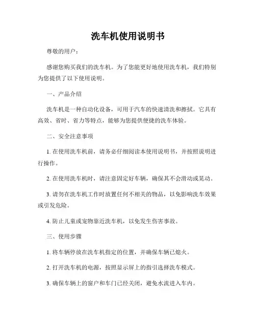
洗车机使用说明书尊敬的用户:感谢您购买我们的洗车机。
为了您能更好地使用洗车机,我们特别为您提供了以下使用说明。
一、产品介绍洗车机是一种自动化设备,可用于汽车的快速清洗和擦拭。
它具有高效、省时、省力等特点,能够为您提供便捷的洗车体验。
二、安全注意事项1. 在使用洗车机前,请务必仔细阅读本使用说明书,并按照说明进行操作。
2. 在使用洗车机时,请注意固定好车辆,确保其不会滑动或晃动。
3. 请勿在洗车机工作时放置任何不相关的物品,以免影响洗车效果或引发危险。
4. 防止儿童或宠物靠近洗车机,以免发生伤害事故。
三、使用步骤1. 将车辆停放在洗车机指定的位置,并确保车辆已熄火。
2. 打开洗车机的电源,按照显示屏上的指引选择洗车模式。
3. 确保车辆上的窗户和车门已经关闭,避免水流进入车内。
4. 按下开始按钮,洗车机将开始工作。
您可以根据需要选择自动模式或者手动模式。
5. 在洗车过程中,请注意观察洗车机的状态,以确保其正常运行。
6. 洗车结束后,关闭洗车机的电源,并等待车身完全干燥后移开您的车辆。
四、常见问题解答1. 洗车机无法启动怎么办?答:请检查电源是否连接稳固,是否有电源输入。
如有异常,请联系售后服务中心进行维修。
2. 洗车模式无法选择怎么办?答:请确认洗车机是否处于正常工作状态,如果问题仍然存在,请联系售后服务中心获得帮助。
3. 洗车机洗车效果不佳怎么办?答:首先,请检查洗车机的喷水口是否被堵塞。
如果是,清洁喷水口后再次尝试。
如果问题仍然存在,请联系售后服务中心解决。
五、保养维护1. 每次使用后,请及时清洁洗车机的喷水口和滚轮,以确保其正常工作。
2. 定期检查洗车机的电源线和接线是否正常,并避免使用受损的电源线。
3. 如遇到任何异常情况,请关闭电源,并联系售后服务中心进行维修。
六、注意事项1. 请勿将手伸入洗车机内部以免发生危险。
2. 在使用洗车机时,请勿将喷水口对准人体或动物,以免造成伤害。
3. 请勿在洗车机工作时使用任何化学清洁剂或溶剂,以免损坏洗车机。


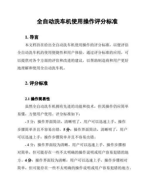
全自动洗车机使用操作评分标准1. 导言本文档旨在给出全自动洗车机使用操作的评分标准,以便评估全自动洗车机的使用便捷性和用户体验。
通过评分标准的应用,可以提供对各个方面的评估和改进的建议,以帮助制造商和用户更好地理解和使用全自动洗车机。
2. 评分标准2.1 操作简易性虽然全自动洗车机拥有先进的功能和技术,但其操作仍应简单易懂,方便用户使用。
评分标准如下:- 5分:操作界面简洁,清晰明了,用户可以迅速上手,操作步骤简单并且不容易出错。
5分:操作界面简洁,清晰明了,用户可以迅速上手,操作步骤简单并且不容易出错。
- 4分:操作界面较为清晰,用户可以迅速上手,操作步骤相对简单,但可能存在一些不太明确的操作说明或用户容易犯错的地方。
4分:操作界面较为清晰,用户可以迅速上手,操作步骤相对简单,但可能存在一些不太明确的操作说明或用户容易犯错的地方。
- 3分:操作界面一般,用户可能需要一些时间来适应,操作步骤较为繁琐,但仍可接受。
3分:操作界面一般,用户可能需要一些时间来适应,操作步骤较为繁琐,但仍可接受。
- 2分:操作界面较为复杂,用户需要较长的时间来理解和操作,存在明显的操作难度。
2分:操作界面较为复杂,用户需要较长的时间来理解和操作,存在明显的操作难度。
- 1分:操作界面混乱,操作步骤复杂,用户几乎无法使用。
1分:操作界面混乱,操作步骤复杂,用户几乎无法使用。
2.2 功能完整性全自动洗车机应提供完整的功能,以满足用户的需求。
评分标准如下:- 5分:全自动洗车机提供了完整的功能,包括基本清洗、烘干、打蜡等功能,用户无需额外操作。
5分:全自动洗车机提供了完整的功能,包括基本清洗、烘干、打蜡等功能,用户无需额外操作。
- 4分:全自动洗车机提供了大部分功能,但可能缺少一些高级功能或特殊清洗模式。
4分:全自动洗车机提供了大部分功能,但可能缺少一些高级功能或特殊清洗模式。
- 3分:全自动洗车机提供了基本的清洗功能,但缺少一些常用的功能或特殊清洗模式。
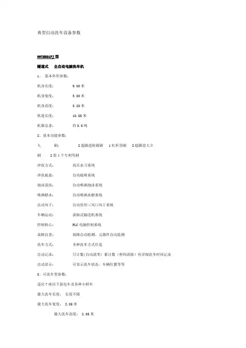
典型自动洗车设备参数09TSD21FJ型隧道式全自动电脑洗车机1、基本外形参数:机身长度: 9.00米机身宽度: 3.80米机身高度: 3.20米轨道长度: 10.55米机器总重:约3.5吨2、基本功能参数:九刷:2超跟进轮毂刷 1杠杆顶刷 2超跟进大立刷 2组4个专利弯刷冲洗方式:高压水刀系统冲洗底盘:自动底喷系统泡沫清洗:自动喷洒泡沫系统喷洒蜡水:自动喷洒水蜡系统自动风干:自动仿形三风口风干系统车辆运动:滚轴式输送机系统控制核心: PLC电脑控制系统故障自查:故障自动检测、元器件自动监测洗车方式:多种洗车方式任选自动记录:日计数(自动清零) 累计数(密码清除)有详细洗车时间记录自动显示:可显示洗车状态、车辆位置等等3、可洗车型参数:适应7座以下面包车及各种小轿车最大洗车长度:长度不限最大洗车宽度: 2.05米最大洗车高度: 2.05米4、基本配置:外型:玻璃钢一次成型双侧门头及外饰板(中国红)防水:机件防锈处理电气元件选用高防水等级机架:热镀锌C型钢机架操作面板:按钮+7吋真彩色触摸屏5、用水、用电参数:用电种类: 380V三相动力电装机功率: 18KW耗电量: 0.3度/辆耗水量:加水循环设备 12升/辆无水循环设备60升/辆6、洗车速度参数:单车洗车时间: 2分钟/辆每小时洗车量: 30辆7、电子触摸屏界面、开关板及说明书:可以根据不同国家和地区提供不同语言版本最新售价:25万元大巴士洗车机技术参数及功能型号 04TSD35型设备机体规格长8800mm宽5600mm高4200mm 清洗车辆类型大客车、中巴车最大洗车规格3500mm(H)2600mm(W)洗车速度30——50辆/小时耗水量250升设备电器容量15KW操作方式自动操作、手动控制操作洗涤方式选择普通水洗、清洗剂洗洗涤刷条丽柔耐磨刷条四根无刷自动洗车机外形参数:机身长度:1.9米机身宽度:3.10米机身高度:2.85米轨道长度:10米轨道宽度:2.9米机器总重:约1.5吨功能参数:冲洗方式:高压水刀系统冲洗底盘:自动底喷系统泡沫清洗:喷洒泡沫可洗车型参数:适应7座以下面包车及各种小轿车最大洗车长度:5.00米最大洗车宽度:2.00米最大洗车高度:2.00米基本配置:防水:机件防锈处理电气元件选用高防水等级机架:热镀锌板柜式结构操作面板:按钮用水、用电参数:用电种类:380V三相动力电装机功率:6KW耗电量:0.1度/辆耗水量:加水循环设备30升/辆无水循环设备100升/辆速度参数:单车洗车时间:3-5分钟/辆每小时洗车量:20-25辆显示屏界面、开关板:可以根据不同国家和地区提供不同语言版。

清洗机使用说明书最终版pdf1清洗机使用说明书自动清洗机说明书All rightsreserved未经许可,不得翻印Page 1 of16自动清洗机使用说明书纳金Nanometals使用说明书Operrating InstructionsNJ-QXJ-001 自动清洗机(工业用途)Automatic Cleaning Machine (Industial)感谢使用纳金科技清洗机产品在安装、使用与维修前请仔细阅读本手册以期发挥最佳性能并维护安全清洗机使用说明书自动清洗机说明书All rightsreserved未经许可,不得翻印Page 2 of16自动清洗机使用说明书目录●安全注意事项●重要信息●清洗机主要规格参数●零部件名称和附图说明●显示屏附图说明及含义∙主界面∙手动画面∙参数设置●使用步骤∙触膜屏的设置∙锥形瓶的固定∙启动程序∙其它方面●维护及保养说明书All rights reserved未经许可,不得翻印Page 3 of16自动清洗机使用说明书安全注意事项●启动机器前,必须穿实验服,戴手套,带口罩,带上护目眼镜(否则可能会导致轻微中毒,灼伤皮肤和眼睛)●禁止将头伸入,通风橱里的机器中,以免发生意外(否则可能会导致轻微中毒,或者头部会被夹伤)●启动机器前,必须将通风橱的开关打开(否则可能会导致有害气体不能够及时排出,人体接触会轻微腐蚀和中毒)●请把放锥形瓶的槽格都装满,装满后务必把固定盖板合上(否则可能会导致部分强酸强碱,溅出水槽以外,腐蚀部分零件,机器寿命变短)●严禁不戴手套直接用手触碰固定盖板(否则可能会导致触碰的部位被轻微腐蚀)●在机器运行时严禁将通风橱中的开关断开(否则可能会导致清洗中的有害气体不能及时排出实验室外)●在机器运行时,出现紧急情况,立即断开电源(否则可能会导致冒烟、起火、触电或腐蚀)说明书All rights reserved未经许可,不得翻印Page 4 of16自动清洗机使用说明书若工作中出现以下异常或故障∙喷头结构没有正常的上或下移动∙长形喷头没有正常的喷出液体∙旋转放置机构没有正常的左右翻转∙排液时电磁阀没有按照设定次序打开排液管∙电磁阀出现异常,不能止水或同时打开∙光电感应器异常亮起∙存在其它异常情况或故障请立即按掉显示屏上的“停止”开关,上述任一情况若依然存在异常则立即按掉总电源,并与客户咨询服务中心联系进行检查和修理。
Product features• AEC-Q200 qualified•0603 (1608 metric) compact design utilizes less board space• Rapid interruption of excessive current • Compatible with reflow and wave solder • Rugged ceramic and glass construction • Excellent environmental integrity • One time positive disconnect • High breaking capacity up to 63 V •Moisture sensitivity level (MSL) :1ApplicationsAutomotive• Battery management systems (BMS)• Central body control module • Doors, window lift and seat control • Digital instrument cluster• In-vehicle infotainment (IVI) and navigation •Electric pumps, motor control and auxiliaries •Powertrain control module (PCU)/engine control unit (ECU)•T ransmission control unit (TCU)Agency information• UL Recognized File: File E19180•AEC-Q200 qualifedEnvironmental compliance• Values less than 1 A are not lead freeOrdering•Use ordering codes (see page 3 for details)Packaging sufixes•-TR (5,000 parts in paper tape on a 178 mm (7”) reel)CC06FAAutomotive grade fast-acting chip fusePb HALOGENHFFREE2Technical Data 11003Effective September 2021CC06FAAutomotive grade fast-acting chip fuse/electronicsElectrical characteristicsAmp Rating% of Amp RatingOpeni ng Ti me500 mA – 1.5 A 100% 4 hours minimum 500 mA – 1.5 A200%60 seconds maximumProduct specificationsPart Number 5Current rating (A)Voltage rating (Vdc)Interrupting rating¹(A)Typical DC cold resistance² (Ω)Typical pre-arcing³I²t (A 2s)Typical voltage drop (V)PartmarkingCC06FA500mA 0.56350 1.0250.00190.60F CC06FA750mA 0.7563500.5100.0030.50G CC06FA1A 163500.1500.0070.211H CC06FA1.25A 1.2563500.1320.0080.201J CC06FA1.5A1.563500.0860.03190.138K1. DC interrupting rating measured at rated voltage, time constant less than 50 microseconds, battery source2. DC cold resistance measured at <10% of rated current3. Typical pre-arcing I²t measured with a battery bank at rated dc voltage, 10x-rated current, not to exceed IR, time constant of calibrated circuit less than 50 microsecond4. Typical voltage drop measured at rated current after temperature stabilizes5. Part Number Definition: CC06FAxxx-R CC06FA = Product code and size xxx - Ampere rating (mA or A)Dimensions–mminRecommended pad layoutFuse to be installed with ceramic side up (white/marking)3Technical Data 11003Effective September 2021CC06FAAutomotive grade fast-acting chip fuse /electronics T emperature derating curveEnvironmental dataOperating temperature: -55 °C to +125 °C (with derating)Storage temperature (component): -55 °C to +125 °CLife test: MIL-STD-202, Method 108A, except circulating air environment at +125 °C ±2 °C, apply 60% rated current for 1000 hoursLoad humidity test: MIL-STD-202, Method 103B except: environmental chamber 85%+2% relative humidity at +85 °C ±2 °C, 10% of rated dc current, at any voltage less than or equal to rated voltage for 1000 hours Terminal strength test: Force of 1.8 kg for 60 secondsBoard flex test: Downward force is applied to cause a 2 mm deflection for 1 minute (no physical evidence of mechanical or physical damage, change in resistance < 5%)Thermal shock test: MIL-STD-202, Method 107D, -55 °C to +125 °C, 200 cyclesMechanical shock test: MIL-STD-202, Method 213 condition C, 100 g’s half-sine for 6 secondsHigh frequency vibration test: MIL-STD-202, Method 204, 5 g’s for 20 minutes, 12 cycles each of 3 orientations ,10 to 2000 Hz Resistance to solvents test: MIL-STD-202, Method 215A High temperature exposure: 1000 hours at +125 °C unpowered Resistance to solder heat: MIL-STD-202 Method 210 condition B Solderability: ANSI/J-STD-002, Dip and look test: Test B Wetting balance test: Test FResistance to dissolution of metalization test: Test DOrdering codesThe ordering code is the part number replacing the “.” with a “-” plus adding the packaging suffix.Packaging suffix-TR (5,000 parts in paper tape on a 178 mm (7”) reel)Part NumberOrdering code-TR optionCC06FA500mA CC06FA500mA-TR CC06FA750mA CC06FA750mA-TR CC06FA1A CC06FA1A-TR CC06FA1.25A CC06FA1-25A-TR CC06FA1.5ACC06FA1-5A-TRD e r a t i n g f a c t o rAmbient temperature (°C)4Technical Data 11003Effective September 2021CC06FAAutomotive grade fast-acting chip fuse/electronicsWave solder profileReference EN 61760-1:2006Profile featureStandard SnPb solderLead (Pb) free solderPreheat • Temperature min. (T smin )100 °C 100 °C • Temperature typ. (T styp )120 °C 120 °C • Temperature max. (T smax )130 °C 130 °C • Time (T smin to T smax ) (t s )70 seconds 70 seconds D preheat to max Temperature150 °C max.150 °C max.Peak temperature (T P )*235 °C – 260 °C 250 °C – 260 °C Time at peak temperature (t p )10 seconds max5 seconds max each wave 10 seconds max5 seconds max each wave Ramp-down rate~ 2 K/s min ~3.5 K/s typ ~5 K/s max ~ 2 K/s min ~3.5 K/s typ ~5 K/s max Time 25°C to 25°C4 minutes4 minutesManual solder+350 °C (4-5 seconds by soldering iron), generally manual/hand soldering is not recommendedT e m p e r a t u r eTimeT T T TEatonElectronics Division 1000 Eaton Boulevard Cleveland, OH 44122United States/electronics © 2021 EatonAll Rights Reserved Printed in USAPublication No. 11003September 2021Technical Data 11003Effective September 2021CC06FAAutomotive grade fast-acting chip fuse Life Support Policy: Eaton does not authorize the use of any of its products for use in life support devices or systems without the express writtenapproval of an officer of the Company. Life support systems are devices which support or sustain life, and whose failure to perform, when properly used in accordance with instructions for use provided in the labeling, can be reasonably expected to result in significant injury to the user.Eaton reserves the right, without notice, to change design or construction of any products and to discontinue or limit distribution of any products. Eaton also reserves the right to change or update, without notice, any technical information contained in this bulletin.Solder reflow profileTable 1 - Standard SnPb solder (T c )Package thicknessVolume mm3 <350Volume mm3 ≥350<2.5 mm)235 °C 220 °C ≥2.5 mm220 °C220 °CTable 2 - Lead (Pb) free solder (T c )Package thicknessVolume mm 3 <350Volume mm 3350 - 2000Volume mm 3 >2000<1.6 mm 260 °C 260 °C 260 °C 1.6 – 2.5 mm 260 °C 250 °C 245 °C >2.5 mm250 °C245 °C245 °CT e m p e r a t u r eT LTPEaton is a registered trademark.All other trademarks are property of their respective owners.Follow us on social media to get the latest product and support information.Reference J-STD-020Profile featureStandard SnPb solderLead (Pb) free solderPreheat and soak • Temperature min. (T smin )100 °C 150 °C • Temperature max. (T smax )150 °C 200 °C • Time (T smin to T smax ) (t s )60-120 seconds 60-120 seconds Ramp up rate T L to T p3 °C/ second max. 3 °C/ second max.Liquidous temperature (T l ) Time (t L ) maintained above T L183 °C60-150 seconds 217 °C60-150 seconds Peak package body temperature (T P )*Table 1Table 2Time (t p )* within 5 °C of the specified classification temperature (T c )20 seconds*30 seconds*Ramp-down rate (T p to T L ) 6 °C/ second max. 6 °C/ second max.Time 25 °C to peak temperature6 minutes max.8 minutes max.* Tolerance for peak profile temperature (T p ) is defined as a supplier minimum and a user maximum.。
Make sure all windows, mirrors,and outside lights are clean and unobstructed. Remove frost, snow,or ice.Check that the hood and trunk are fully closed.Check the adjustment of the seat (see page ).Check the adjustment of the inside and outside mirrors (see page ).Check the adjustment of the steering wheel (see page ).Make sure the doors are securely closed and locked.Fasten your seat belt. Check that your passengers have fastened their seat belts (see page ).Turn the ignition switch ON (II).Check the indicator lights in the instrument panel.Start the engine (see page ).Check the gauges and indicator lights in the instrument panel (see page ).Check that any items you may be carrying with you inside are stored properly or fastened down securely.Visually check the tires.If a tire looks low,use a gauge to check its pressure.You should do the following checks and adjustments every day before you drive your car.3.2.1.4.5.6.7.8.9.11.12.10.15901027619959Preparing to Drive198Push the clutch pedal down all the way.START (III)does notfunction unless the clutch pedal is depressed.Apply the parking brake.In cold weather,turn off all electrical accessories to reduce the drain on the battery.Make sure the shift lever is in Park.Press on the brake pedal.If the engine still does not start,press the accelerator pedal all the way down and hold it there while starting in order to clear flooding.As before,keep the ignition key in the START (III)position for no more than 15seconds.Return to step 5if the engine does not start.If it starts,lift your foot off the accelerator pedal so the engine does not race.Without touching the accelerator pedal,turn the ignition key to the START (III)position.If the engine does not start right away,do not hold the key in START (III)for more than 15seconds at a time.Pause for at least 10seconds before trying again.If the engine does not start within 15seconds,or starts but stalls right away,repeat step 4with the accelerator pedal pressed half-way down.If the engine starts,release pressure on the accelerator pedal so the engine does not race.1.2.3. 4.5. 6.Automatic Transmission:Manual Transmission:Starting the Engine199Use the following procedure:Turn off all electrical accessories to reduce the drain on the battery.Push the accelerator pedal half-way to the floor and hold it there while starting the engine.Do not hold the ignition key in START (III)for more than 15seconds.When the engine starts,release the accelerator pedal gradually as the engine speeds up and smooths out.An engine is harder to start in cold weather.The thinner air found at high altitude above 8,000feet(2,400meters)adds to the problem.If the engine fails to start in step 2,push the accelerator pedal to the floor and hold it there while you try to start the engine for no more than 15seconds.If the engine does not start,return to step 2.1.2.3.Starting in Cold Weather at High Altitude (Above 8,000feet/2,400meters)Starting the Engine200Come to a full stop before you shiftinto Reverse. You can damage thetransmission by trying to shift intoReverse with the car moving. Pushdown the clutch pedal, and pause fora few seconds before shifting intoReverse, or shift into one of theforward gears for a moment. Thisstops the gears so they won’t ‘‘grind.’’When slowing down, you can getextra braking from the engine byshifting to a lower gear. This extrabraking can help you maintain a safespeed and prevent your brakes fromoverheating while going down asteep hill. Before downshifting,make sure engine speed will not gointo the tachometer’s red zone in thelower gear.The manual transmission is synchro-nized in all forward gears for smoothoperation.It has a lockout so youcannot accidentally shift from Fifthto Reverse instead of sixth(see page)while the car is moving.Whenshifting up or down,make sure youpush the clutch pedal down all theway,shift to the next gear,and letthe pedal up gradually.When youare not shifting,do not rest your footon the clutch pedal.This can causeyour clutch to wear out faster.2036-speed Manual Transmission201Drive in the highest gear that lets the engine run and acceleratesmoothly.This will give you the best fuel economy and effective emis-sions control.The following shift points are recommended:If you exceed the maximum speed for the gear you are in,the engine speed will enter into the tachometer’s red zone.If this occurs,you may feel the engine cut in and out.This is caused by a limiter in the engine’s computer controls.The engine will run normally when you reduce the RPM below the red zone.Before downshifting,make sure the engine will not go into the tachometer’s red zone.Shift up 1st to 2nd 2nd to 3rd 3rd to 4th 4th to 5th 5th to 6thNormal acceleration 12mph (19km/h)23mph (37km/h)34mph (54km/h)45mph (72km/h)56mph (90km/h)Recommended Shift Points Engine Speed Limiter6-speed Manual Transmission202The 6-speed manual transmission has an electric lockout so you cannot accidentally shift from Fifth to Reverse instead of Sixth while the car is moving.If you cannot shift to Reverse when the car is stopped:If you are still unable to shift to Reverse,apply the parking brake and turn the ignition key to ACCESSORY (I)or LOCK (0).If you need to use this procedure to shift to Reverse,your car may be developing a problem.Have the car checked by your Acura dealer.Press the clutch pedal,and shift to Reverse.With the clutch pedal still pressed,start the engine.2.3.4.6-speed Manual TransmissionReverse Lockout203Your Acura’s transmission has five forward speeds,and is electronically controlled for smoother shifting.It also has a ‘‘lock-up’’torque converter for better fuel economy.You may feel what seems like another shift when the converter locks.The shift lever has five positions.It must be in Park or Neutral to start the engine.When you are stopped in D,D ,N,R or the manual mode,press firmly on the brake pedal and keep your foot off the accelerator pedal.3Automatic TransmissionShift Lever Positions204If you have done all of the above and still cannot move the lever out of Park, see Shift Lock Release on page .To avoid transmission damage,come to a complete stop before shifting into Park.The shift lever must be in Park before you can remove the key from the ignition switch.You cannot shift out of Park with the brake pedal pressed when theignition switch is in the LOCK (0)or ACCESSORY (I).210CONTINUED To shift from:P to R R to N N to D D to D D to D D to N N to R R to PDo this:Press the brake pedal,then move the shift lever.Move the lever.33Automatic Transmission205To shift to Reverse from Park, see the explanation under Park. To shift to Reverse from Neutral, come to a complete stop and then shift.Your car has a reverse lockout so you cannot accidentally shift to Reverse from Neutral or any other driving position when the car speedexceeds 5 6 mph (8 10 km/h).If you cannot shift to Reverse whenthe car is stopped, press the brake pedal and slowly shift to Neutral, and then to Reverse.If there is a problem in the reverse lockout system, or your car’s battery is disconnected or goes dead, you cannot shift to Reverse.(Refer to Shift Lock Release on page ).Use Neutral if you need to restart a stalled engine,or if it is necessary to stop briefly with the engine idling.Shift to Park posi-tion if you need to leave the car for any reason.Press on the brake pedal when you are moving the shift lever from Neutral to another gear.This position is simi-lar to D,except only the first three gears are e D when towing a trailer in hilly terrain,or to provide engine braking when going down a steep hill.D can also keep the transmission from cycling third,fourth and fifth gears in stop-and-go driving.For faster acceleration when in D or D,you can get the transmission to automatically downshift by push-ing the accelerator pedal to the floor.The transmission will shift down one,two or three gears,depending on your speed.Use this position for your normal driving.The transmis-sion automatically selects a suitable gear for your speed and acceleration.210333Automatic TransmissionReverse (R)Neutral (N)Drive (D )Drive (D)3206To enter the Sequential SportShift Mode, move the shift lever further to the driver’s side. To return to ‘‘D’’,move the shift lever to the passenger’s side.Withthe shift lever in ‘‘D’’ position, you can select the Sequential SportShift Mode to shift gears much like a manual transmission, but without a clutch pedal.When you accelerate away from a stop, the transmission will be in first gear. The transmission will not automatically upshift. Watch the tachometer and upshift manually before the engine reaches redline.The transmission remains in the selected gear (5,4,3,2,or 1).There is no automatic downshift when you push the accelerator pedal to the floor.CONTINUED Automatic TransmissionSequential SportShift Mode 207The car speeds drops below 54:33mph (52km/h)43:20mph (32km/h)The transmission will also shift automatically as the car comes to a complete stop.It will downshift to first gear when the car speed is under 6mph (10km/h).If you try to manually downshift at a speed that would cause the engine to exceed the redline in a lower gear,the transmission will not downshift.The gear indicator will flash the number of the lower gear several times,then return to the higher gear.If the car speed slows to below the redline of the selected lower gear position while the indicator is flashing,the transmission willdownshift and the display will show the selected lower gear.The table shows the speed ranges for upshifting and downshifting.To shift form12233445Speed range over 0mph (0km/h)over 6mph (10km/h)over 20mph (32km/h)over 33mph (52km/h)The transmission may automatically downshift from the higher gear to a lower gear under the following conditions:If you drive uphill between 54:4533mph (7252km/h)43:3320mph (5232km/h)32:4816mph (3010km/h)If you press the brake pedal as you drive downhill.Downshifting gives you more power when climbing,and provides engine braking when going down a steep hill.Automatic Transmission208If you exceed the maximum speed for the gear you are in,the engine speed will enter into the tachometer’s red zone.If this occurs,you may feel the engine cut in and out.This is caused by a limiter in the engine’s computer controls.The engine will run normally when you reduce the RPM below the red zone.When you are in SequentialSportshift mode,and the vehicle is stopped,push forward on the shift lever to shift to second gear.You will see ‘‘2’’in the display.Starting out in second gear will help to reduce wheelspin in deep snow or on a slippery surface.To shift form21324354Speed range under 31mph (50km/h)under 69mph (110km/h)under 88mph (140km/h)under 131mph (210km/h)Automatic TransmissionEngine Speed LimiterStarting in Second Gear209Set the Parking brake.Make sure the key is in theignition switch LOCK (0)position.Remove the key from the Shift Lock Release slot,then install a new cover.Depress the brake pedal and restart the engine.If you need to use the Shift Lock Release,it means your car isdeveloping a problem.Have the car checked by your Acura dealer.This allows you to move the shift lever out of Park if the normal method of pushing on the brake pedal does not work.This procedure is also used to release the Reverse Lockout.[To release the Reverse Lockout,make sure the ignition switch is in the ACCESSORY (I)position.]Put a cloth on the edge of the Shift Lock Release slot cover next to the shift e a small flat-tipped screwdriver or small metal plate (neither are included in the tool kit)to remove the cover by carefully prying on its edge.1.2.3. 6.Shift Lock ReleaseAutomatic Transmission210。
全自动洗车机安全操作规程模版第一章总则为了确保全自动洗车机的正常运行和安全操作,保障操作人员和设备的安全,特制定本安全操作规程。
本规程适用于全自动洗车机的操作人员和维护人员。
第二章设备概述1. 全自动洗车机是一种用电或液压驱动的设备,主要包括机身、清洗装置、传送带、液压系统、电气控制系统等。
2. 全自动洗车机主要用于清洗汽车外观和底盘的污垢。
3. 全自动洗车机的运行过程由电气控制系统自动完成,操作人员主要负责操作控制系统。
第三章安全操作规程1. 操作人员必须经过专门培训,并掌握全自动洗车机的基本知识和操作技能。
2. 操作人员必须穿戴符合要求的个人防护装备,包括防滑鞋、工作服、手套等。
3. 操作人员禁止戴任何有关手饰品,以防止设备发生故障时造成伤害。
4. 操作人员不得擅自修改或封堵设备的安全保护装置。
5. 在操作全自动洗车机前,操作人员必须详细检查设备的工作状态和操作面板的指示灯。
6. 操作人员在操作全自动洗车机的过程中,必须注意观察设备和清洗效果,如发现异常情况,应立即停止操作并向维护人员报告。
7. 操作人员在操作过程中,禁止将手、脚或其他身体部位伸入机身或传送带内,以防止发生意外伤害。
8. 操作人员在操作过程中,禁止用手或其他物品托住机身或清洗装置,以防止发生危险。
9. 操作人员在操作过程中,不得将任何物品放置在传送带上,以免影响设备正常运行。
10. 操作人员在操作过程中,禁止随意抽取或拔出设备的插头或开关,以防止意外发生。
11. 操作人员结束操作后,必须将设备彻底停止并断开电源。
12. 操作人员离开操作岗位时,必须关闭设备的操作面板和密封门。
第四章维护保养1. 全自动洗车机的维护保养工作由专门维护人员负责。
2. 维护人员必须按照生产厂家提供的维护手册进行维护工作,并定期检查设备的运行状态和安全装置的工作情况。
3. 维护人员发现设备存在故障或安全隐患时,必须立即进行维修和处理,并及时向相关部门汇报。