HS420561K-32引脚定义
- 格式:docx
- 大小:12.00 KB
- 文档页数:1

下面按其引脚功能分为四部分叙述这40条引脚的功能。
1、主电源引脚VCC和VSSVCC——(40脚)接+5V电压;VSS——(20脚)接地。
2、外接晶体引脚XTAL1和XTAL2XTAL1(19脚)接外部晶体的一个引脚。
在单片机内部,它是一个反相放大器的输入端,这个放大器构成了片内振荡器。
当采用外部振荡器时,对HMOS单片机,此引脚应接地;对CHMOS单片机,此引脚作为驱动端。
XTAL2(18脚)接外晶体的另一端。
在单片机内部,接至上述振荡器的反相放大器的输出端。
采用外部振荡器时,对HMOS单片机,该引脚接外部振荡器的信号,即把外部振荡器的信号直接接到内部时钟发生器的输入端;对XHMOS,此引脚应悬浮。
3、控制或与其它电源复用引脚RST/VPD、ALE/PROG、PSEN和EA/VPP①RST/VPD(9脚)当振荡器运行时,在此脚上出现两个机器周期的高电平将使单片机复位。
推荐在此引脚与VSS引脚之间连接一个约8.2k的下拉电阻,与VCC引脚之间连接一个约10μF的电容,以保证可靠地复位。
VCC掉电期间,此引脚可接上备用电源,以保证内部RAM的数据不丢失。
当VCC主电源下掉到低于规定的电平,而VPD在其规定的电压范围(5±0.5V)内,VPD就向内部RAM 提供备用电源。
②ALE/PROG(30脚):当访问外部存贮器时,ALE(允许地址锁存)的输出用于锁存地址的低位字节。
即使不访问外部存储器,ALE端仍以不变的频率周期性地出现正脉冲信号,此频率为振荡器频率的1/6。
因此,它可用作对外输出的时钟,或用于定时目的。
然而要注意的是,每当访问外部数据存储器时,将跳过一个ALE脉冲。
ALE端可以驱动(吸收或输出电流)8个LS型的TTL输入电路。
对于EPROM单片机(如8751),在EPROM编程期间,此引脚用于输入编程脉冲(PROG)。
③PSEN(29脚):此脚的输出是外部程序存储器的读选通信号。
在从外部程序存储器取指令(或常数)期间,每个机器周期两次PSEN有效。
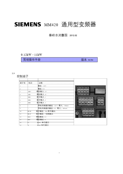
MM420 通用型变频器秦岭水泥许普国2012.020.12kW - 11kW简明操作手册版本04/04 2.3控制端子端子号标识功能1 - 输出+10 V2 - 输出0 V3 ADC+ 模拟输入(+)4 ADC- 模拟输入(-)5 DIN1 数字输入16 DIN2 数字输入27 DIN3 数字输入38 - 带电位隔离的输出+24 V /最大。
100mA9 - 带电位隔离的输出0 V /最大。
100 mA10 RL1-B 数字输出/ NO (常开)触头11 RL1-C 数字输出/ 切换触头12 DAC+ 模拟输出(+)13 DAC- 模拟输出(-)14 P+ RS485 串行接口15 N- RS485 串行接口1电气安装2.4 变频器的方框图PEI IN ,3-4,R=5001/3 AC 200 - 240 V3 AC 380 - 480 V SI+10V10 V2ADC+≥4.7 kΩ3A/DADC-4P0757=2V,P0761=2,IN 4-20mA外接24 V电源DIN15 5DIN1BOP链路RS232150.00BOP/AOPPE L/L1, N/L2或L/L1, N/L2, L3或L1, L2, L3DIN2 DIN26 6 ~DIN3 DIN37 7 = +_ 24 V PNP或8+24V输出最大100 mA(带隔离的)DC+NPN9 9 O0 V最大100 mA((带隔离的)CPU DC−30 V DC / 5 A(电阻负载)250 V AC / 2 A(感性负载) 继电器RL1-B 10RL1-C 110 - 20 mA 最大500 ΩDAC+12DAC-13D/A=3 ~P0778=4,P0781=4,OUT 4-20mAP+14N- 15 RS485 COM链路60 Hz50 HzN未使用1 2DIP开关CB选件自动PE U,V,WMP0003=3,P0004=8,OPEN "ADC" AND"DAC"图2-3 MM420 变频器的方框图MICROMASTER 420 简明操作手册23 工厂的缺省设置MICROMASTER 420 变频器在出厂时具有这样参数设置:即不需要再进行任何参数化就可以投入运行。
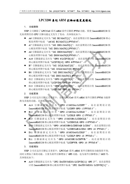
LPC3200系列ARM引脚功能变更情况1. 功能删除NXP公司删除了LPC32x0系列ARM某些引脚的PWM功能,致使SmartARM3250原先原理图里的CPU引脚功能定义发生了变动,具体情况如下:z A6引脚最新定义应为“MS_BS/MAT2[1]”,而在前期设计的SmartARM3250核心板原理图中标成“A6 MS_BS/MAT2[1]/PWM3.6”;z A7引脚最新定义应为“MS_DIO1/MAT0[1]”,而在前期设计的SmartARM3250核心板原理图中标成“MS_DIO1/MAT0[1]/PWM3.2”;z A8引脚最新定义应为“MS_DIO0/MAT0[0]”,而在前期设计的SmartARM3250核心板原理图中标成“MS_DIO0/MAT0[0]/PWM3.1”;z A16引脚最新定义应为“GPO_6/LCDVD[18]”,而在前期设计的SmartARM3250核心板原理图中标成“LCDVD[18] / GPO_6/PWM4.3”;z B7引脚最新定义应为“MS_SCLK/MAT2[0]”,而在前期设计的SmartARM3250核心板原理图中标成“MS_SCLK/MAT2[0] /PWM3.5”;z B8引脚最新定义应为“MS_DIO2/MAT0[2]”,而在前期设计的SmartARM3250核心板原理图中标成“MS_DIO2/MAT0[2] /PWM3.3”;z C12引脚最新定义应为“GPO_9/LCDVD[9]”,而在前期设计的SmartARM3250核心板原理图中标成“LCDVD9 / GPO_09 / PWM4.1”;z C13引脚最新定义应为“GPO_8/LCDVD[8]”,而在前期设计的SmartARM3250核心板原理图中标成“LCDVD8 / GPO_08 / PWM4.2”。
2. 功能更换NXP公司在这次引脚定义变更中,还将LPC32x0系列ARM某些引脚的PWM功能替换为其他的功能,具体情况如下:z A14引脚最新定义应为“GPO_15/MCOA1/LCDFP”,而在前期设计的SmartARM3250核心板原理图中标成“LCDFP/ GPO_15/PWM3.3”;z B12引脚最新定义应为“GPO_12/MCOA2/LCDLE”,而在前期设计的SmartARM3250核心板原理图中标成“LCDLE/ GPO_12/ PWM3.5”;z B13引脚最新定义为“GPO_13/MCOB1/LCDDCLK”,而在前期设计的SmartARM3250核心板原理图中标成“LCDDCLK /GPO_13/PWM3.4”;z D10引脚最新定义应为“GPO_16/MCOB0/LCDENAB/ LCDM”,而在前期设计的SmartARM3250核心板原理图中标成“LCDENAB/LCDM / GPO_16 / PWM3.2”;z D11引脚最新定义应为“GPO_18/MCOA0/LCDLP”,而在前期设计的SmartARM3250核心板原理图中标成“LCDLP /GPO_18 / PWM3.1”;z E11引脚最新定义应为“GPO_10/MCOB2/LCDPWR”,而在前期设计的SmartARM3250核心板原理图中标成“LCDPWR / GPO_10 / PWM3.6”。

RS32通讯板使用说明书版权所有,保留一切权利。
在没有得到本公司许可时,任何单位和个人不得擅自摘抄、复制本书(软件等)的一部分或全部,不得以任何形式(包括资料和出版物)进行传播。
版权所有,侵权必究。
内容如有改动,恕不另行通知。
All rights reserved.The information in this document is subject to change withoutnotice. No part of this document, including electronic, mechanical,micro-coping, photocopying, recording or otherwise, may in anyform or by any means be reproduced, stored in a retrieval system ortransmitted without prior written permission from our company.目录目录1产品介绍-------------------------------------------------------------------------------------------------------------------------- 11.1产品简介----------------------------------------------------------------------------------------------------------------- 11.2产品结构和接口定义------------------------------------------------------------------------------------------------- 1 2产品功能-------------------------------------------------------------------------------------------------------------------------- 5 3适用范围-------------------------------------------------------------------------------------------------------------------------- 5 4主要规格及技术参数 ---------------------------------------------------------------------------------------------------------- 5 5工作条件-------------------------------------------------------------------------------------------------------------------------- 5 6安装调试说明-------------------------------------------------------------------------------------------------------------------- 66.1安装说明----------------------------------------------------------------------------------------------------------------- 66.2调试说明----------------------------------------------------------------------------------------------------------------- 6 7使用维护说明-------------------------------------------------------------------------------------------------------------------- 77.1正常使用说明 ---------------------------------------------------------------------------------------------------------- 77.2一般维护说明 ---------------------------------------------------------------------------------------------------------107.3常见故障及排除方法------------------------------------------------------------------------------------------------101产品介绍1.1产品简介RS32板是能从接收RSL总线上的时钟信号和数据信号,实现楼层数据输出;能提取32个RSL输出信号,用于外部指示;能提取外部32个输入信号,并生成RSL信号用于系统输入;能通过服务器设置这32组输入输出占用RSL总线上的地址。
u Can be used with a wide range of conventionaldetectorsu Monitoring of primary lines for alarms, short circuitsand wire breaksu Conventional detectors can be connected in twostubs or one loopu Individual detector parameters can be programmedfor each stubu Maintains LSN loop functions in the event of wireinterruption or short-circuit thanks to two integratedisolatorsThe FLM‑420/4‑CON Conventional Interface Modulesallow conventional detectors to be connected to LSN fire panels via a 4‑wire supply network (Local SecurityNetwork LSN with external power supply). The interface modules in the 420 series have been specially developed for connecting to the Local SecurityNetwork LSN improved version and offer the enhanced functionality. In classic mode, selected via the integrated rotary switches, the interface modules can be connected to all classic LSN fire panels.System overviewDescription Connection LSN b1+ | a- | b2+LSN (in/out)AUX 2+ | 1/2- | 1+Output power supply 4‑wire detectors OUT1 + | -Stub 1 or loop outOUT2/IN1 - | +Stub 2 or loop inPWR INLSN AUX or EXT.PWR + | -Input power supply (from LSN or external source)Features conventional linesIndividual detector parameters can be programmed for each stub. Within one stub or loop the detector parameters have to be consistent.Only one EOL resistance can be selected for each interface module.The detector voltage AUX (supply to 4‑wire detectors) can be switched on or off for each line individually. For configurations with only one stub or one loop the two outputs AUX with 200 mA maximum current intensity can be switched in parallel.If a line has only 2‑wire detectors connected, the AUX output of this line might be switched in parallel with the AUX output of the second line (with 4‑wire detectors). In this case, both AUX outputs are reset in parallel at once.If both lines have only 2‑wire detectors connected, both AUX outputs are set off.The detector lines are short-circuit proof. In the event of a short circuit on the line, a fault message is sent to the control panel.In the event of a line interruption in the loop, the loop is split into two stubs to retain all detectors.The system detects removal of detectors and indicates a fault message on the fire panel.The fire panel detects a ground connection for each individual line.LSN featuresIntegrated isolators ensure that function is maintained in the event of a short circuit or line interruption in the LSN loop. A fault indication is sent to the fire panel. Interface module functionsA red flashing LED on the device indicates the alarm of one or both primary lines.Current values and other parameters can also be displayed.Address switchesThe rotary switches integrated in the interface module can be used to select automatic or manual addressing with or without auto detection.The following settings are possible:Features of LSN improved versionThe interface modules in the 420 series offer all the features of the improved LSN technology:•Flexible network structures including T‑tappingwithout additional elements•Up to 254 LSN-improved elements per fire panel loop or stub line•Rotary switches allow operator to select automaticand manual addressing, either with or without autodetection•Unshielded cable can be used•Downwards compatible with existing LSN systemsand control panelsInterface variantsDifferent versions of the interface module are available:•FLM‑420/4‑CON‑S for surface-mount installation with housing•FLM‑420/4‑CON‑D for installation via an adapter on a DIN rail or in a FLM‑IFB126‑S surface-mountedhousingCertifications and approvalsComplies with•EN54-17:2005•EN54-18:2005Installation/configuration notes•Can be connected to the fire panels FPA‑5000 andFPA‑1200 and the classic LSN fire panels BZ 500 LSN, UEZ 2000 LSN and UGM 2020.•For compatible devices, please refer to theCompatibility List (document number F.01U.079.455) available for download at /emea/fire.•Programming is done with the programming software of the fire panel.•Within one stub (class B) or loop (class A) thedetector parameters have to be consistent (e.g.standby current, alarm resistance).•Loop wiring of the conventional zone (class A) doesnot require an EOL resistor as it is already integrated in the interface module.•The power supply is provided via the two wires onthe auxiliary LSN power supply or by an externalpower supply unit. External power supply units must be free-of-ground.•The surface-mounted housing has two cable ducts on opposite sides:– 2 x 2 pre-punched cable ducts for diameter up to21 mm/to 34 mm (for conduits)– 2 x 4 rubber bushes for inserting cables with diameters of up to 8 mm•In addition, there are cable ducts on the base of thesurface-mounted housing:– 1 x pre-punched cable duct for diameter up to21 mm (for conduits)– 2 x 4 rubber bushes for inserting cables with diameters of up to 8 mm•For operating the fire alarm system according toEN 54-13:–it is necessary to terminate every conventional zone with EOL modules–conventional 4-wire detectors must be supplied by an external power supply. The FLM‑420/4‑CONConventional Interface Module must be suppliedby the auxiliary LSN power supply•Observe the maximum line resistance of 25 Ω forconventional lines with manual call points orautomatic fire detectors.Type Qty.ComponentFLM-420/4-CON-S1Conventional Interface Module for 4-wireLSN, with surface-mounted housing,cable with EOL resistor (3k92)FLM-420/4-CON-D 1Conventional Interface Module for 4-wire LSN, with adapter for installation on aDIN rail in accordance with EN 60715,light pipe, cable with EOL resistor (3k92) 2 2.2 kOhm resistorsElectricalof the internal module hardware and the conventional line(s) supervision. The power consumption of the connected devices is excluded:* number of zones used x EOL resistor applied on the zone(s)MechanicsEnvironmental conditionsOrdering informationFLM‑420/4‑CON‑S Conventional Interface Module 4‑wire LSNwith 2 primary lines for 2- or 4-wire conventional detectors, with surface-mounted housingOrder number FLM-420/4-CON-S FLM‑420/4‑CON‑D Conventional Interface Module 4‑wire LSNwith 2 primary lines for 2- or 4-wire conventional detectors, type DIN railOrder number FLM-420/4-CON-DAccessoriesFLM‑IFB126‑S Surface-mounted Housingas retainer for the interface modules series 420 type DIN rail (-D) or spare housing for type surface-mount (-S)Order number FLM-IFB126-SRepresented by:Europe, Middle East, Africa:Germany:North America:Asia-Pacific:Bosch Security Systems B.V.P.O. Box 800025600 JB Eindhoven, The Netherlands Phone: + 31 40 2577 284****************************** Bosch Sicherheitssysteme GmbHRobert-Bosch-Ring 585630 GrasbrunnGermanyBosch Security Systems, Inc.130 Perinton ParkwayFairport, New York, 14450, USAPhone: +1 800 289 0096Fax: +1 585 223 9180*******************.comRobert Bosch (SEA) Pte Ltd, Security Systems11 Bishan Street 21Singapore 573943Phone: +65 6571 2808Fax: +65 6571 2699*****************************© Bosch Security Systems 2016 | Data subject to change without notice 1294077835 | en, V8, 19. Sep 2016。
同步图形存储器IS42G32256的原理与应用摘要: IS42G32256是高速度16M bit CMOS同步图形存储器(SGRAM),适用于高性能计算机的显示卡、图形工作站、电视机顶盒、游戏卡、二维/三维图形处理等场合。
对其功能、特点、工作原理及其应用进行了介绍。
关键词: SGRAM CMOS IS42G32256 图形处理半导体存储器是计算机系统的重要组成部分,随着计算机技术的迅速发展,CPU的速度越来越高,以往采用的普通动态存储器(DRAM)速度低,带宽窄,已无法适应高速CPU。
为了适应各种实际应用的需要,出现了采用新技术的DRAM。
其中同步DRAM(SDRAM)的出现,大大地提高了存储器的速度,改善了其性能。
在高性能计算机系统中,常用SDRAM作为主存储器和显示存储器。
如果将图形特点加入到SDRAM中,即得到同步图形存储器,简称SGRAM。
IS42G32256是高速16M bit CMOS同步图形存储器,性能优良,速度快,适合于图形工作站、显示卡、电视机顶盒、游戏卡、二维/三维图形处理等高性能、高带宽的应用场合。
它具有以下特点:①256K×32位×2存储体结构;②所有输入采样和输出都在同一个系统时钟的上升沿同步动作;③双重内部存储体控制;④单3.3V±3V电源;⑤可编程方式寄存器指定突发范围为1、2、4、8字节或整页,/CAS等待周期为2和3周期,突发类型为顺序和交替;⑥突发读写操作;⑦刷新能力为自动和自举刷新;⑧每32ms刷新2048周期;⑨输入输出电平与TTL电平兼容;⑩100引脚PQFP封装(14mm×20mm)。
它具有以下图形特点:①SMRS周期:装载屏蔽寄存器,装载颜色寄存器;②写每位;③块写(8列)1 工作原理IS42G32256 SGRAM的基本组成是两个结构为1024×256×32位的存储体,功能框图>"/UpLoadFiles/Editor/2005-11-2/2005112162116288.gif">见图1。
HS520A模块使用说明Ver 1.00深圳华视电子读写设备有限公司1.适用范围HS520A读写模块,适用于IS014443A协议下的各种应用。
目前该版本只支持S50,S70等各种Mifare1卡片的读写。
2.HS520A模块简介单片机UART的典型接口。
2.3技术参数块。
3.2控制字符定义下表列出了HS520A与主机串行通信过程中用到的控制字符定义。
表4.HS520A串行通信控制字符表描述定义值开始符(主机-HS520A)STX0x0A 终止符(主机-HS520A)ETX0x0B 开始符(HS520A-主机)STX0x0C 终止符(HS520A-主机)ETX0x0D数据帧接收规则:l一帧的结束一定是ETX,但接收到0x0B则不一定是帧结束;l帧长必须不小于6字节,最大不能超过64字节。
l BCC计算必须正确。
3.3.2主机发送命令至模块通信必须先由主机发送命令和数据给HS520A,HS520A执行命令完毕后,再将执行命令后的状态和响应数据发回给主机。
用户在给HS520A模块发送命令时,连续的发送STX (0x0A)+…+0x0B(结束符)。
通过判断HS520A返回数据的正确性来判断HS520A是否正确执行了本条命令。
0x85:发送帧帧尾错误0x8C:发送帧CMD 错误2.2.射频芯片启动配置(发送帧:主机射频芯片启动配置(发送帧:主机射频芯片启动配置(发送帧:主机-HS520A -HS520A -HS520A)复位通信芯片并打开天线)复位通信芯片并打开天线。
STX SEQNR CMD Length DATA BCC ETX 0x0A自定义0xA2/计算结果值0x0B应答(接收帧:HS520A-主机)STX SEQNR Status Length DATA BCC ETX0x0C同发送帧0/计算结果值0x0D Status:0x00:操作成功0x81:发送帧帧头错误0x84:发送帧BCC错误0x85:发送帧帧尾错误应答(接收帧:HS520A-主机)STX SEQNR Status Length DATA BCC ETX0x0C同发送帧TagType,UID,SAK计算结果值0x0D Status:0x00:操作成功0x82:寻卡失败0x83:防冲突失败0x81:发送帧帧头错误0x84:发送帧BCC错误0x85:发送帧帧尾错误0x8C:发送帧CMD错误Length:4字节+序列号的长度Mifare1S50、S70、Light卡:8字节Mifare0UltraLight和Mifare3Desfire卡:11字节DATA[0..1]:*TagType:请求应答,2个字节的卡片类型,见表13,14。