Descriptions,Aims and Scopes
- 格式:pdf
- 大小:331.63 KB
- 文档页数:1

frontiers的scope statement模板Frontiers 是一家学术出版社,提供开放获取的科学研究平台,拥有一系列的学术期刊。
每个期刊都有其独特的范围(scope),而"scope statement"(范围声明)则是用于明确期刊研究领域和内容的文档。
虽然每个期刊的"scope statement" 可能会有所不同,但通常包含以下元素:1.期刊标题:明确期刊的名称。
2.目标和愿景:描述期刊的主要目标和愿景,包括促进什么样的学科领域或研究方向。
3.研究领域:定义期刊关注的具体研究领域,可以是学科、学科交叉领域、主题等。
4.论文类型:指明期刊接受的论文类型,例如原始研究、综述、方法论、评论等。
5.审稿政策:说明期刊的审稿流程、审稿人要求、对稿件的评审标准等。
6.开放获取政策:如果期刊是开放获取的,提供关于开放获取政策和费用的信息。
以下是一个可能的Frontiers 期刊的"scope statement" 模板示例:# [期刊名称] 范围声明## 目标和愿景[期刊名称] 旨在成为[领域]领域中的前沿科研平台,促进学科的发展和创新。
我们致力于提供高质量的开放获取出版服务,为学术界和科研人员提供一个分享研究成果的国际性平台。
## 研究领域[期刊名称] 关注的研究领域包括但不限于:- [领域1]- [领域2]- [领域3]## 论文类型[期刊名称] 欢迎以下类型的论文投稿:- 原始研究- 综述- 方法论- 评论## 审稿政策[期刊名称] 采用严格的同行评审制度,确保所有接受发表的论文都经过专业评审。
我们鼓励广泛的国际同行专家参与审稿过程。
## 开放获取政策[期刊名称] 是一家开放获取出版商,所有发表在本期刊的论文都可免费访问。
我们鼓励作者和读者一同分享知识,促进科研成果的传播。
如有任何问题或需要进一步信息,请联系我们:[联系方式]。

英语段落简称
本文将介绍一些常用的英语段落简称,以便读者更好地理解英语文章和文本。
这些简称通常在学术论文、报告、新闻稿件、社交媒体和其他文本中使用。
以下是一些常见的英语段落简称:
1. Introduction:简称为'Intro'
2. Abstract:简称为'Abs'
3. Literature Review:简称为'Lit Review'
4. Methodology:简称为'Method'
5. Results:简称为'Res'
6. Discussion:简称为'Disc'
7. Conclusion:简称为'Concl'
8. Recommendations:简称为'Recs'
9. Acknowledgments:简称为'Acks'
10. References:简称为'Refs'
11. Appendix:简称为'Appx'
需要注意的是,这些简称可能因不同领域和文体而有所差异,因此在使用时请根据具体情况选择恰当的缩写。
- 1 -。
SCI论文准备写作投稿技巧常用英文词汇1. Introduction:- Present study: 本研究- In this paper: 在本文中- The objective of this study: 本研究的目标- To investigate: 研究- Background: 背景- Previous research: 先前的研究- Research gap: 研究空白- Methodology: 方法论- Data analysis: 数据分析- Findings: 研究结果- Conclusion: 结论2. Literature Review:- Literature review: 文献综述- Scholarly articles: 学术文章- Theoretical framework: 理论框架- Empirical evidence: 实证证据- Research methods: 研究方法- Key findings: 主要发现- Implications: 启示3. Methods:- Study design: 研究设计- Data collection: 数据收集- Sample size: 样本量- Research instruments: 研究工具- Data analysis techniques: 数据分析技术- Statistical analysis: 统计分析- Control variables: 控制变量4. Results:- Descriptive statistics: 描述性统计- Correlation analysis: 相关分析- Regression analysis: 回归分析- Significant findings: 显著性发现- Patterns and trends: 模式和趋势5. Discussion:- Implications: 启示- Limitations: 限制- Future research directions: 未来研究方向- Theoretical contributions: 理论贡献- Practical implications: 实践意义6. Conclusion:- Summary: 总结- Contributions: 贡献- Future research: 未来研究- Practical implications: 实践意义。

HOW TO WRITE A RESEARCH PAPERThis introductory guide is aimed at researchers at the beginning of their careers intending to write papers for publication in APEX and JJAP. It will provide a few tips for writing papers on your research results.1. Where to submit your paperIt is beneficial to decide on a target journal (APEX or JJAP) and type of paper (Letters for APEX; Regular Paper (RP), Rapid Communication (RC), and Brief Note (BN) for JJAP) at very beginning of your writing. This is useful because different journals and paper types have different scientific scopes and aims and different manuscript requirements in terms of length, style, and format. By directly targeting your journal and paper type, you can ensure the right approach and speed up the manuscript preparation.2. How to construct your paperA full length paper published in JJAP comprises the following components, and the main text is sectioned accordingly. Although Letters in APEX and Rapid Communications and Brief Notes in JJAP are not sectioned, the essential flow of presentation is usually the same in all types of paper.TitleThe title should be brief, but must be appropriate for the content, informative and clear. If the work is of interest in a limited area of research, indicate it in the title. Many people will read the title, but papers with poor or improper titles may never be actually read by the intended audience.AuthorsAll your coworkers who have made significant scientific contributions to the research and have agreed to submitting the paper should be included as coauthors. Every coauthor should be aware of the content of the paper and share appropriate responsibility for the work. The affiliation at which the research work was conducted must be provided for each of the authors.AbstractThe abstract concisely states the objectives and scope of research, and summarizes the results and principal conclusion gained in your research work. A well-written abstract, together with the title, enables potential readers to determine whether your paper isinteresting and worth reading in full. Abstracts must be concise, generally presented as one paragraph, and the length should not exceed 150 words for JJAP regular papers, 100 words for APEX letters and JJAP short papers.IntroductionThe introduction is a critical part of your paper because it introduces the reasons behind your paper’s existence. It must state the objectives and scope of your work, present what problem or question you address, and describe why this is an interesting or important challenge. It is important to introduce appropriate and sufficient references to prior works so that readers can understand the context and background of the research and the specific reason for your research work. Having explored those, the objectives and scope of your work must be clearly stated. The introduction may explain the approach that is characteristic to your work, and mention the essence of the conclusion of the paper.MethodsThe Methods section provides sufficient detail of theoretical and experimental methods and materials used in your research work so that any reader would be able to repeat your research work and reproduce the results. Be precise, complete and concise: include only relevant information. For example, provide a reference for a particular technique instead of describing all the details.ResultsThe Results section presents the facts, findings of the study, by effectively using figures and tables. This section must present the results clearly and logically to highlight potential implications. Combine the use of text, tables, and figures to digest and condense the data, and highlight important trends and extract relationships among different data items. Figures must be well designed, clear, and easy to read. Figure captions should be succinct yet provide sufficient information to understand the figures without reference to the text.DiscussionIn the Discussion section, present your interpretation and conclusions gained from your findings. You can discuss how your findings compare with other experimental observations or theoretical expectations. Refer to your characteristic results described in the Results section to support your discussion, since your interpretation and conclusion must be based on evidence. By properly structuring this discussion, you can show how your results can solve the current problems and how they relate to the research objectives that you have described in the Introduction section. This is your chance to clearly demonstrate the novelty and importance of your research work.ConclusionsThe Conclusion section summarizes the important results and impact of the research work. Future work plans may be included if they are beneficial to readers.AcknowledgmentsThe Acknowledgments section is to recognize financial support from funding bodies and scientific and technical contributions that you have received during your research work.ReferencesThe References section lists prior works referred to in the other sections. It is vitally important from an ethical viewpoint, to fully acknowledge all previously published works that are relevant to your research. Whenever you use previous knowledge, you must acknowledge the source. Readers benefit from complete references as it enables them to position your work in the context of current research. Ensure that the references given are sufficient as well as current, and accessible by the readers.3. Writing and editingThe following tips may be useful in writing the paper.- You need not start writing the text from the Introduction. Many authors actually choose to begin with the results section since all the materials that must be described are available.This may provide good motivation for carrying out the procedure most effectively.- Your paper must be interesting and relevant to your readers. Consider what your readers want to know rather than what you want to write. Describe your new ideas precisely in an early part of your paper so that your results are readily understood. Otherwise, do not use lengthy descriptions of the details. For example, writing too many equations and showing resembling figures or too much detailed tables should be avoided. Clarity and conciseness are extremely important.- During and after writing your draft, you must edit your writing by reconsidering your starting plan or original outline. You may decide to rewrite portions of your paper to improve logical sequence, clarity, and conciseness. This process may have to be repeated over and over.- When editing is completed, you can send the paper to your co-authors for improvement.When all the co-authors agree on your draft, it is ready to be submitted to the journal. It is worth performing one final check of grammatical and typographical errors.- English correction of the manuscript by a native speaker is highly recommended before your submission if you are not a native speaker. Unclear description prohibits constructive feedback in the review process.4. Peer review processWhat is peer reviewA paper submitted to the Journal is reviewedanonymously by independentexperts in the field (peers) todetermine whether the paper issuitable for publication. In thereview process, the originality,technical quality, and impact ofthe research work are criticallyevaluated, and the editors ofthe journal then make apublication decision on thebasis of reviewers’ reports. The peer review process helpseditors to decide what topublish, and it ensures the quality and credibility of thepapers. The reviewer willidentify any fault in your paper and provide constructivefeedback to you so that you canimprove your work beforepublication. Other experiencedresearchers in the field provide this service to you, and as a good member of the scientific community, you are expected to reciprocate by reviewing papers when you become experienced in your research field.A simplified flowchart of peer review is illustrated in the figure.Roles of the editor and reviewerWhen your paper is submitted to the journal office, a general check of the paper’s suitability, such as the manuscript format and length, and the matching of research scope is conducted at the journal office. If it is judged to be suitable, the editor will ask a reviewer to evaluate your paper.The reviewer is asked to evaluate your paper from a variety of aspects such as the novelty and originality of research, the importance and impact of results, the logic, style, length, and clarity of presentation, and the completeness of references. The reviewer provides a report including various comments and recommendations for improvement.On the basis of the reviewer’s report, the editor will make one of the following decisions on your.Review process Received Rejected Rejected Accepted forpublication Editor ReviewerAuthor’srevision- Accept for publication without revision-Ask for minor revision for likely acceptance - Request major revision for another review process- Reject outrightNotification of review resultThe corresponding author will be notified of the results of the review through an e-mail that will prompt the author to log onto the JJAP&APEX Online Submission System to view the detailed comments and further suggestions. If a minor or major revision is required or suggested, you are requested to complete it by the specified date. If you are notified of the unacceptability of your paper, you are welcome to submit a new manuscript to JJAP or APEX after making major improvements or rewriting the paper in line with the reviewer's and editor's comments. Should you disagree with the decision of rejection, you can make one appeal against rejection in writing.5. Manuscript revision and response to reviewer reports When a revision is required, you should consider each reviewer’s report very carefully and respond to each comment by adding new data or making editorial changes. If you disagree with the reviewer, you are not obliged to do what is asked, but you must provide a convincing explanation in your response. To maintain the journal’s policy of timely publication, you are encouraged to finish your revision as promptly as possible. In particular, for APEX papers, you are requested to complete the revision within two weeks. If the revision cannot be finished within the journal’s time limit, the manuscript will be regarded as having been withdrawn. On submitting the revised manuscript, you are advised to attach a detailed point-by-point reply to all the reviewer’s recommendations and comments together with a list of the manuscript changes you have made. The simplest procedure is to copy each of the reviewer’s comments and present your response immediately after. It will be helpful to the reviewer if the locations of manuscript changes are indicated, for example, in the attached second copy of the manuscript with the changes highlighted. These documents will normally be forwarded to the reviewer. It is recommended that you start a reply by thanking the reviewer for their insightful and helpful comments. Then you should always be respectful in explaining the details of and reasons behind the revisions you have or have not made. Your revised manuscript will be checked by the editor. If major amendments were requested, your paper will be sent to the original reviewer for another evaluation. If the reviewer is satisfied with your revision, the paper will be accepted for publication by the editor. If yourrevision is unsatisfactory, the reviewer and editor may request further improvement. Letters submitted to APEX are allowed only a single revision because of the strict policy of prompt publication, and Letters judged to require major revisions will be rejected.6. Ethical issues in paper writingCo-authorshipAll individuals who made significant scientific contributions to the research work should be given the opportunity to be included as coauthors. Other persons who contributed to the study should be acknowledged, but need not be identified as coauthors. Every coauthor should be aware of the content of an article to be submitted, agree to its submission, and share appropriate responsibility for the work. Any individual unable to take appropriate responsibility for the article should not be included as a coauthor.Duplicate or multiple submissionDuplicate or multiple submission is the most common ethics violation encountered. It is unethical for authors to publish articles describing essentially the same research result in more than one journal. It is also unacceptable for authors to submit the same manuscript concurrently to more than one journal.Fabrication or falsification of dataThe fabrication or falsification of data or reporting of intentionally selective data to mislead or deceive the readers is a serious departure from professional conduct. Authors should strive to prevent mispresentation of their data and the inclusion of the data or research results of other works without permission from the original authors or publishers.Plagiarism and self-plagiarismAuthors should not use, without attribution, text, concepts, data, figures, or tables from another work published either by others or by themselves. Plagiarism of others’ works and self-plagiarism are serious breaches of ethics and are not tolerated. If a direct quotation is appropriate, the original source should be properly cited. Figures, tables, and other images reproduced from another source normally require the publisher’s permission.Conflict of interestAny potential conflicts of interest (e.g., employment, stock ownership, patent licenses, etc.) should be reported to the editorial office. These include personal, academic, political, financial and commercial gains.Released May 2013© 2013 The Japan Society of Applied Physics。
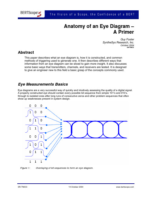
Anatomy of an Eye Diagram –A PrimerGuy FosterSyntheSys Research, Inc.October 2004SR-TN033 AbstractThis paper describes what an eye diagram is, how it is constructed, and commonmethods of triggering used to generate one. It then describes different ways thatinformation from an eye diagram can be sliced to gain more insight. It also discussessome basic ways that transmitters, channels, and receivers are tested. It is designedto give an engineer new to this field a basic grasp of the concepts commonly used.Eye Measurements BasicsEye diagrams are a very successful way of quickly and intuitively assessing the quality of a digital signal.A properly constructed eye should contain every possible bit sequence from simple 101’s and 010’s, through to isolated ones after long runs of consecutive zeros and other problem sequences that oftenshow up weaknesses present in system design.Figure 1: Overlaying of bit sequences to form an eye diagram.What does it show?Eye diagrams show parametric information about the signal – effects deriving from physics such as system bandwidth health, etc. It will not show protocol or logical problems – if a logic 1 is healthy on the eye, this does not reveal the fact that the system meant to send a zero. However, if the physics of the system mean that a logic one becomes so distorted while passing through the system that the receiver at the far end mistakes it for a zero, this should be shown in a good eye diagram.Common ways of characterizing an eye are to measure the rise times, fall times, jitter at the middle of the crossing point of the eye, the overshoot present and many other numerical descriptions of eye behavior in order to compare devices being measured. Instruments usually offer automated measurements that simplify and speed up the taking of such measurements.The Effects of Triggering on Eye DiagramsMany eye diagrams are constructed on test equipment that uses test patterns that repeat, such as PRBS patterns generated by a BERT (Bit Error Ratio Tester). Such equipment can commonly generate a variety of trigger signals:1) A clock trigger at the same rate as, and synchronous with the data signal2) A divided clock trigger at some divide ratio of the data rate often related to a power of 2such as ÷4, ÷16, etc.3) A pattern trigger – a signal that provides a trigger once per pattern repetition.4) The data itself can be used as a trigger.5) The last option is to derive the trigger signal by using clock recovery on the data signal. Each method provides different results when used to construct a waveform.Clock Trigger provides a classical eye diagram containing all possible bit transitions in one display.Figure 2: An eye diagram formed with a full rate clock triggerDivided Clock Trigger also produces an eye diagram, and this can be useful when the instrument being used to construct the eye has a trigger input bandwidth narrower than the data rate of the signal being viewed. This method can produce a good eye unless the pattern length divided by the divide ratio yields an integer – for example a 128-bit pattern viewed with a ÷4 clock. In this case, the trigger signal will coincide with the same bits in the pattern each time while consistently missing other parts of the pattern – leading to an incomplete eye.Figure 3: An eye diagram formed with a divided clock triggerPattern Trigger: Used to display individual bits in the pattern. To view the whole pattern, the user must scroll through by altering either the time base of the scope or the pattern trigger position. Scrolling using the extent of a scope time base can lead to increased apparent jitter on the displayed signal due to weaknesses in time base circuitry; incrementing a pattern trigger, either within the BERT or within some more sophisticated scopes is preferable to avoid this problem.Figure 4: A bit sequence captured using a pattern triggerTriggering on Data is the least satisfactory method of constructing an eye and should only be used as a quick look-see. Long runs of identical characters provide no transitions to trigger from, and so a complete eye is almost impossible to achieve.Figure 5 An incomplete eye diagram formed by triggering on dataTriggering from a Recovered Clock: While increasing complexity, this method has some advantages: •In some situations a clock signal is not available and so must be derived•In other cases, particularly long distance fiber optic communications, the relationship between the clock at the transmit end and the data at the receive end may be corrupted by rapidly time-varying effects in the transmission path.•Lastly in cases where the receiver uses clock recovery and the eye as seen by the receiver needs to be examined – this can be required by some standards, particularly for jitter testing. Circuits used for recovering clock typically have a loop bandwidth, or filtering function, that removes from the clock signal some of the jitter that was present on the data signal. Depending upon the measurement being made, this can be helpful or hurtful, but needs to be understood.Narrow loop bandwidth clock recovery tends to give a rock solid clock trigger signal as the reference, and any jitter, or movement of edges with time, in the data eye diagram that is present will be displayed. This is a useful absolute measure but might not properly represent the jitter seen by a real system if the receiver uses clock recovery to track some of the jitter out.Figure 6: An eye diagram triggered from a clock recovered from the data signal using a narrow loop bandwidth clock recovery scheme.Wide bandwidth clock recovery tends to let more of the jitter that was present on the data signal through on to the clock. This can mean that as the data jitters by moving edges in one direction, then the other; the recovered clock tracks it, and the resulting eye appears to have very little jitter present on it. This tracking function is the way many system receivers work to reduce the jitter passed on through the system.Figure 7: An eye diagram triggered from a clock recovered from the data signal using a wide loop bandwidth clock recovery scheme.Conditions can also conspire to create the opposite effect – where the delay between data signal and trigger signal is such that when the data edges are moving to their furthest extent in one direction, the recovered clock signal being triggered from it is moving to its furthest extent in the other, and the resulting eye shows as much as twice the jitter that was present on the data signal.Figure 8: An eye diagram triggered such that the delay between jittered clock and jittered data destructively interferes.While the last situation is seldom desirable, the first two situations, where all jitter is shown and where most jitter is tracked out, have their uses depending upon what information is being sought with the measurement. Luckily, most standards specify what triggering scheme is required to make measurements.Eye Diagrams and BERWhile eye diagrams provide an accessible and intuitive view of parametric performance, systems ultimately are judged on their ability to pass bits faithfully, and without error. The BER, Bit Error Ratio, or Bit Error Rate as it is sometimes called, is a ratio of the number of bits received incorrectly (errors) divided by the total number of bits received. This provides an overall score for how well a system is performing, but provides little help on why performance might be below expectations. It should be noted that BER tests logical problems as well as parametric ones – whether the correct bit was sent in the first place.So why don’t eye diagrams and BER easily link together? A perfect eye diagram would show all parametric aspects of all possible bit sequences, irrespective of how infrequently some effects show up. In other words, it would have a high information depth. Typically, eye diagrams are composed ofvoltage/time samples of the original data, acquired at some sample rate that is orders of magnitude below the data rate. For sampling oscilloscopes, this can be 105 samples per second at a 10 Gb/s (1010bits/second) rate. This means that most eye diagrams are composed of shallow amounts of data.This becomes a problem when issues arise that are infrequently occurring. These can be pattern related, noise related or deriving from other effects such as crosstalk and other forms of interference. These may not be visible in an oscilloscope eye diagram, but prevent link performance to desired levels. Forexample, links are often required to work to better than one error in a million, million bits (1x10-12 BER), while eye diagrams struggle to show events with probabilities below an occurrence of 1x10⁻⁵.This leaves an information gap that can be solved in a number of ways. The first is to construct the eye diagram from voltage/time measurements taken with an architecture that has a higher sampling efficiency. Systems such as the BERTScope are capable of perhaps three orders of magnitude more depth than sampling scopes.The second solution is to use the fact that a BERT samples data directly at the line rate, and so is better equipped to see rare events that will limit system performance.Slicing the EyeTypical receivers are designed to make a decision at an instant in time as to whether the signal is above or below a particular threshold voltage.Figure 9: A receiver decision point in the center of the eye.From this it decides whether the incoming signal is a data 1 or data 0. Sensible system designers place this decision point as far as possible from rising edges, falling edges, high level and low level – in other words in an unobstructed part of the eye, usually the center. Most BERT instruments have the ability to move this decision point away from the optimum position in time and/or voltage. By moving the decision point, it is possible to probe other parts of the eye, and by measuring the errors encountered, profile the anatomy of the eye diagram.Probing Jitter is a common test carried out with a BERT, done by probing through the crossing point of the eye. This measurement has been given various names including BERTScan, Bathtub Jitter, and Jitter Peak. It is more fully described in MJSQ i. This measurement taken by a BERT has the advantage that the BERT sees every bit, and so is most likely to capture rare jitter events.Figure 101 (a), (b), (c): Moving the BERT decision point in time to trace out the BER profile of thecrossing point.Probing Signal-to-Noise: A second common eye test that arose out of the fiber optics industry ii is Q-Factor. This is particularly useful in systems whose performance is limited by noise. Here the decision point is used to probe a vertical slice through the eye halfway through the bit period. Measuring the way the BER rolls off towards the middle of the eye gives an indication of how much noise is present and how it will impact the link.Figure 11 (a), (b): Moving the BERT decision point in voltage to trace out the BER profile of the one and zero levels.BER Contour is a superset of the last two measurements, and also the perfect linkage between BER and eye diagrams. Here the decision point is stepped around the inside of the eye and the BER profile mapped out on a series of angled slices around the eye. This provides a much more complete and clearer picture of where system parametric problems may be lurking. The BERTScope has been optimized to make this a fast and revealing measurement.Figure 12 (a), (b): Slicing the eye along multiple axes to form an eye contour.The need for speedThe practicalities of these measurements are that a single point BER measurement of 1x10-12 at 10 Gb/s takes several minutes. Given that many systems are expected to function to better than 1x10-15 BER, where a single point could take months to measure, the ability to take quicker measurements and then extrapolate is valuable. The key is that BER contour measurements can be made quickly that are already down to near the levels where results are required and so the inaccuracies in extrapolating can be greatly minimized.Testing TransmittersEye diagrams are commonly used for testing transmitters. As test equipment input characteristics vary, a standardized method of test, called a reference receiver, has been devised by international standards iiisuch as the ITU for equipment used to test optical transmitters. Similar use of the input filter is also appearing now in some electrical standards.Figure 13: Block diagram of a reference receiver.The aim is that the overall frequency response of the measuring system be well controlled, following a 4th order Bessel-Thompson curve within a defined tolerance window, with a systems -3 dB point at 0.75 of the bit rate. In theory, this means that measurements taken with different instruments should be comparable.Figure 14: An eye mask testMask testing is an abbreviated eye diagram test for the quick testing of transmitters in manufacturing. Rather than measuring all parametric aspects of the eye, mask testing defines key areas in the eye that are deemed to be “keep-out” areas – if any of the signal is detected to be in this region, then the device fails. Mask testing is often carried out in a few seconds. It should be noted that mask testing only detects gross problems in transmitters – it simply does not have the data depth in a short time to trap rare events, although instruments such as the BERTScope acquire significantly more data in a few seconds than most instruments.Testing ChannelsChannels can be tested as an independent element, or as a combination of transmitter and channel. Testing of the channel as an independent entity is often carried out by measuring parametric characteristics such as loss, attenuation, reflection, and dispersion. This applies in optical links cases and in electrical links, although in short distance electrical cases such as back planes, s-parameter measurements are often used as an accurate description of all of the parameters mentioned above. One challenge with characterizing a channel as an independent entity is how to translate the measurements taken into what the eye and BER will be like at the end of a link. Modeling programs such as StatEye iv attempt to convert parametric characterization into a predicted BER contour.Another approach is to measure the channel with a representative transmitter. This has the disadvantage of presenting a challenge to de-convolve the contributions from transmitter and channel, but has the advantage of allowing direct measurement of eye characteristics and BER performance. This can beuseful as a way of generating a measured BER contour that can then be compared with the modeled results of a program like StatEye.BER Contours in three dimensions – the Eye BowlA good visualization of the health of the eye, including the effects of rare events, can be obtained by plotting BER contour in three dimensions.Figure 15: (a) Eye Diagram, (b) BER Contour, (c) Eye BowlTesting ReceiversTraditionally receiver testing has been a BER test rather than an eye-related test. The input signal to the receiver is reduced in size and often impaired in other ways so that it represents the limit of the conditions that the device under test will see. If the receiver is able to function error-free then it passes.An interesting twist on receiver testing is in measuring jitter tolerance, or the ability of the receiver to make the correct decision on each incoming bit even when the signal data edges are moving erratically in time. As discussed earlier, clock recovery will often remove much of this jitter. In the SONET/SDH world, jitter tolerance testing was achieved by deterministically moving the data edges in time using an injected sinusoid that was varied in amplitude and frequency according to a template. More recently, the concept of a Stressed Eye has been introduced, where the edges of the data are corrupted by various different means. This has developed beyond just a jitter test, as impairments are also added in the amplitude dimension, as shown elsewhere on this poster. The general idea is that the stressed eye is set to be the worst case operating conditions that the receiver would ever see, and if it is able to operate error-free in the presence of such a signal, the device passes.Figure 16: A stressed Eye.ConclusionThere can be an immense amount of information stored in an eye diagram if it is taken correctly, and to enough data depth. This can tell a designer a lot about the parametric performance of his design, and a manufacturing engineer whether parts will cause problems in the field later.Referencesi MJSQ - Methodologies for Jitter and Signal Quality Specification is a document written as part of the INCITS project T11.2. /index.htmii N.S. Bergano, F.W. Kerfoot, and C.R. Davidson, "Margin Measurements in Optical Amplifier Systems, " in IEEE Photonics Technology Letters, vol. 5, no. 3, pp. 304-306, Mar. 1993.iii TIA/EIA-526-4-A Optical Eye Pattern Measurement Procedure (/standards/) Also measuring optical SDH transmitters: ITU G.957, Similarly for SONET transmitters: Bellcore GR-253-COREiv Stateye modeling of channel responses to predict BER Contour: Copyright © 2004 SyntheSys Research, Inc. SyntheSys is a registered trademark of SyntheSys Research, Inc. All rights reserved.。

学术英语词汇大全学术领域对于学术英语词汇的需求极为重要。
准确且丰富的学术词汇不仅能够提升学术论文的质量,还能够帮助学者更好地理解和沟通学术研究。
本篇文章旨在为读者提供一份学术英语词汇大全,以便在学术写作中增强表达能力和准确性。
一、研究方法与设计(Research Methods and Design)1. 实证研究(Empirical Research)- 使用观察和实验证据作为研究的基础,旨在验证假设或理论。
2. 实验研究(Experimental Research)- 在控制条件下对研究对象进行干预和观察,以验证因果关系。
3. 定量研究(Quantitative Research)- 依赖于数量化数据和统计分析,以验证和解释现象之间的关系。
4. 定性研究(Qualitative Research)- 通过收集和分析非数量化数据,探索现象背后的深层意义和理解。
5. 横断面研究(Cross-sectional Study)- 在特定时间点上收集数据,以了解不同变量之间的关系。
6. 纵向研究(Longitudinal Study)- 对同一群体进行多次观察,以了解变量随时间的变化。
7. 质性研究(Mixed Methods Research)- 结合定量和定性研究方法,以全面理解研究对象。
二、文献综述和理论框架(Literature Review and Theoretical Framework)1. 学术论文(Academic Paper)- 详细描述研究问题、方法、结果和结论的学术文章。
2. 文献综述(Literature Review)- 对已有文献进行全面评估和分析,以支持研究问题和方法的选择。
3. 引用文献(Citation)- 在学术论文中使用其他作者的观点、理论或研究结果时,提供出处和参考文献列表的方法。
4. 理论框架(Theoretical Framework)- 在学术研究中构建理论模型或概念框架,以解释和解决研究问题。
论文写作常用词汇一、导论部分在论文的导论部分,我们通常需要概述研究领域的背景,介绍研究目的和意义,并列举相关的研究现状和研究方法。
下面是一些常用于导论部分的词汇:1. 研究背景和研究领域:- Previous studies(以前的研究)- Existing research(现有研究)- Research gap(研究空白)- Research field(研究领域)- Theoretical framework(理论框架)- Research questions(研究问题)2. 研究目的和意义:- The purpose of this study(本研究的目的)- The significance of this research(本研究的意义)- Contribute to the existing literature(对现有文献做出贡献)- Fill the research gap(填补研究空白)3. 研究现状和研究方法:- A literature review(文献综述)- Empirical research(实证研究)- Qualitative analysis(定性分析)- Quantitative analysis(定量分析)- Data collection(数据收集)- Research methodology(研究方法)二、理论框架与文献综述在论文的理论框架与文献综述部分,我们通常需要介绍相关的理论框架,回顾已有的研究和文献。
下面是一些常用于该部分的词汇:1. 理论框架:- Theoretical framework(理论框架)- Conceptual framework(概念框架)- Hypothesis(假设)- Model(模型)- Variables(变量)2. 文献综述:- Review the literature(回顾文献)- Research studies(研究研究)- Scholarly articles(学术文章)- Empirical studies(实证研究)- Theoretical perspectives(理论观点)- Research findings(研究发现)- Research gaps(研究空白)三、研究方法与数据分析在论文的研究方法与数据分析部分,我们通常需要介绍研究的方法和技术,并进行数据分析和讨论。
N2795A/96A/97A Single-ended Active ProbesData SheetKey Features• High resistance (1MΩ) and low capacitance (1 pF) input for low loading• Wide input dynamic range (±8V) and offset range (±12V for N2796A/97A, ±8V for N2795A)• Built-in headlight for better visibility while probing • Includes various probe tip accessories• Direct connection to AutoProbe interface (no power supply required)• Provides full system bandwidth with InfiniiVision and Infiniium oscilloscopes with bandwidths up to 1 GHz• N2797A for extreme temperature environmentalchamber testing at –40 to +85 °CThe N2795A/96A are low-cost, 1 and 2 GHz single-ended active probes with the AutoProbe interface (compatible with Agilent’s InfiniVision and Infiniium family of oscilloscopes). These probes integrate many of the characteristics needed for today’s general-purpose, high-speed probing - especially in digital system design, component design/characteriza-tion, and educational research applications. Its 1MΩ input resistance and extremely low input capacitance (1 pF) provide ultra low loading of the DUT. This, accompanied with superior signal fidelity, makes these probes useful for most of today’s digital logic voltages. And with their wide dynamic range(±8 V) and offset range (±12 V for N2796A/97A, ±8 V forN2795A), these probes can be used in a wide variety of applications.For high signal integrity probing, the N2795A 1 GHz andN2796A 2 GHz active probes are perfect complements to Agilent’s 500 MHz – 600 MHz and 1 GHz bandwidth scopes, respectively. The N2796A 2 GHz probe can also be used with Agilent’s 2 GHz or higher bandwidth Infiniium scope as a low cost alternative to InfiniiMax probes.Testing devices over extreme temperature ranges is quite common these days. The N2797A single-ended active probe is the industry’s first low-cost high input impedance active probe with rugged probe tips for environmental chamber test-ing of ICs and devices. The probe gives the ability to probe signals at drastic temperature swings ranging from –40 to +85 °C. The probe provides 1.5 GHz of bandwidth and a 2 m long cable.The N2795A/96A/97A are equipped with a pleasant white LED headlight to illuminate the circuit under test. The probes are powered directly by the InfiniiVision and Infiniium Autoprobe interface, eliminating the need for an additional power supply. The probes also come with a number of accessories that allow for easy connections to the circuit under test.N2795A/96A active probewith standard accessoriesA White LED headlight can be turned on to illuminatethe circuit under test for better visibility while probingN2797A with standardaccessoriesN2795AN2796AN2797AProbe bandwidth* (–3 db) 1 GHz 2 GHz 1.5 GHz**Risetime (calculated, 10-90%)350 psec 175 psec 233 psec System bandwidth (with Agilent oscilloscope)500/600 MHz (with Agilent’s 500/600 MHz InfiniiVision/ Infiniium oscilloscope)1 GHz (with Agilent’s 1 GHz InfiniiVision/Infiniium oscilloscope) 1 GHz (with Agilent’s 1 GHz InfiniiVision/Infiniium oscilloscope)Attenuation ratio (@DC)10:1 ± 0.5%Input dynamic range–8 V to +8 V (DC or peak AC)Non-destructive max input voltage –20 V to +20 VOffset range ±8 V±12 V ±12 VDC offset error (Output zero)< ±1 mVFlatness (at 25 °C)Typical 0.4 dB(100 kHz - 100 MHz) Typical 0.6 dB(100 MHz - 500 MHz) Typical 0.8 dB (500 MHz - 1 GHz) Typical 1.3 dB (1 GHz - 2 GHz)Typical 0.3 dB (10 Hz – 100 MHz) Typical 0.8 dB (100 MHz – 1 GHz) Typical 2.0 dB (1 GHz – 1.5 GHz)Flatness over temperature (–40 to +85 °C)Typical 0.3 dB (10 Hz – 100 kHz) Typical 0.6 dB(100 kHz – 100 MHz) Typical 0.8 dB(100 MHz – 500 MHz) Typical 2.0 dB (500 MHz – 1 GHz) Typical 2.5 dB (1 GHz – 1.5 GHz)Input resistance* 1 MΩ +0 %, –2.5 %1 MΩ ±3%Inputcapacitance 1 pFProbe noise < 2.5 mVrms (referred to input)Output impedance50 ΩN2795AN2796A N2797AInternal power Agilent Autoprobe Interface from scope(InfiniiVision and Infiniium)Cable length 1.3 m 2 m Probe weight Approx. 100 g Approx. 108 g Ambient operating Temperature 0 to 50 °C –40 to +85 °C Ambientnon-operating temperature –40 to 70 °C–40 to +85 °COperating humidity95% RH @ 40 °C Non-operating humidity 90% RH @ 65 °COperating altitude 4000 mESD8 kV HBM Standard accessories- 2 each spring probe tip - 2 rigid probe tip- 1 each flex nose clip adapter (red and black)- 1 each copper pad, 10x - 1 each Y -lead adapter, 10 cm - 1 each right angle ground, 5 cm - 1 each right angle ground, 10 cm - 2 each ground blade - 1 each offset ground - 1 each flex ground- 4 color coded rings (each yellow, green, blue and purple)- 10 each solderable tip - 5 each rigid probe tip - 2 each flex nose clip adapter (red and black) - 1 each pico hook tip (red and black)- 2 each Y-lead adapter, 9 cm (800 MHz)- 2 each Y-lead adapter, 6 cm (1 GHz)- 2 each right angle ground, 5 cm- 2 each ground blade - 4 color coded rings (each yellow, green, blue and purple)Others (included)-1 each accessory configuration card Compatible Agilent scopes Agilent InfiniiVision 3000 X-, 4000 X-, 5000, 6000, 7000 (except 6000 100MHz) and Infiniium 9000, 90000, 90000 X-Series (with N5442A)Agilent InfiniiVision 3000 X-, 4000 X- andInfiniium 9000, 90000 and 90000 X-/Q-Series (with N5442A)* denotes warranted electrical specifications after 20 minute warm-up, all others are typical ** typical 2 GHz, when used with rigid probe tip, ground blade and handheldUse flex nose clip adapters with the dual lead adapter to obtainaccess to IC leads or head connectors.The dual lead adapter allows you to easily connect the probe to a popular 0.1” pin header with 0.025” square pins.Model numberDescriptionN2795A 1 GHz single-ended active probe N2796A 2 GHz single-ended active probeN2797A 1.5 GHz extreme temperature single-ended active probeN2798AAccessory kit for N2797ACharacteristics100.0 k 10.00 k 1.000 k 100.0Frequency (Hz)Impedance(Ohms)Frequency response of N2796A (Vout/Vin)Time domain step response of N2796A (with Agilent MSO9404A) Voltage derating over frequency (N2796A)Input impedance over frequency (Red = measured, Blue = model) Measurement PlotsN2797A measuring a step signal over –40 to +90 °C, oscilloscopein infinite persistence mode/find/N2795AFor more information on AgilentTechnologies’ products, applications or services, please contact your local Agilent office. The complete list is available at:/find/contactus Americas Canada (877) 894 4414 Brazil (11) 4197 3600Mexico 01800 5064 800 United States (800) 829 4444 Asia Pacific Australia 1 800 629 485China 800 810 0189Hong Kong 800 938 693India 1 800 112 929Japan 0120 (421) 345Korea 080 769 0800Malaysia 1 800 888 848Singapore 180****8100Taiwan 0800 047 866Other AP Countries (65) 375 8100 Europe & Middle East Belgium 32 (0) 2 404 93 40 Denmark 45 45 80 12 15Finland 358 (0) 10 855 2100France 0825 010 700* *0.125 €/minute Germany 49 (0) 7031 464 6333 Ireland 1890 924 204Israel 972-3-9288-504/544Italy 39 02 92 60 8484Netherlands 31 (0) 20 547 2111Spain 34 (91) 631 3300Sweden 0200-88 22 55United Kingdom 44 (0) 118 927 6201For other unlisted countries:/find/contactus(BP-3-1-13)Product specifications and descriptions in this document subject to change without notice.© Agilent Technologies, Inc. 2010, 2013Printed in USA, August 17, 20135990-6480ENLAN eXtensions for Instruments puts the power of Ethernet and the Web inside your test systems. Agilent is a founding member of the LXI consortium.Agilent Channel Partners/find/channelpartners Get the best of both worlds: Agilent’s measurement expertise and product breadth, combined with channel partner convenience./qualityAdvancedTCA ® Extensions forInstrumentation and Test (AXIe) is an open standard that extends theAdvancedTCA for general purpose and semiconductor test. Agilent is a founding member of the AXIe consortium.PCI eXtensions for Instrumentation (PXI) modular instrumentation delivers a rugged, PC-based high-performance measurement and automation system.Quality Management SystemQuality Management Sys ISO 9001:2008DEKRA Certified /find/myagilentA personalized view into the information most relevant to you.myAgilentmy /find/AdvantageServices Accurate measurements throughout the life of your instruments./find/ThreeYearWarranty Agilent’s combination of product reliability and three-year warranty coverage is another way we help you achieve your business goals: increased confidence in uptime, reduced cost of ownership and greater convenience.。