Kvaser Memorator Setup - Getting Started
- 格式:pdf
- 大小:853.05 KB
- 文档页数:16

IBM System Storage SAN Volume ControllerIBM Storwize V7000Information Center ErrataVersion 6.3.0April 27, 20121Contents Introduction (4)Who should use this guide (4)Last Update (4)Change History (4)iSCSI Limits (5)iSCSI Limits with Multiple I/O Groups (5)Definition of terms (5)Limits that take effect when using iSCSI (6)Single I/O Group Configurations (6)iSCSI host connectivity only (6)Mixed iSCSI and Fibre Channel host connectivity (6)Multiple I/O Group Config (7)Symptoms of exceeding the limits (7)Configuring the HP 3PAR F-Class and T-Class Storage Systems (8)Minimum Supported STORWIZE V7000 Version (8)Configuring the HP 3PAR Storage System (8)Supported models of HP 3PAR Storage Systems (8)Support firmware levels of HP 3PAR storage arrays (8)Concurrent maintenance on HP 3PAR storage arrays (8)HP 3PAR user interfaces (8)HP 3PAR Management Console (9)HP 3PAR Command Line Interface (CLI) (9)Logical units and target ports on HP 3PAR storage arrays (9)LUNs (9)LUN IDs (9)LUN creation and deletion (10)LUN Presentation (10)Special LUNs (10)LU access model (11)LU grouping (11)LU preferred access port (11)Detecting Ownership (11)Switch zoning limitations for HP 3PAR storage arrays (11)Fabric zoning (11)Target port sharing (11)Controller splitting (12)Configuration settings for HP 3PAR storage array (12)Logical unit options and settings for HP 3PAR storage array (12)Creation of CPG (12)Set up of Ports (13)Setup of Host (14)LUN creation (15)Host options and settings for HP 3PAR storage array (16)2Quorum disks on HP 3PAR storage arrays (16)Clearing SCSI reservations and registrations (17)Copy functions for HP 3PAR storage array (17)Thin Provisioning for HP 3PAR storage array (17)Recommended Settings for Linux Hosts (18)Multipath settings for specific Linux distributions and Releases (19)Udev Rules SCSI Command Timeout Changes (21)Editing the udev rules file (22)3IntroductionThis guide provides errata information that pertains to release 6.3.0 of the IBM System Storage SAN Volume Controller Information Center and the IBM Storwize V7000 Information Center.Who should use this guideThis errata should be used by anyone using iSCSI as a method to connect hosts, Connecting Linux hosts using Fibre Channel or when connecting HP 3PAR Storage to IBM System Storage SAN Volume Controller or IBM Storwize V7000 .Last UpdateThis document was last updated: April 27, 2012.Change HistoryThe following revisions have been made to this document:Revision Date Sections ModifiedNov 18, 2011 New publicationApr 27 2012 Linux Host SettingsTable 1: Change History4iSCSI LimitsiSCSI Limits with Multiple I/O GroupsThe information is in addition to, and a simplification of, the information provided in the Session Limits pages at the following links:/infocenter/StorwizeV7000/ic/index.jsp?topic=/com.ibm.storage.Storwize V7000.console.doc/StorwizeV7000_iscsisessionlimits.html/infocenter/storwize/ic/topic/com.ibm.storwize.v7000.doc/S torwize V7000_iscsisessionlimits.htmlDefinition of termsFor the purposes of this document the following definitions are used:IQN:an iSCSI qualified name – each iSCSI target or initiator has an IQN. The IQN should be unique within the network. Recommended values are of the formiqn.<date>.<reverse domain name>:<hostname>.<unique id> e.g. iqn.03-.ibm.hursley:host1.1initiator: an IQN that is used by a host to connect to an iSCSI targettarget: an IQN on an STORWIZE V7000 or V7000 node that is the target for an iSCSI logintarget portal: an IP address that can be used to access a target IQN. This can be either an IPv4 or an IPv6 address.5Limits that take effect when using iSCSISingle I/O Group ConfigurationsiSCSI host connectivity only1 target IQN per node2 iSCSI target portals (1xIPv4 and 1xIPv6) per network interface on a node4 sessions per initiator for each target IQN256 defined iSCSI host object IQNs512 host iSCSI sessions per I/O group **256 host iSCSI sessions per node (this is to allow the hosts to reconnect in the event of a failover)** e.g. if a single initiator logs in 3 times to a single target count this as 3. If a singleinitiator logs in to 2 targets via 3 target portals each count this as 6.Only the 256 defined iSCSI IQN limit is enforced by the GUI or CLI commands. Mixed iSCSI and Fibre Channel host connectivity512 total sessions per I/O group where:1 defined FC host object port (WWPN) = 1 session1 defined iSCSI host object IQN = 1 session1 additional iSCSI session to a target = 1 sessionIf the total number of defined FC ports & iSCSI sessions in an I/O group exceeds 512, some of the hosts may not be able to reconnect to the STORWIZE V7000/V7000 targets in the event of a node IP failover. See above section for help on calculating the number of iSCSI sessions.6Multiple I/O Group ConfigIf a host object is defined in more than one I/O group then each of its host object port definitions is counted against the session limits for every I/O group it is a member of. This is true for both FC and iSCSI host objects. By default a host object created using the graphical user interface is created in all available I/O groups.Symptoms of exceeding the limits.The following list is not comprehensive. It is given to illustrate some of the common symptoms seen if the limits defined above are exceeded.. These symptoms could also indicate other types of problem with the iSCSI network.•The host reports a time out during the iSCSI login process•The host reports a time out when reconnecting to the target after a STORWIZE V7000/V7000 node IP failover has occurred.In both of the above cases no errors will be logged by the STORWIZE V7000/V7000 system.7Configuring the HP 3PAR F-Class and T-Class Storage SystemsMinimum Supported STORWIZE V7000 Version6.2.0.4Configuring the HP 3PAR Storage SystemThis portion of the document covers the necessary configuration for using an HP 3PAR Storage System with an IBM Storwize V7000 cluster.Supported models of HP 3PAR Storage SystemsThe HP 3PAR F-Class (Models 200 and 400) the HP 3PAR T-Class (Models 400 and 800) are supported for use with the IBM STORWIZE V7000. These systems will be referred to as HP 3PAR storage arrays. For the latest supported models please visit /support/docview.wss?uid=ssg1S1003907Support firmware levels of HP 3PAR storage arraysFirmware revision HP InForm Operating System 2.3.1 (MU4 or later maintenance level) is the supported level of firmware for use with IBM STORWIZE V7000. For support on later versions, consult /support/docview.wss?uid=ssg1S1003907 Concurrent maintenance on HP 3PAR storage arraysConcurrent Firmware upgrades (“online upgrades”) are supported as per HP procedures. HP 3PAR user interfacesUsers may configure an HP 3PAR storage array with the 3PAR Management Console or HP 3PAR Command Line Interface (CLI).8HP 3PAR Management ConsoleThe management console accesses the array via the IP address of the HP 3PAR storage array. All configuration and monitoring steps are intuitively available through this interface.HP 3PAR Command Line Interface (CLI)The CLI may be installed locally on a Windows or Linux host. The CLI is also available through SSH.Logical units and target ports on HP 3PAR storage arraysFor clarification, partitions in the HP 3PAR storage array are exported as Virtual Volumes with a Virtual Logical Unit Number (VLUN) either manually or automatically assigned to the partition.LUNsHP 3PAR storage arrays have highly developed thin provisioning capabilities. The HP 3PAR storage array has a maximum Virtual Volume size of 16TB. A partition Virtual Volume is referenced by the ID of the VLUN.HP 3PAR storage arrays can export up to 4096 LUNs to the STORWIZE V7000 Controller (STORWIZE V7000’s maximum limit). The largest Logical Unit size supported by STORWIZE V7000 under PTF 6.2.0.4 is 2TB, STORWIZE V7000 will not display or exceeded this capacity.LUN IDsHP 3PAR storage arrays will identify exported Logical Units throughSCSI Identification Descriptor type 3.The 64-bit IEEE Registered Identifier (NAA=5) for the Logical Unit is in the form;5-OUI-VSID .The 3PAR IEEE Company ID of 0020ACh, the rest is a vendor specific ID.9Example 50002AC000020C3A.LUN creation and deletionVirtual Volumes (VVs) and their corresponding Logical Units (VLUNs) are created, modified, or deleted through the provisioning option in the Management Console or through the CLI commands. VVs are formatted to all zeros upon creation.To create a VLUN, highlight the Provisioning Menu and select the Create Virtual Volume option. To modify, resize, or destroy a VLUN, select the appropriate Virtual Volume from the window, right click when the specific VLUN is highlighted.*** Note: Delete the mdisk on the STORWIZE V7000 Cluster before deleting the LUN on the HP 3PAR storage array.LUN PresentationVLUNs are exported through the HP 3PAR storage array’s available FC ports by the export options on Virtual Volumes. The Ports are designated at setup and configured separately as either Host or Target (Storage connection). Ports being identified by a node : slot : port representation.There are no constraints on which ports or hosts a logical unit may be addressable.To apply Export to a logical unit, highlight the specific Virtual Volume associated with the Logical Unit in the GUI and right click and select Export.Special LUNsThere are no special considerations to a Logical Unit numbering. LUN 0 may be exported where necessary.Target PortsA HP 3PAR storage array may contain dual and/or quad ported FC cards. Each WWPN is identified with the pattern 2N:SP:00:20:AC:MM:MM:MM where N is the node, S is the slot and P is the port number on the controller and N is the controller’s address. The MMMMMM represents the systems serial number.Port 2 in slot 1 of controller 0 would have the WWPN of 20:12:00:02:AC:00:0C:3A The last 4 digits of serial number 1303130 in hex (3130=0x0C3A).This system has a WWNN for all ports of 2F:F7:00:02:AC:00:0C:3A.10LU access modelAll controllers are Active/Active. In all conditions, it is recommended to multipath across FC controller cards to avoid an outage from controller failure. All HP 3PAR controllers are equal in priority so there is no benefit to using an exclusive set for a specific LU.LU groupingLU grouping does not apply to HP 3PAR storage arrays.LU preferred access portThere are no preferred access ports on the HP 3PAR storage arrays as all ports are Active/Active across all controllers.Detecting OwnershipDetecting Ownership does not apply to HP 3PAR storage arrays.Switch zoning limitations for HP 3PAR storage arraysThere are no zoning limitations for HP 3PAR storage arrays.Fabric zoningWhen zoning an HP 3PAR storage array to the STORWIZE V7000 backend ports, be sure there are multiple zones or multiple HP 3PAR storage array and STORWIZE V7000 ports per zone to enable multipathing.Target port sharingThe HP 3PAR storage array may support LUN masking to enable multiple servers to access separate LUNs through a common controller port. There are no issues with mixing workloads or server types in this setup.Host splitting11There are no issues with host splitting on an HP 3PAR storage array.Controller splittingHP 3PAR storage array LUNs that are mapped to the Storwize V7000 cluster cannot be mapped to other hosts. LUNs that are not presented to STORWIZE V7000 may be mapped to other hosts.Configuration settings for HP 3PAR storage arrayThe management console enables the intuitive setup of the HP 3PAR storage array LUNs and export to the Storwize V7000 cluster.Logical unit options and settings for HP 3PAR storage array From the HP 3PAR storage array Management Console the following dialog of options are involved in setting up of Logical Units.Creation of CPGThe set up of Common Provisioning Groups (CPGs). If Tiering is to be utilised, it should be noted it is not good practice to mix different performance LUNs in the same STORWIZE V7000 mdiskgrp.Action->Provisioning->Create CPG (Common Actions)12Set up of PortsShown is on a completed 8 node STORWIZE V7000 cluster.Each designated Host ports should be set to Mode; point.Connection Mode: HostConnection Type: PointSystem->Configure FC Port (Common Actions)13Setup of HostHost Persona should be: 6 – Generic Legacy.All STORWIZE V7000 ports need to be included. Actions->Hosts->Create Host (Common Actions)14LUN creationSize limitations: 256 MiB minimum2TB maximum (STORWIZE V7000 limit)Provisioning: Fully Provision from CPGThinly ProvisionedCPG: Choose provisioning group for new LUN, usually R1,R5,R6 or drive specific. Allocation Warning: Level at which warning is given, optional [%]Allocation Limit: Level at which TP allocation is stopped, optional [%] Grouping: For creating multiple sequential LUNs in a set [integer values, 1-999] Actions->Provisioning->Create Virtual Volumes (Common Actions)15Exporting LUNs to STORWIZE V7000Host selection: choose host definition created for STORWIZE V7000Actions->Provisioning->Virtual Volumes->Unexported (Select VV and right click)Host options and settings for HP 3PAR storage arrayThe host options required to present the HP 3PAR storage array to Storwize V7000 clusters is, “6 legacy controller”.Quorum disks on HP 3PAR storage arraysThe Storwize V7000 cluster selects disks that are presented by the HP 3PAR storage array as quorum disks. To maintain availability with the cluster, ideally each quorum disk should reside on a separate disk subsystem.16Clearing SCSI reservations and registrationsYou must not use the HP 3PAR storage array to clear SCSI reservations and registrations on volumes that are managed by Storwize V7000. The option is not available on the GUI.Note; the following CLI command should only be used under qualified supervision,“setvv –clrsv”.Copy functions for HP 3PAR storage arrayThe HP 3PARs copy/replicate/snapshot features are not supported under STORWIZEV7000.Thin Provisioning for HP 3PAR storage arrayThe HP 3PAR storage array provides extensive thin provisioning features. The use of these thin provisioned LUNs is supported by STORWIZE V7000.The user should take notice of any warning limits from the Array system, to maintain the integrity of the STORWIZE V7000 mdisks and mdiskgrps. An mdisk will go offline and take its mdiskgroup offline if the ultimate limits are exceeded. Restoration will involve provisioning the 3PAR Array LUN, then including the mdisk and restoring any slandered paths.17Recommended Settings for Linux HostsThe following details the recommended multipath ( DMMP ) settings and udev rules for the attachment of Linux hosts to SAN Volume Controller and Storwize V7000. The settings are recommended to ensure path recovery in failover scenarios and are valid for x-series, all Intel/AMD based servers and Power platforms.A host reboot is required after completing the following two stepsEditing the multipath settings in etc/multipath.confEditing the udev rules for SCSI command timeoutFor each Linux distribution and releases within a distribution please reference the default settings under [/usr/share/doc/device-mapper-multipath.*] for Red Hat and[/usr/share/doc/packages/multipath-tools] for Novell SuSE. Ensure that the entries added to multipath.conf match the format and syntax for the required Linux distribution. Only use the multipath.conf from your related distribution and release. Do not copy the multipath.conf file from one distribution or release to another.Note for some OS levels the "polling_interval" needs to be located under defaults instead of under device settings.If "polling_interval" is present in the device section, comment out "polling_interval" using a # keyExamplesUnder Device Section# polling_interval 30,Under Defaults Sectiondefaults {user_friendly_names yespolling_interval 30}18Multipath settings for specific Linux distributions and ReleasesEdit /etc/multipath.conf with the following parameters and confirm the changes using “multipathd -k"show config".RHEL61device {vendor "IBM"product "2145"path_grouping_policy group_by_priogetuid_callout "/lib/udev/scsi_id --whitelisted --device=/dev/%n"features "1 queue_if_no_path"prio aluapath_checker turfailback immediateno_path_retry "5"rr_min_io 1# polling_interval 30dev_loss_tmo 120}RHEL56device {vendor "IBM"product "2145"path_grouping_policy group_by_prioprio_callout "/sbin/mpath_prio_alua /dev/%n"path_checker turfailback immediateno_path_retry 5rr_min_io 1# polling_interval 30dev_loss_tmo 120}19RHEL57device {vendor "IBM"product "2145"path_grouping_policy group_by_prioprio_callout "/sbin/mpath_prio_alua /dev/%n" path_checker turfailback immediateno_path_retry 5rr_min_io 1dev_loss_tmo 120}SLES10SP4device {vendor "IBM"product "2145"path_grouping_policy "group_by_prio"features "1 queue_if_no_path"path_checker "tur"prio "alua"failback "immediate"no_path_retry "5"rr_min_io "1"# polling_interval 30dev_loss_tmo 120}SLES11SP1device {vendor "IBM"product "2145"path_grouping_policy group_by_prioprio aluafeatures "0"no_path_retry 5path_checker turrr_min_io 1failback immediate# polling_interval 30dev_loss_tmo 12020}SLES11SP2device {vendor "IBM"product "2145"path_grouping_policy "group_by_prio"prio "alua"path_checker "tur"failback "immediate"no_path_retry "5"rr_min_io 1dev_loss_tmo 120}Udev Rules SCSI Command Timeout ChangesSet the udev rules for SCSI command timeoutSet SCSI command timeout to 120sOS Level Default Required SettingRHEL61 30 120RHEL62 30 120RHEL56 60 120RHEL57 60 120SLES10SP4 60 120SLES11SP1 60 120SLES11SP2 30 12021Creating a udev rules fileCreate the following udev rule that increases the SCSI command timeout for SVC and V7000 block devicesudev rules filecat /etc/udev/rules.d/99-ibm-2145.rules# Set SCSI command timeout to 120s (default == 30 or 60) for IBM 2145 devices SUBSYSTEM=="block", ACTION=="add", ENV{ID_VENDOR}=="IBM",ENV{ID_MODEL}=="2145", RUN+="/bin/sh -c 'echo 120 >/sys/block/%k/device/timeout'"Reconfirm the settings following the system reboot.22。
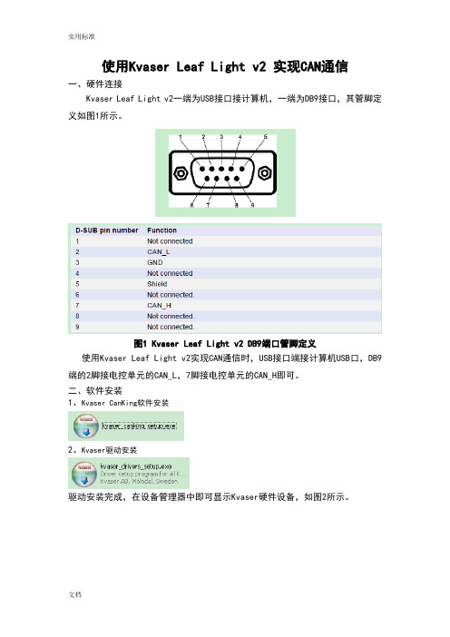
使用Kvaser Leaf Light v2 实现CAN通信一、硬件连接Kvaser Leaf Light v2一端为USB接口接计算机,一端为DB9接口,其管脚定义如图1所示。
图1 Kvaser Leaf Light v2 DB9端口管脚定义使用Kvaser Leaf Light v2实现CAN通信时,USB接口端接计算机USB口,DB9端的2脚接电控单元的CAN_L,7脚接电控单元的CAN_H即可。
二、软件安装1、Kvaser CanKing软件安装2、Kvaser驱动安装驱动安装完成,在设备管理器中即可显示Kvaser硬件设备,如图2所示。
图2 CAN Hardware(Kvaser)硬件连接成功三、Kvaser CanKing软件使用步骤1、点击电脑的“开始”选择“所有程序”里面的Kvaser CanKing,即可进入CanKing 软件,见图3:图3 Kvaser CanKing打开点击CanKing软件,弹出警告对话框,如图4所示。
图4 Kvaser CanKing打开弹出警告对话框选择OK,弹出Kvaser CanKing工程选择对话框,见图5:图5 Kvaser CanKing工程选择对话框2、选择OK,弹出Template对话框,可以选择支持单通道的测试仪或者双通道的测试仪,见图6,因为本说明中使用的是Kvaser USBcan Ⅱ,因此选择CAN kingdom(2 channels)。
图6 Template对话框3、选择OK进入到Kvaser CanKing软件界面,见图7:图7 Kvaser CanKing软件界面在CAN1设置框中的“Bus Parameters”栏中设置波特率250000bit/s,选择应用即可,如图8所示。
图8 Kvaser CanKing软件CAN1参数设置界面4、设置发送数据帧显示格式,选择Kvaser CanKing菜单栏的Options→Global,见图9所示。

Getac Diagnostic Assistant1.Introduction2.Getting Starteder manualII.System RequirementsIII.Upload report3.Contact Getac1.IntroductionGetac Diagnostic Assistant tool is one touch health check software for end user to scan Getac device key components condition (Windows 10 & 7 only). You can also get the latest BIOS, EC and utility update.Your company IT department might manage BIOS setting, please contact them before installing.Getac Diagnostic Assistant will also provide recommendation when detect any issue. User can share diagnostic report to Getac before apply service request. Service center can pre-allocated parts and engineers for you.2.Getting StartedDownload:Getac Diagnostic Assistant software is available to download from Getac web site ( ) and we will keep updating this software.I. User Manual:A.Download and unzip file, double click onGetacDiagnosticAssistant to launch software.Click “Scan” and software willautomatically show the BIOS, EC,OS information and diagnose keycomponents.B.Please check if any warning and message. If your battery is not ingood condition or need to get extra storage space, please contact your local dealerC.For other hardware issues, please apply service request viaII. System RequirementsGetac Diagnostic Assistant only works on Getac device with OS Windows 7 and 10.Available Model:A140; B300G5~G7; EX80; F110G1~G4; K120; RX10;S400G3; S410G1~G2; T800G1~G2; UX10; V110G1~G4;X500G1~G3III. Upload Report:Recommend to share diagnostic report to Getac which can make your service workflow more efficiency3.Contact GetacIf you have any question and you are very welcome to contact us via email *****************************or visit our web site https://。
发动机匹配标定方案Engine Controls and Calibration范明星应用工程师意昂神州(北京)科技有限公司北京市海淀区上地信息路26号中关村创业大厦315-326室电话:(010)8289-8056传真:(010)8278-0433电邮:Jeff.fan@提纲匹配标定的概念标定的基本流程基本标定系统的组成基本标定工具发动机标定和测量系统解决方案系统配置VISION标定和测量系统主要功能特点VISION标定和测量系统竞争优势发动机数据采集系统CSM数据采集设备介绍CSM与VISION基于CAN总线应用示意图CSM测量设备与ETAS测量设备的对比 标定过程中常用空燃比测定仪匹配标定概念发动机控制策略与OBD策略包含了上万个自由参数(单值参数,二维表格,和三维表格等)。
对于一个新的车型应用,这些自由参数需要重新调整从而使该发动机:-在各种不同的环境下运转优良:高温、高寒、高原、水平面等-满足要求的排放标准-具有优良的驾驶性-油耗最小-冷热启动稳定等标定基本流程投放生产整车验证车辆标定台架基本标定三高标定试验排放试验故障诊断标定一般情况下,标定系统都是由3部分组成:-标定软件:核心部分,标定工作全部都在其图形化界面内完成-接口硬件:提供了标定软件与ECU 及测量部分的接口通道-测量模块:提供了标定的依据基本标定系统组成标定软件:ATI VISIONThermo ScanDual ScanUSBHUB基本标定工具 主流标定软件:ATI VISIONETAS INCARA DiagRAVector CANapedSpace CalDesk针对发动机标定与测量系统解决方案的系统配置标定软件:ATI VISION接口硬件:Kvaser LAPcanII或Kvaser USBcanII, T-Connector 数据采集系统:CSM数采模块Thermo-Scan SMB/CAN (可选)Dual-Scan SMB/CAN (可选)Baro-Scan SMB (可选)Thermo-Scan MiniModule(可选)AD-Scan MiniModule(可选)Kvaser USBcan IIUSBATI VISIONPressure sensor orT-ConnectorTherno-Scan MiniModulePT-Scan MiniModuleAD-Scan MiniModuleCANTermination PlugPT100SensorK73 CableKvaser USBCAN ⅡVISION Calibration SoftwareVISION 标定和测量系统-概述系统介绍:ATI (Accurate Technologies Inc) 公司是美国的一家车载嵌入式电控系统的开发、标定与测试工具技术的知名提供商之一。

CAN总线分析仪Kvaser Linx将Kvaser Linx连接到Kvaser 现场总线上,即可分析J1587、LIN、K-Line、SWC 或 LS 总线网络,其优越的兼容性、灵活性和可靠性,极大的方便了各种总线的分析,目前市场上尚只有Kvaser Linx J1587∙Kvaser Linx LIN适用于LIN 2.0和LIN 1.x.∙Kvaser Linx J1587适用于 SAE J1587/1708.∙Kvaser Linx K-line适用于ISO 9141.∙Kvaser Linx SWC适用于SAE J2411, GMLAN.∙Kvaser Linx LS适用于ISO 11898-3 (故障容忍CAN).∙Kvaser Linx Analog I/O适用于从0到24伏的输入电压.一般特点∙塑模造的9针DSUB母连接器带大拇指螺钉∙塑模造的9针DSUB公连接器∙紧凑的塑料外壳∙适用于Kvaser的高速CAN接口∙特别适合于 Kvaser Memorator Professional, Kvaser USBcan Professional产品版本∙Kvaser Linx J1587 (Schedule for Item no. 00389-7)∙Kvaser Linx LIN (Schedule for Q1, 2007)∙Kvaser Linx K-line (Schedule for Q1, 2007)∙Kvaser Linx SWC (Schedule for Q1, 2007)Kvaser Linx LS (Schedule for Q1, 2007)CAN总线基本概念CAN 是Controller Area Network 的缩写(以下称为CAN),是ISO国际标准化的串行通信协议。
在当前的汽车产业中,出于对安全性、舒适性、方便性、低公害、低成本的要求,各种各样的电子控制系统被开发了出来。

Kvaser记录仪使用常见问题及解决方法在使用Kvaser Memorator记录仪的过程中,经常会遇到一些可能出现的问题,本文将从以下几个方面讲述Kvaser Memorator的使用和可能出现的问题。
本文使用的硬件是Kvaser Memorator Pro 5xHS,序列号 00778-9;配置软件为Kvaser Memorator Config Tool,版本 V5.11.879。
一、关于新老版本配置软件的选择老版本Kvaser Memorator(蓝白),要使用老版本的Kvaser Memorator Config Tool,版本型号为 V4.9.164。
新版本Kvaser Memorator(纯黑),要使用新版本的Kvaser Memorator Config Tool,版本型号为 V5.11.879。
注:Kvaser Memorator Config Tool可在Kvaser官网https://下载。
二、记录仪连接到电脑首先通过USB接口将记录仪连接到电脑,成功连接到电脑后,记录仪PWR灯为绿色且常亮。
1、在开始菜单中打开Kvaser Memorator Config Tool ->Kvaser Memorator Pro 5xHS;2、连接记录仪(Connect>Next->Finish);3、连接成功后的状态;连接成功后,记录仪的PWR灯和CAN通讯灯轮流闪亮。
4、查看设备信息;如果PWR灯或者CAN通讯灯异常,可点击Flash LEDs,使LED快闪,查看LED是否损坏。
三、记录仪CAN通道配置1、显示CAN 通道配置信息;2、CAN通道设置;3、在Log Configuration中添加Databases;4、添加完成后,显示数据库信息;四、下载配置1、配置完成后,将配置下载到记录仪;2、配置下载成功;3、检查配置;5、配置结果;六、记录仪验货流程记录仪验货可分为两个方面:(1)作为CAN卡进行通讯(2)作为记录仪记录存储数据。
Mindray® is a registered trademark of Shenzhen Mindray Bio-Medical Electronics Co., Ltd.FilterLine® is a U.S. registered trademark of Oridion Medical Ltd.Microstream® is a U.S. registered trademark of Oridion Medical Ltd.Nellcor™ is a U.S. trademark of Nellcor Puritan Bennett Inc.Oxiband® is a U.S. registered trademark of Nellcor Puritan Bennett Inc.Durasensor® is a U.S. registered trademark of Nellcor Puritan Bennett Inc.OxiMax™ is a U.S. trademark of Nellcor Puritan Bennett Inc.Oxisensor® is a U.S. registered trademark of Nellcor Puritan Bennett Inc.Max-Fast™ is a trademark of Nellcor Puritan Bennett Inc.miniMediCO2® is a trademark or registered trademark of Oridion Medical Ltd.LNCS® is a U.S. registered trademark of Masimo Corp.LNOP® is a U.S. registered trademark of Masimo Corp.Masimo SET® is a U.S. registered trademark of Masimo Corp.Panorama™ is a U.S. trademark of Mindray, Inc.Edwards Vigilance® is a U.S. registered trademark of Edwards Lifesciences LLCCamino® is a registered trademark of Integra LifeSciences Corporation.Somanetics® and INVOS® are registered trademarks of Covidien.Copyright © Mindray DS USA, Inc., 2011-2016. All rights reserved. Contents of this publication may not be reproduced in any form without permission of Mindray DS USA, Inc.Table of ContentsForeword (xv)Warnings (xvi)Cautions (xxii)Notes (xxvi)Indications for Use (xxvii)Applied Parts (xxvii)Unpacking Information (xxviii)Warranty Statements (xxviii)Exemptions (xxix)Service (xxix)Manufacturer’s Responsibility (xxix)Company Contact (xxx)Symbols and Descriptions (xxxi)General Product Description.....................................................................................................................................1-1 General Product Description .............................................................................................................................................................................................1-2 V Series Monitoring Platform..................................................................................................................................................................................1-2Interfacing......................................................................................................................................................................................................................1-2 Key Features.............................................................................................................................................................................................................................1-3 V 12/V 21 Physical Views....................................................................................................................................................................................................1-4 Front View......................................................................................................................................................................................................................1-4Rear View........................................................................................................................................................................................................................1-6Left Side Panel..............................................................................................................................................................................................................1-8Right Side Panel...........................................................................................................................................................................................................1-9 V Dock Physical Views...........................................................................................................................................................................................................1-10 Back View........................................................................................................................................................................................................................1-10Right Side View.............................................................................................................................................................................................................1-11Left Side View................................................................................................................................................................................................................1-11VPS Physical Views......................................................................................................................................................................................................1-12 Getting Started...........................................................................................................................................................2-1 Introduction.............................................................................................................................................................................................................................2-2 Powering Unit On/Off...........................................................................................................................................................................................................2-2 Using the V 21 Touch Pad...................................................................................................................................................................................................2-3 Main Display.............................................................................................................................................................................................................................2-3 System Status Message.............................................................................................................................................................................................2-5Navigation Area...........................................................................................................................................................................................................2-6 Dialogs........................................................................................................................................................................................................................................2-8 List Box............................................................................................................................................................................................................................2-9 Alarm Icons and Messages..................................................................................................................................................................................................2-10 Alarm Icons....................................................................................................................................................................................................................2-10Parameter Messages..................................................................................................................................................................................................2-10 Keyboard Dialog.....................................................................................................................................................................................................................2-11 Using the Keyboard....................................................................................................................................................................................................2-11 Digital Keypad Dialog...........................................................................................................................................................................................................2-12 Using the Digital Keypad..........................................................................................................................................................................................2-12 Message Dialogs.....................................................................................................................................................................................................................2-12 Audio Levels Dialog...............................................................................................................................................................................................................2-13 Configuring Audio Levels.........................................................................................................................................................................................2-14 Battery Levels Dialog.............................................................................................................................................................................................................2-14 Battery Indicator Colors.............................................................................................................................................................................................2-15 System Information...............................................................................................................................................................................................................2-15 Display Setup..............................................................................................................................................................3-1 Introduction.............................................................................................................................................................................................................................3-2Table of ContentsDisplay Options Dialog.........................................................................................................................................................................................................3-2 Navigating to the Display Options Dialog..........................................................................................................................................................3-2Configuring Display Presets....................................................................................................................................................................................3-4Editing a Display Preset.............................................................................................................................................................................................3-9Locking/Unlocking Presets......................................................................................................................................................................................3-10 Temporarily Editing a Locked Display Preset....................................................................................................................................................3-11 Restoring a Temporary Preset.................................................................................................................................................................................3-12 Copying and Pasting a Display Preset.................................................................................................................................................................3-12 Renaming a Preset......................................................................................................................................................................................................3-13 Renaming an Empty Preset......................................................................................................................................................................................3-13 Deleting a Preset..........................................................................................................................................................................................................3-14 Overlapping Waveform.............................................................................................................................................................................................3-14 Changing IBP Waveform Overlap Settings.........................................................................................................................................................3-15 Undoing an IBP Waveform Overlap......................................................................................................................................................................3-15 Displaying NIBP Digital Tile in Large Font..........................................................................................................................................................3-16 Privacy Mode.................................................................................................................................................................................................................3-17 Screen Lock Mode.......................................................................................................................................................................................................3-17 Standby Mode..............................................................................................................................................................................................................3-17 Discharge Mode...........................................................................................................................................................................................................3-17 View All ECG Mode......................................................................................................................................................................................................3-17 Changing Lead/Size....................................................................................................................................................................................................3-18 Touch Screen Calibration.........................................................................................................................................................................................3-18 Display Options Troubleshooting....................................................................................................................................................................................3-20 Mechanical Functions.................................................................................................................................................4-1 Introduction.............................................................................................................................................................................................................................4-2 V 12..............................................................................................................................................................................................................................................4-2 V 12 Docking.................................................................................................................................................................................................................4-2V 12 Undocking............................................................................................................................................................................................................4-3Battery Installation......................................................................................................................................................................................................4-4Battery Removal...........................................................................................................................................................................................................4-6Battery Charge Checking..........................................................................................................................................................................................4-8Module Installation.....................................................................................................................................................................................................4-9Module Indicator Lights............................................................................................................................................................................................4-10 Module Removal..........................................................................................................................................................................................................4-11 V Dock.........................................................................................................................................................................................................................................4-12 V Dock Mounting.........................................................................................................................................................................................................4-12 V Dock Dismounting..................................................................................................................................................................................................4-14 V 21..............................................................................................................................................................................................................................................4-15 V 21 Docking.................................................................................................................................................................................................................4-15 V 21 Undocking............................................................................................................................................................................................................4-16 V Hub..........................................................................................................................................................................................................................................4-17 V Hub Mounting...........................................................................................................................................................................................................4-17 V Hub Dismounting....................................................................................................................................................................................................4-17 Module Installation.....................................................................................................................................................................................................4-17 Module Removal..........................................................................................................................................................................................................4-18 Module Locking...........................................................................................................................................................................................................4-19 Module Unlocking.......................................................................................................................................................................................................4-19 V Hub Status Indicators.............................................................................................................................................................................................4-20 Connecting the V Hub to the V 12/V 21..............................................................................................................................................................4-21 Rolling Stand............................................................................................................................................................................................................................4-23 Thermal Recorder...................................................................................................................................................................................................................4-26 Installing the Thermal Recorder Paper................................................................................................................................................................4-26Table of ContentsMechanical Functions Troubleshooting........................................................................................................................................................................4-28 Module Configuration................................................................................................................................................5-1 Module Status Dialog............................................................................................................................................................................................................5-2 Navigating to the Module Status Dialog............................................................................................................................................................5-3Enabling/Disabling a Module..................................................................................................................................................................................5-3Changing an IBP or Temperature Module Channel........................................................................................................................................5-3Changing VDI Modes.................................................................................................................................................................................................5-4V 12/V 21 V Hub Module Limitations...................................................................................................................................................................5-5V 12/V 21 Module Limitations.................................................................................................................................................................................5-5 VPS Synchronization.............................................................................................................................................................................................................5-6 Buttons on VPS.............................................................................................................................................................................................................5-6VPS Synchronization: Mismatched Patient IDs.................................................................................................................................................5-6VPS Synchronization: Same Patient IDs...............................................................................................................................................................5-7VPS Synchronization Failures..................................................................................................................................................................................5-7 Module Configuration Troubleshooting........................................................................................................................................................................5-8 Patient Management..................................................................................................................................................6-1 Introduction.............................................................................................................................................................................................................................6-2 Patient Info Dialog.................................................................................................................................................................................................................6-2 Navigating to the Patient Info Dialog..................................................................................................................................................................6-2Admitting a Patient.....................................................................................................................................................................................................6-3Patient Demographics ..............................................................................................................................................................................................6-3Patient Room and Bed...............................................................................................................................................................................................6-5Discharging a Patient.................................................................................................................................................................................................6-6Clearing Patient History............................................................................................................................................................................................6-7Placing a Patient in Standby....................................................................................................................................................................................6-7Exiting the Standby Mode........................................................................................................................................................................................6-7 Patient Management Troubleshooting..........................................................................................................................................................................6-8 Alarm Behavior...........................................................................................................................................................7-1 General Alarm Behavior.......................................................................................................................................................................................................7-2 Physiological Alarms.............................................................................................................................................................................................................7-2 Alarm Behaviors...........................................................................................................................................................................................................7-2Alarm Options...............................................................................................................................................................................................................7-2Physiological Alarm Responses..............................................................................................................................................................................7-3 Technical Alarms.....................................................................................................................................................................................................................7-4 Alarm Behaviors...........................................................................................................................................................................................................7-4 Alarms .........................................................................................................................................................................8-1 Alarms ........................................................................................................................................................................................................................................8-2 Navigating to the Alarms Dialogs..........................................................................................................................................................................8-2 Alarm Limits..............................................................................................................................................................................................................................8-2 Configuring Alarm Limits..........................................................................................................................................................................................8-2Factory Default Alarm Limits...................................................................................................................................................................................8-5Auto-Set All Alarms Button......................................................................................................................................................................................8-10Restore All Defaults Button......................................................................................................................................................................................8-10 Alarm Responses....................................................................................................................................................................................................................8-11 Understanding Alarm Levels...................................................................................................................................................................................8-11Characteristics of Visual Alarm Signals................................................................................................................................................................8-11Factory Default Alarm Priorities between Alarm Types.................................................................................................................................8-11Configuring Alarm Levels.........................................................................................................................................................................................8-13Understanding Alarm Response Settings...........................................................................................................................................................8-13Configuring Alarm Response Settings.................................................................................................................................................................8-13Factory Default Alarm Settings...............................................................................................................................................................................8-14 Arrhythmia Alarms.................................................................................................................................................................................................................8-17。
Kvaser MemoratorProfessional User's GuideCopyright 2001-2006 Kvaser AB, Mölndal, SwedenLast updated Tuesday, 07 November 2006We believe that the information contained herein was accurate in all respects at the time of printing. Kvaser AB cannot, however, assume any responsibility for errors or omissions in this text. Also note that the information in this document is subject to change without notice and should not be construed as a commitment by Kvaser AB.(This page is intentionally left blank.)1 Table of Contents1About this manual (4)2Introduction (5)2.1Welcome to Kvaser Memorator Professional (5)2.2Major features of Kvaser Memorator Professional (6)2.3CAN logger Functions (6)2.4Real time CAN-USB interface (7)2.5Kvaser Memorator Professional setup tool (7)2.6Additional software and documentation (7)3Kvaser Memorator Professional hardware (8)3.1Hardware installation (8)3.2USB connector (8)3.3CAN channels (8)3.4Power supply (10)3.5Flash disks (10)3.6LED indicators (11)3.7External trigger input (14)3.8External trigger output (15)4How to use the Kvaser Memorator Professional (17)4.1Use as a CAN interface (17)4.2Configure for logging (17)4.3Use as a logger (17)4.4Kvaser Memorator Professional setup tool (17)4.5Disk management (18)4.6Troubleshooting (18)5Appendices (19)5.1System requirements (19)5.2Technical data (19)5.3Performance comparison (20)5.4Disk capacity (21)5.5Disk structure (21)5.6CAN connectors (21)5.7Updating the firmware (23)5.8Required driver version (24)5.9Write protection switch (24)5.10CAN bus termination (25)5.11CAN bus overrun (25)5.12Daisy-chaining several interfaces (25)6Frequently Asked Questions (26)7Legal acknowledgements (27)7.1Usage warning (27)7.2EMC compliance statement (28)7.3WEEE compliance statement (28)7.4RoHS compliance statement (28)7.5Patents, copyrights and trademarks (28)8Document revision history (29)2 About this manualThis manual is intended for the Kvaser Memorator Professional users. This manual contains a description of the hardware’s properties and general instructions for connecting the device to a computer. The setup software for the Kvaser Memorator Professional is called the Kvaser Memorator Professional Setup Tool and is described in detail in its online help.3 IntroductionThis section will describe the functions and features of the Kvaser Memorator Professional. 3.1 Welcome to Kvaser Memorator ProfessionalFigure 1. Kvaser Memorator Professional.Kvaser Memorator Professional is a small, yet advanced portable CAN data logger. The device can be configured in many different ways to achieve the most suitable and effective logging for any occasion. Connecting the logger to a PC provides direct access for configuring baud rates, trigger conditions and filters using the standalone setup tool. You can use standard SD or MMC flash disks. These memories are robust, inexpensive and small – about the size of a stamp.Kvaser Memorator Professional can also be used as a powerful two channel real time CAN to USB interface – two products in one!Using the included software Kvaser Dispatcher you can package a complete logging measurement setup and send it to a remote location where the staff can use the self installing, easy to use package to carry out the logging and send the data back home, without having to do any complicated setup or configuration. Just plug and play!An additional advantage of the Kvaser Memorator Professional is that in the near future it will be possible to log traffic on J1587, LIN, SWC, and K-line networks as well. By connecting the flexible Kvaser Linx to your Kvaser Memorator Professional, or through on-demand customized integrated solutions, you will get an even more powerful and versatile data logger. This guide is applicable to the Kvaser Memorator Professional devices listed in Table 1.Table 1: The Kvaser Memorator Professional device and its EAN number.Device Product NumberKvaser Memorator Professional HS/HS 733-0130-00351-43.1.1 TriggersLog continuously or create triggers to control when frames are logged. You can create up to 16 trigger conditions. These conditions can include the reception of a specific message, the condition of a specific signal in a message, or an external trigger input configured to trigger on either rising or falling edge. Define a posttrigger time to control the amount of data logged after the trigger expression becomes false. Define a pretrigger time to log events leading up to the trigger expression becoming true.3.1.2 FiltersTo enhance logging performance, Kvaser Memorator Professional can filter out selected messages to be logged. The identifiers to be filtered can be picked from a database file or entered manually. Three types of filters are provided: stop filters, pass filters, and counting pass filters. Stop filters prevent messages from being logged. Pass filters ensure a message is logged. Counting pass filters log the specified messages at enumerated occurrences so redundant data is reduced.3.1.3 Memory cardsAny standard SD or MMC type flash memory card can be used. SDHC cards will be supported by an upcoming firmware upgrade. The maximum size is currently 2 GB.3.2 Major features of Kvaser Memorator Professional• CAN interface and data logger – two products in one• Quick and easy plug-and-play installation.• Supports both 11-bit (CAN 2.0A) and 29-bit (CAN 2.0B active) identifiers.• CAN messages are time-stamped with 2 microseconds resolution.• Large on-board RAM buffer for CAN messages.• Supports silent (listen-only) mode for analyzing tools and data logging.• 100% compatible with applications written for Kvaser hardware such as LAPcan, PCIcan, and USBcan with Kvaser CANLIB.• Two high-speed CAN connections (compliant with ISO 11898-2), 5 kbit/s up to 1 Mbit/s.• Fully compatible with J1939, CANopen, NMEA 2000® and DeviceNet.• One USB 2.0 HiSpeed connection with data rates up to 480 Mbit/s. The device can also be used in USB 1.1 slots (with up to 12 Mbit/s).• Power is taken from the CAN bus or from the USB bus. The device automatically switches power supply between the CAN (primary) and the USB (secondary),reducing power drain on a laptop’s battery.• Small, light plastic housing with dimensions (W x L x H) approximately 46 x 115 x 22 mm (1.8 x 4.5 x 0.9 inch) – easy to tuck away (e.g. in a vehicle during a test drive)3.3 CAN logger Functions• One flash disk connector that accepts SD and MMC cards, with the size ranging from32 MB up to 2 GB.• SDHC cards will be supported by an upcoming firmware upgrade. It is expected that SDHC cards with a capacity of 32 GB will be available within the foreseeable future.• Built-in real time (calendar) clock with battery backup.• Easy to use graphic configuration tool• Logger status is indicated with five externally visible LEDs.• Supports silent mode – log bus traffic without interfering with it.• Handles 100% bus load at 1 Mbit/s with two channels (>20000 messages per second)• Starts up in 60 milliseconds.• Upload logged data via USB at 1.2 MB/s when connected via USB 2.0 HiSpeed, or at14 MB/s when using an external flash disk reader.• External trigger input (e.g. pushbutton)• External trigger output (e.g. a LED or buzzer)• Pretrigger space is limited by available disk space only• Select trigger signals from a CAN database, or define them directly in the setup tool 3.4 Real time CAN-USB interface• Uses USB 2.0 HiSpeed, while maintaining compatibility with USB 1.x computers.• Supports extreme data throughput, quick reaction times and precise time stamping – removing any bottlenecks. Handles up to 40 000 messages per second.• Kvaser MagiSync - automatic time synchronization between all Kvaser products that uses the Kvaser MagiSync feature.• Supports silent mode for analyzing tools – listen to the bus without interfering with it.• Simultaneous operation of multiple devices.• Power supplied through the CAN bus interface or through the USB interface.3.5 Kvaser Memorator Professional setup tool• Easy to use graphic configuration tool• File manager for organizing and converting log files to a variety of formats, including CSV, ASCII, MDF and Matlab formats• Configuration of the CAN controller (bit rate and filters).• Configuration of the trigger conditions.• Configuration of message filters which controls the messages stored.• The configuration is downloaded via USB.• Using the included Kvaser Dispatcher software, a complete measurement setup can be turned into a self-installing package that is shipped to a remote location to carryout a specific logging task.3.6 Additional software and documentation• Kvaser CANLIB SDK, which includes everything you need to develop software for the Kvaser CAN hardware. Includes full documentation and many sample programs,written in C, C++, C#, Delphi, and Visual Basic. All Kvaser CAN interface hardwareshares a common software API. Programs written for one board type will run without modifications on the other board types!• On-line documentation in Windows® HTML Help and Adobe Acrobat format.• Documentation, software and drivers can be downloaded for free at or purchased separately on CD if preferred.4 Kvaser Memorator Professional hardwareIn this section you can read more about the CAN channels, power supply, flash disks, led indicators, and external triggers.4.1 Hardware installationThe Kvaser Memorator Professional may be inserted in any free USB socket on the host computer. You do not need to switch the power off before inserting or removing the device. For the Kvaser Memorator Professional to communicate with the host computer, the correct version of the Kvaser driver and firmware must be installed. The firmware is downloaded and installed directly on the Kvaser Memorator Professional and the driver is installed on the host computer. For additional information on how to upgrade the firmware, read section 6.7, Updating the firmware.The delivery package of Kvaser Memorator Professional contains:• Kvaser Memorator Professional.• Software and Driver CD, containing drivers for Windows; Kvaser Memorator Professional Setup Tool; Kvaser CANKing, an easy to use CAN bus monitor; Drivers for RP1210A, LabView and DIAdem; and Kvaser CANlib Software Development Kit.• Kvaser Memorator Professional User's Guide.• USB cable.• SD card.For driver installation information, see the driver and hardware installation guide which can be found at .4.2 USB connectorThe Kvaser Memorator Professional has a standard USB type “B” receptacle connector. Connect it to your PC using any high quality, USB 2.0 certified cable. The maximum USB cable length is 5 meters (approx. 16.5 ft.). If you need a longer cable, you can use USB hubs or USB extension cables with a built-in hub. By chaining up to 5 hubs, you can achieve a cable length of up to 25 meters (approx. 83 ft.)4.3 CAN channelsThe standard Kvaser Memorator Professional has two independent CAN channels that are seen in Figure 2. The first CAN channel is marked on the housing with the symbol ‘1’, where as the second channel (number 2) is not marked. See Figure 3. The CAN connectors are also labeled for easy identification.CAN channel connectorsUSB device connectorFigure 2: Connections on the Kvaser Memorator Professional. The two CAN channels are to the left and the USB device connector is to the right.Figure 3: The CAN channels on Kvaser Memorator Professional.4.4 Power supplyThe Kvaser Memorator Professional can be powered from the CAN side and from the USB side. To operate the Kvaser Memorator Professional in logger mode, you must supply power on the CAN side. To use the device as a CAN interface, or to configure the device for logging, it is sufficient to supply power from the USB side.When you supply power on the CAN side, provide power on the channel 1 connector. Use pin 9 for V+ and pin 3 for ground. The supply power should be in the range of 6 – 35 V DC. The power requirement is around 1 W (maximum). It is safe, but pointless, to supply power on channel 2. The device will tolerate a higher input voltage, up to 48 V DC.4.5 Flash disksYou can use SD (Secure Digital) or MMC (MultiMediaCard) disks with your Kvaser Memorator Professional. SDHC (Secure Digital High Capacity) disks are not supported as of this writing (September 2006.)The following disk sizes are supported and have been tested:Table 2: Supported disks.MMC 32 MB – 1 GBSD 32 MB – 2 GBSDHC To be supported in a free future firmware releaseIMPORTANT: not all disks follow the MMC or SD standard. When in doubt, consultour web site for a list of recommended disk types.Insert the flash disk into the slot of the Kvaser Memorator Professional(see Figure 4) with the disk’s golden connector side up. Do not apply excessive force. The disk should slide smoothly into the socket. When fully inserted, the disk should fit well within the slot.Before removing the disk, we recommend that you either• Connect the device to a PC via USB, or• Remove the power completely (that is, disconnect both CAN 1 and CAN 2.)Figure 4: How to insert a memory card.4.6 LED indicatorsThe LED indicators (see Figure 5) have somewhat different meaning depending on how your Kvaser Memorator Professional is being used – as a CAN interface or as a CAN logger. The following tables describe how the LEDs behave in these two cases.Table 3: LED indicators overview.Lamp General meaningPWR (Green) Power and general status.CAN 1 (Yellow) Status for CAN channel 1.CAN 2 (Yellow) Status for CAN channel 2.ERR (Red and yellow) Indicates temporary or permanent errors.Note that the ERR lamp is bi-colored and can be both red and yellow.Figure 5. LEDs on the Kvaser Memorator Professional. Table 4: LED indicators when used as a CAN interface.PWR (Green) CAN 1(Yellow)CAN 2(Yellow)ERR(Red)MeaningSlow flash Waiting for USB connection with the PC.SteadyPower ON (The device is connected tothe computer).Short flash CAN traffic on channel 1.Short flash CAN traffic on channel 2.Blink CAN 1 error passive.Blink CAN 2 error passive.Steady CAN 1 bus off.Steady CAN 2 bus off.ShortflashError frame on either channel.SteadySelf-test failed, wrong bit rate, CAN bustransceiver failure.Fast flash Firmware configuration error (should not normally happen, so please contact the support).Table 5: LED indicators when the device is used as a logger.CAN statusCAN1/CAN2 emitting short flashes:CAN messages are sent or receivedCAN1/CAN2 blinking and ERR blinking red:The CAN channel is error passiveCAN1/CAN2 blinking slowly and ERR blinking slowly red:The CAN channel is bus offERR emitting short yellow flashes:Error frames are received on CAN1 or CAN2Error conditionsERR constant red with one yellow flash:CAN overrunERR constant red with two yellow flashes:Disk fullERR constant red with three yellow flashes:Configuration file missing or corruptERR constant red with four yellow flashes:Disk errorERR constant red with five yellow flashes:Some other major error; please contact the supportLogging statusPWR 90% on and 10% off:Everything OK; logging started without problems. The device is “armed” and waiting fora trigger.PWR flashing:Everything OK, logging is active and actively logging trafficPWR blinking slowly 50/50:Logging has stopped due to a trigger condition and Kvaser Memorator Professional isoff bus.When connected to the setup tool“Running lights”:The device is communicating with the setup toolERR blinking red:Disk activity such as formattingOther blink patternsAll lamps blinking slowly:Disk is missing or improperly inserted, and no USB communication is detected.Check the disk or the USB connection.PWR emits a flash every few seconds; the other lamps are dark:No USB communication. Check USB cables and communication. Unplug thedevice and reconnect it after a few seconds. Check that the device driver isinstalled correctly.PWR flashing, ERR constant red:Firmware configuration error. This should not normally happen. Please contactthe support.4.7 External trigger inputThe Kvaser Memorator Professional can be set up to trigger on an external signal. There are two ways to create this signal:• Connect a switch from pin 4 on CAN channel 1 to ground, which can be found on pin3 on the same connector. See Figure 7.• Connect a signal between 0 and 5 V to pin 4 on CAN channel 1.Internally, pin 4 on CAN channel 1 has a pull-up to +5V. See Figure 6.The trigger can be configured to react on both falling and rising edges.• If it is set to trigger on a falling edge, the trigger is activated when pin 4 is connected to ground.• If it is set to trigger on a rising edge, the trigger is activated when pin 4 is disconnected from ground.Figure 6: The trigger input inside the Kvaser Memorator Professional.Figure 7: How to connect an external trigger switch.4.8 External trigger outputIt is also possible to send an external pulse through channel two’s CAN connector pin 4 on the Kvaser Memorator Professional. For further information on how to configure the Kvaser Memorator Professional to send an external pulse, please refer to the Kvaser Memorator Professional setup tool online help.Figure 8: The trigger output inside the Kvaser Memorator Professional.Figure 9: Sample circuit for connecting a LED to the trigger output.5 How to use the Kvaser Memorator ProfessionalThe Kvaser Memorator Professional can operate both as a high performance real time USB interface (USB-CAN mode) and as a data logger (logger mode). This section will describe how to use the different modes.5.1 Use as a CAN interfaceTo use the Kvaser Memorator Professional as a CAN interface; connect the unit to a free USB socket on your PC or USB hub. You do not need to insert a flash disk. If a flash disk is inserted, you do not need to remove it.When used as a CAN interface, the green lamp will be illuminated and the yellow lamps will emit short flashes when CAN messages are transmitted and received.5.2 Configure for loggingTo prepare your Kvaser Memorator Professional for logging:1. Connect the unit to a free USB socket on your PC or USB hub.2. Insert a flash disk (see Figure 4 above)3. Start the setup program and press the Connect button.The device should immediately show a running light pattern on the LEDs.5.3 Use as a loggerTo use your Kvaser Memorator Professional as a logger:1. Insert a formatted flash disk that contains a valid configuration2. Optionally, connect an external trigger switch to the CAN1 connector3. Optionally, connect the digital output pin on the CAN2 connector to your equipment4. Supply power on the CAN1 connectorLogging should start immediately.If everything is OK, the green PWR lamp should either blink quickly, or beilluminated 90% and dark 10% of the time. If CAN traffic is detected, the CAN1 and CAN2 lamps should be illuminated.5.4 Kvaser Memorator Professional setup toolTo log CAN traffic with the Kvaser Memorator Professional, you need to create and download a configuration to the device. The Kvaser Memorator Professional needs to be in USBcan mode, that is, insert a disk and connect the USB cable. Start the PC application KvaserMemorator Professional setup tool and press the Connect button in the tool bar. If the LEDs on Kvaser Memorator Professional are flashing in a “running light” pattern, the device is ready to communicate with the setup tool.For further information about the setup tool please refer to its online help.5.5 Disk management• Handle the disks with care. They are robust, but better safe than sorry.• Avoid removing the disk when the device is powered up from an external power source. You should first remove the external power and then remove the disk. If thedevice is connected via USB, you should make sure the setup tool isn’t writing to the disk before you remove it.• You may remove and reconnect the disk, the external power and the USB in any order you like without damaging the hardware. But if you follow the advice above,you will not damage your precious logged data.• If you need to remove the disk when the device is being used as a logger and you can’t disconnect the external power, try to connect the USB cable to a running PCfirst. When the Kvaser Memorator Professional discovers the active USB connection, the device will stop logging and close the log file in an orderly fashion.5.6 Troubleshooting• Use “Kvaser Hardware” in the Control Panel to verify that the computer really can talk to the Kvaser Memorator Professional. Read out the firmware version.If it’s all zeroes, there are communication problems.• Verify that the disk is formatted. If in doubt, reformat it using the Kvaser Memorator Professional setup tool.• If configuration fails, verify that the Kvaser Memorator Professional is in configuration mode when you are using the setup tool. You can see this bylooking at the LEDs – they should flash in a “running light” fashion.• If the LEDs are flashing or glowing, compare the pattern with the specified led indicators in Table 4 and Table 5.• If the LEDs are not flashing or glowing at all, check the power supply.6 AppendicesIn this section you will find technical information about Kvaser Memorator Professional and its connectors.6.1 System requirements• A USB interface. Use USB 2.0 HiSpeed for optimum results, although the device will work with a USB 1.1 interface too.• Operating system Windows ME, Windows 2000, Windows XP, Windows Server 2003, Windows Vista.6.2 Technical dataIn Table 6 below you will find the Kvaser Memorator Professional’s technical specifications. Table 6: Kvaser Memorator Professional Technical specifications.CAN Channels 2 (CAN 2.0A and 2.0B active).CAN Transceivers SN 65251 (Compliant with ISO 11898-2)CAN Controller Built into the M32CMicrocontroller Renesas M32CCAN Bit Rate 5 kbit/s to 1 Mbit/sTimestamp resolution 2 sError Frame Detection Yes, both channels.Error Frame Generation Yes, when used as a USB-CAN interface.PC interface USB 2.0. Supports HiSpeed (HS) at 480 Mbit/patible with USB 1.1 at 12 Mbit/s.Power consumption ~ 5V and 130mA if powered from the USB and ~ 850mW if powered from the CAN bus.External power Pin 9 (V+) and pin 3 (GND) on CAN channel 1.Allowed operating voltage 6 – 35 V DC. Maximum input voltage 48 V DC.Software requirements Windows 2000, Windows XP, Windows Server 2003, Windows Vista, Windows 98, Windows ME. – Supported as CAN interface on Linux 2.6 and Windows CE 4.2 and 5.0.Hardware configuration Done by software (Plug & Play). Dimensions (W x L x H) 46 x 115 x 22 mm (1.8 x 4.5 x 0.9 inch) Operating temperature -40 ºC ... +85 ºCWeight 142 g including cables and connectors. Storage temperature -40 ºC ... +85 ºCRelative Humidity 0% ... 85% (non-condensing.)External trigger Available on CAN connector 1 pin 4. The input is protected by a self-healing fuse and has a 1 kOhm pull-up to +5V. The firmware can detect both rising and falling edges.The allowed voltage is 0 – 5 V DC.External output Available on CAN connector 2 pin 4. The output is a pull-down to ground and is protected by a self-healing fuse. The allowed voltage is 0 – 5 V DC.6.3 Performance comparisonIn Table 7 below the performance of the Kvaser Memorator Professional is compared with its older sibling, the Kvaser Memorator.Table 7: Performance comparison.Kvaser Memorator Professional Kvaser MemoratorRX performance perchannel (when used asa CAN interface).20000 messages/s 12000 messages/sTX performance perchannel (when used asa CAN interface).20000 messages/s 6000 messages/sLogging performance 20000 messages/s 5000 messages/sTime stamp accuracy. 2 µs 100 µsMessage filter support. Stop filtersPass filtersCounting filtersPass filtersSD memory sizesupport.Currently 2 GB 1 GB SDHC memory support With upcoming free firmware update No Galvanic isolation. Yes No Number of triggers. 16 8Startup time when usedas a logger< 0.25 seconds 2.5 secondsUpload of logged data 1.4 MB/s (when connected via USB2.0 HiSpeed)15 MB/s (when using an external disk reader)6.4 Disk capacityEach CAN message occupies 24 bytes in the log file. The following table gives some approximate values of the capacity for various disk sizes.Table 8: Disk capacity.Disk size Approximate capacity Approximate time to fill the disk (at 500 messages per second)64 MB 2,700,000 messages 1h 30min 256 MB 10,700,000 messages 6h 512 MB 21,300,000 messages 12h 1 GB 41,700,000 messages 23h 2 GB83,300,000 messages46h 30min6.5 Disk structureYou can use an external card reader to read the files on the flash disk. The KvaserMemorator Professional setup tool can read the log data directly via the external card reader, so you don’t need to copy the files to your hard disk.Note: It is essential that the flash disks be formatted using the Kvaser Memorator Professional setup tool. You should not copy any files to the disk using an ordinary flash disk writer. The setup tool will create two special files on the disk. These files must be contiguous and the structure and position of these files must be determined by the firmware, or the data logging will fail.The Kvaser Memorator Professional setup tool will create the following two files on the flash disk when formatting it:Volume in drive G is unlabeled Directory of G:\*63,183,872 LOGDATA.KMF 4,096 PARAM.LIF63,187,968 bytes in 2 files and 0 dirs 63,187,968 bytes allocated 0 bytes freeLOGDATA.KMF will by default occupy nearly the whole disk – in this case a 64 MB disk – regardless of whether the file contains any logging data or not. PARAM.LIF will occupy the rest of the disk.6.6 CAN connectorsThe Kvaser Memorator Professional has two high-speed CAN channels. Both CAN channels have 9-pin D-SUB connectors (see Figure 10) with the pinning described below (see Table 9 and Table 10).Figure 10: The D-SUB connector pin numbers on a CAN channel. Table 9: D-SUB pin configuration of the CAN channel 1.The CAN channel 1 has the following pin configuration.(Auto-reset fuses protect Pins 2, 3, 4, 7 and 9.)D-SUB pin number Color code Function1 N/A Not connected.2 Green CAN_L3 Brown GND4 Orange External trigger input.5 Black Shield6 N/A Not connected.7 Red CAN_H8 N/A Not connected.9 Yellow Power supply to the device. Table 10: D-SUB pin configuration of the CAN channel 2.The CAN 2 channel has the following pin configuration.(Auto-reset fuses protect Pins 2, 3, 4, 7 and 9.)D-SUB pin number Color code Function1 N/A Not connected.2 Green CAN_L3 Brown GND4 Orange External trigger output.5 Black Shield6 N/A Not connected.7 Red CAN_H8 N/A Not connected.9 Yellow Not connected.。
Kurzweil 3000 for Macintosh Getting Started GuideKURZWEIL 3000 PRODUCTS (3)OPEN KURZWEIL 3000 (4)Web License (4)Desktop Client - Standalone (4)Tip Of The Day (4)Offline Mode (4)ACCESS CONTENT (5)File Menu (5)Starting Points Menu (5)The Universal Library - Web License (5)Google Drive (5)Images of Printed Material (6)From Online File Storage - (6)From a Scanner (connected to your computer) (6)Virtual Print (6)STARTING POINTS (7)PALETTES (8)Reading Palette (8)Tools Palette (10)TOOLBARS (12)Manage Toolbars (12)Reading Toolbar (12)Studying Toolbar (13)Writing Path Toolbar (14)Document Prep Tools (16)Other Tools (17)DON’T FORGET TO SAVE! (18)RESOURCES (18)Kurzweil 3000 Universal LibraryAdd to Chrome or Firefox web browsers for Text to Speech (TTS) access to content on the flyWEB LICENSEYour username and password are the same for ALL Kurzweil 3000 Web License Subscriptioncomponents.If you are the Kurzweil site administrator– login is emailed to you in your welcome package from Kurzweil’s Customer Service team.If you are a teacher or student– check with your school/district Kurzweil site administrator to obtain your username and password.Universal Library is accessible in Web, Windows, and Mac versionsDESKTOP CLIENT - STANDALONEDouble Click the Kurzweil 3000 icon on your desktop, dock or Applications folder.TIP OF THE DAYThe Tip of the Day will automatically open with a different tip.You can click Previous, Next or Random to see other tips.OFFLINE MODEIf no internet connection is detected when you launch Kurzweil 3000 Web License, you may still be able to use Kurzweil 3000 in Offline Mode.You’ll need to have previously logged into Kurzweil 3000 Web License on your machine with internet access within your subscription’s Offline Mode duration for this to be available.FILE MENUKurzweil 3000 can open a variety of files and convert them to .kes files.From your local Computer, the Universal Library, or Google Drive•File > Open…, Open from Universal Library, or Open from Google Drive STARTING POINTS MENUFrom here you can:•Open a New draft document•Open an existing file from your local computerTHE UNIVERSAL LIBRARY - WEB LICENSEUnlimited cloud storage for your Kurzweil 3000 files in addition to some pre-loaded content:•Your Private and Public folders•Public folders for the Top Level admin and any teachers or students in yourteam. Students cannot see other student’s folders.•Classic Literature folder (1800+ titles)•Help files folder•Non-Fiction Bookbag folder containing 15 titles for grades 3 through 8•Sample files folder•TemplatesClick on the toggle arrow next to a folder to expand itClick on the folder where the file is savedChoose the file from the list on the rightGOOGLE DRIVE•File > Open from Google Drive•Click the Sign In button if you are not already signed into Google Drive•Locate your file and click OpenIMAGES OF PRINTED MATERIAL•PICTURES OF PAGES, FROM CELL PHONE, ETC.o Save (or upload) image to Google Drive or your local computero Open the image using File > Open… or Open from Google DriveFROM ONLINE FILE STORAGE -•SUCH AS DROP BOX, ONE DRIVE, BOX, ETC.o Download the file to your computer from the online storage program (such as Dropbox)o Use File > Open, to locate the fileFROM A SCANNER (CONNECTED TO YOUR COMPUTER)•(CONNECTED TO YOUR COMPUTER)o Choose Scan >Scan New DocumentVIRTUAL PRINT•BRING FILES FROM ANOTHER APPLICATION INTO KRUZWEL 3OO TO SAVE AS A .KES FILE o Open a file in its native applicationo File > Printo In the PDF dropdown, choose Open as a PDF in Kurzweil 3000o The file will appear in KURZWEIL 3000 to be read, saved, etc.Different toolbars and palettes will be available based on the type of document you are in.DETAILSPlace cursor where you want to startToggle Reading Audio Reading SpeedTOOLS PALETTEHighlight, Circle orCross-out textMANAGE TOOLBARS• Select a desired Toolbar• Double click on a Toolbar to Customize • Choose from the options in the popup window, •Choose Toolbar formatREADING TOOLBARSTUDYING TOOLBARWRITING PATH TOOLBARDOCUMENT PREP TOOLSOTHER TOOLSYou can save files to your local computer, a local network folder, Save a copy to Google Drive, and the Universal Library (Web License Subscription Only).The Kurzweil AcademyNew product features, videos, downloads, strategies and more!https:///kurzweil-academy/kurzweil-academy.htmlYouTube – How tohttps:///channel/UCUviWXqiuQJc-px3xHp2qDA。
Getting StartedKvaser Memorator /Memorator Professional as DataloggerCopyright 2001-2006 KVASER AB, Mölndal, SwedenWe believe that the information contained herein was accurate in all respects at the time ofprinting. KVASER cannot, however, assume any responsibility for errors or omissions in thistext. Also note that the information in this document is subject to change without notice andshould not be construed as a commitment by KVASER.(This page is intentionally left blank.)1 Table of contentsGetting Started Kvaser Memorator /Memorator Professional as Datalogger (1)1Table of contents (3)2Overview (4)2.1Introduction (4)2.2Technical Requirements (4)3Preparing (5)4Connecting (7)5Configuring (8)6Logging (11)7Transferring (12)8That’s about it (15)9Document revision history (16)2 OverviewThank you for purchasing this Kvaser product. This Getting Started Guide describes how to use Kvaser Memorator Professional / Kvaser Memorator as data logger. Since the software is essentially the same for the devices, we will refer to them as just Kvaser Memorator.2.1 IntroductionAs data logger, Kvaser Memorator provides you with a simple way to collect data and store information on a flash disk, making it perfect for mobile applications where it is not possible to use a computer, e.g. mobile applications in laboratories, shorter or longer vehicle test routes, remote diagnosis of vehicles throughout the world, vehicle crash tests, etc. As soon as you have finished your measurement, you can transfer the data from the flash disk to a PC for analysis.2.2 Technical RequirementsThis is what you will need:- Standard PC with a free USB 2.0 or USB 1.1 port- Kvaser Memorator with a flash disk of MMC or SD type. Kvaser Memorator represents a professional diagnose tool, designed to connect to any CAN bus. A number of flash disks, with memory sizes up to 2GB, have been tested for use in conjunction with Kvaser Memorator. We strongly recommend that you use these flash disks only. Please visit/support for the complete list.- USB Cable Type AB. The type 'A' connector is a flattened rectangle that plugs into downstream port sockets on the USB hub or USB host. The type 'B' connector, roughly square with two bevelled corners, plugs into upstream sockets on the Kvaser Memorator.- Kvaser driver package. You have to install the Kvaser driver package before you connect your Kvaser Memorator to your computer the first time.- Kvaser Memorator Professional Setup Tool /Kvaser Memorator Setup Tool. This computer software allows you to easily set up and download a configuration file to the flash disk, and transfer logged data from the flash disk to the PC.3 PreparingBefore using your Kvaser Memorator, please install the software and hardware on your computer. For detailed installation instructions, please go to the Support Notes at. Or follow the brief instructions below.Step 1 - You can install the drivers and computer software from the Kvaser CD or you can download the latest versions from /support. Make sure you have Administrator rights on your computer.- If you insert the Kvaser CD into your CD-ROM drive, the “Kvaser CD” dialogue will pop up on the computer screen. Select “CAN drivers” in the “Kvaser CD” dialogue. A new window will open, with detailed installation instructions for the driver package. Select drivers depending on operating system. Run the installation program and follow the on-screen instructions. When the installation program is complete, go back to the “Kvaser CD” dialogue. In the dialogue, select “Kvaser Memorator Professional Setup Tool” or “Kvaser Memorator Setup Tool”. Run the installation program for the setup tool and follow the on-screen instructions.- If you download the software from , please save the installation packages on your hard drive and make a note on the location of the files. When downloads are complete, close the Internet browser and locate your files. Run the installation program for the driver package and follow the on-screen instructions. When the installation program is complete, locate and run the installation program for the setup tool and follow the on-screen instructions.Step 2 - Insert the flash disk with the label down as shown in Figure 1.Figure 1: Insert the flash disk.Step 3 - Plug in the USB Type A connector into a USB host and the USB Type B connector into the Kvaser Memorator.Step 4 - When you have plugged in the USB cable, the computer will detect the new hardware and the “Found new hardware wizard” dialogue will pop up on the computer screen (see Figure 2). Simply follow the on-screen instructions.Figure 2: The “Found new hardware wizard” dialogue.4 ConnectingThis chapter describes how to connect your Kvaser Memorator to the setup tool on your computer.Step 1 - Open the setup tool via “Start/Programs/Kvaser Memorator/Kvaser Memorator Professional Setup Tool” or “Start/Programs/Kvaser Memorator/Kvaser Memorator Setup Tool”. To setup a communication link between the hardware and the computer software, simply click the “Connect” button as shown in Figure 3.Figure 3: Press the Connect button to begin.Step 2 – The “Select Device” dialogue will pop up on your computer screen, as shown in Figure 4. Select the Kvaser Memorator icon and press the ”Next” button. In the next dialogue, press the “Finish” button. When the setup tool is connected to your Kvaser Memorator the four LEDs will blink slowly in a running light sequence.Figure 4: How to connect a Kvaser Memorator to the setup tool.5 ConfiguringThis chapter describes how to create a “Log Everything” configuration file, and download it to your Kvaser Memorator, without using any database files, filters, triggers, etc.Step 1 - You have to initialize the flash disk before using it the first time. Select “Disk Management” icon in the tree-structured windowed to the left. Press the “Initialize Disk” button (see Figure 5).Figure 5: Press the “Initialize Disk” button.Step 2 - Select “CAN1” in the tree-structured window, as shown in the figure below (see Figure 6). You are now able to set up the bit rate. The combo boxes offer a simple way to set the most common bit rates. You can also set up the bit rate using chip parameters. Please note that you must use the same bit rate as on the CAN bus network. Press F1 for Help.Figure 6: Set the bit rate.Step 3 - Select “Log configuration” in the tree-structured window. Make sure that the “Log everything” box is checked (see Figure 7). This configuration option makes it possible to log everything that is transmitted over the bus.Figure 7: Check the “Log Everything” box.Step 4 - Press the “Download” button in order to download the configuration to the flash disk (see figure 9). Then press the “Disconnect” button in the setup tool (see Figure 8). This will disconnect your Kvaser Memorator from the computer software. Remove the USB cable.Figure 8: Download the configuration and disconnect the device.6 LoggingThis chapter describes how to log data from the CAN bus.Step 1 - Connect the DSUB connector on CAN channel 1 to the CAN bus. It is marked with a “1” on the plastic housing. If you have to use a Kvaser OBD II Adapter Cable to connect to the CAN bus, please do so. The green “PWR” LED will start flashing when power is supplied on CAN channel 1. The Kvaser Memorator will be able to log CAN traffic instantly after power up. The yellow “CAN1” LED flashes once for each CAN message that it is sent over the CAN bus. The frequency of the flashes depends on the current busload. When you have finished your measurement, simply eject the DSUB connector.6.1.1.1 Notes“Why does not the green “PWR” LED flash at all?”Make sure the CAN bus supplies your Kvaser Memorator with power. The Kvaser Memorator is power supplied from pin 9 on CAN channel 1. You can feed it with 8 – 40 Volt DC.“Why does the red “ERROR” LED flash, what is wrong?”You have a disk error or you are using wrong bit rate. Connect the Kvaser Memorator to the setup tool, perform a disk test, and verify your bit rate settings. Please note that occasional flashes indicates that Error Frames are sent on the CAN bus, and is not to be considered as hardware fault.7 TransferringThis chapter describes how to transfer the logged data to your PC. The log file is converted into "CAN Frames in plain text format” which is a text-based format displaying CAN frames. Further on, there exists several different file formats.Step 1 - Connect your Kvaser Memorator to the PC via the USB cable. Open the setup tool via “Start/Programs/Kvaser Memorator/Kvaser Memorator Professional Setup Tool” or “Start/Programs/Kvaser Memorator/Kvaser Memorator Setup Tool”. Simply press the “Connect” button to setup a communication link between the hardware and the computer software.Step 2 - Select “Log files” in the tree-structured window and press the “List files” button. The log file is now listed in the “Log files” window.Step 3 - Select the log file, with file number 1, and press the “Extract files” button, as shown in Figure 9. It is possible to convert more than one file in one conversion, simply select several log files. The “Extract and convert files” wizard will pop up on your computer screen. It will guide you systematically through the different stages for converting log files to readable file formats.Figure 9: Press the “Extract files…” button.Step 4 - In the File Options page, you choose the file destination and a base name for the file you are about to create (see Figure 10). Additionally, you have to: add a file number to the base name, add time and date to the base name. It is also possible to merge all several log files into one single output file named base name. Press the “Next” button.Figure 10: The File Options page.Step 5 - In the Format Options page, select "CAN Frames in plain text format” (see Figure 11). Press the “Next” button.Figure 11: The Format Options page.Step 6 - In the Other Options page, you can choose between some different options depending of which format you are converting to (see Figure 12). In this case you can for example choose: time stamp offset, CAN channels to extract from, etc. Press the “Help” button for detailed information about the options. Press the Finish button when you have made your choices.Figure 12: The Other Options page.Step 7 - The log file is now being converted into a .txt file. Wait a few minutes for the conversion to finish (see Figure 13). Then locate your file on your hard drive. You may now analyse the data that you have successfully logged.Figure 13: Converting files.8 That’s about itIf you want to learn more about your Kvaser Memorator, please read the Users guide. In addition, here are a few hints and tips.Kvaser Memorator Setup Tool HelpOpen the Kvaser Memorator Setup Tool Help via “Start/Programs/KvaserMemorator/Documentation”. This guide provides you with detailed information on how to use databases, trigger, filter and much more. Here you can also find other helpful documents. Using Kvaser Memorator as a professional CAN bus interface.The drivers allow you to use your Kvaser Memorator as a data logger as well as a PC interface for CAN. When you want to use it as a PC interface, simply connect the USB cable. Kvaser Memorator Professional Setup Tool/Kvaser Memorator Setup ToolSoftware updates and upgrade instructions can be found at/download/. To get your software version, open the setup tool and select Help | About in the menu.Firmware updatesFirmware updates can be found at /download/. The setup tool includes the latest device firmware that was available at the time it was released. To upgrade the firmware to the version that is included with the setup tool, select “Firmware upgrade” in the setup tool, and press the “Update” button and follow the instructions.Driver updatesDriver updates and upgrade instructions can be found at /download/.9 Document revision history Revision Date Changes1 2006 Original revision2 2006-11-13 Reviewed, new layout.。