燃烧器安装说明书
- 格式:pdf
- 大小:354.63 KB
- 文档页数:32
燃气燃烧器RIELLO 40 GS20TYPE 556T1 CODE 3755613目录1.技术参数--------------------------------------------------12.结构说明--------------------------------------------------13.配件------------------------------------------------------24.燃烧器的安装----------------------------------------------25.燃烧范围--------------------------------------------------26.适用锅炉--------------------------------------------------27.燃气压力与燃烧器出力的关系--------------------------------38.燃气供应管路----------------------------------------------39.电极位置--------------------------------------------------410.电路连接图------------------------------------------------411.燃烧器启动时序图------------------------------------------512.风门调节--------------------------------------------------613.燃烧器头调节----------------------------------------------614.燃烧状况检查----------------------------------------------615.离子探针电流----------------------------------------------716.空气压力开关----------------------------------------------717.燃烧器启动故障现象及其造成原因----------------------------811. 技术参数燃烧功率 81-232KW=70,000-200,000Kcal/h 热值 8-12kWh/m 3=7,000-10,340Kcal/m 3燃气要求 (天然气) 压力最小20mbar —最大35mbar 电源 单相,220V ±10%50Hz电机 230V/1.4A 电容5uF点火变压器 一级230V/1.8A - 二级8kV30/mA用电总功率0.25kWz 对液化石油气(或城市燃气)需要特别的部件。
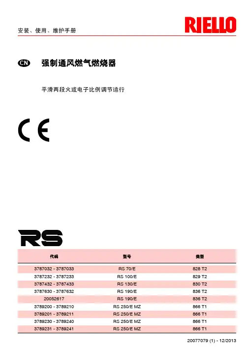
安装、使用以及维护说明书轻油燃烧器RL 190代码型号类型3475614 RL 190 673T1目录技术说明------------------------------------------------------------------------------------------------------2 技术参数----------------------------------------------------------------------------------------------------------------2 附件-----------------------------------------------------------------------------------------------------------------------------------------2 燃烧器描述----------------------------------------------------------------------------------------------------------------3包装-重量----------------------------------------------------------------------------------------------------------------3最大尺寸-----------------------------------------------------------------------------------------------------------------3标准配件-------------------------------------------------------------------------------------------------3燃烧出力------------------------------------------------------------------------------------------------------------------4测试锅炉------------------------------------------------------------------------------------------------------------------4安装----------------------------------------------------------------------------------------------------------4 锅炉法兰-----------------------------------------------------------------------------------------------------------------4燃烧头长度---------------------------------------------------------------------------------------------------------------4燃烧器与锅炉的连接-----------------------------------------------------------------------------------------------------4 1级,2级喷嘴的选择----------------------------------------------------------------------------------------------------5喷嘴的安装--------------------------------------------------------------------------------------------------------------5燃烧头的设定-------------------------------------------------------------------------------------------------------------5 油系统----------------------------------- -------------------------------------------------------------------6 燃料供给----------------------------------------------------------------------------------------------------------------6油路连接-----------------------------------------------------------------------------------------------------6接线图-----------------------------------------------------------------------------------------------------------------7泵的启动---------------------------------------------------------------------------------------------------------------9燃烧器调整--------------------------------------------------------------------------------------------------------------10燃烧器运行-------------------------------------------------------------------------------------------------11 最终检查-----------------------------------------------------------------------------------------------------------------12维护保养----------------------------------------------------------------------------------------------------------12燃烧器启动循环诊断-----------------------------------------------------------------------------------------------13 复位控制盒和使用诊断功能---------------------------------------------------------------------------------------13故障—可能原因—解决方法--------------------------------------------------------------------------------------14状态显示-----------------------------------------------------------------------------------------------------------------15本文中所提到的图形如下标识:1)(A)=图A的第1部分,与文本同页1)(A)p.4=图A的第1部分,页号4技 术 说 明型号 RL190 类别673T1 出力(1) 油耗(1) 大火KW Kcal/h Kg/h 1423-2443 1224-2100 120-206 小火 KW Kcal/h Kg/h 759-1423 653-1224 64-120 燃料 轻油 净热值 KWh/Kg Mcal/Kg 11.810.2(10,200) 比重 Kg/dm 3 0.82-0.8520℃时粘度mm 2/s 6( 1.5°E -6cSt ) 运行 间断(每24小时至少停1次 两段(高低火力)和单段(开-断)喷嘴 数目 2 标准应用锅炉:热水、蒸 汽、导热油炉环境温度 0C0-40助燃空气温度C 最大 60电源 V. Hz 230-400带中线±10%50Hz 三相 电机 rpm W V A 2800 4500220/240-380/41515.8 - 9.1 点火变压器 V 1-V 2 I 1-I 2 230V -2×5KV 1.9A -35mA 控制盒RMO88.53A2油泵输送能力(12 bar) 压力范围燃料温度Kg/h bar 0C 最大230 10-21 90电耗最大W 5870 电保护lP44 噪音水平(2)dBA 83.9 ECC 认可DIN 89/336 - 73/23 - 89/392 参考条件:1. 环境温度为20℃,压力为1bar ,海拔为100m 。

(感谢您选择本公司的产品,使用前请仔细阅读本说明书)回转窑多通道煤气两用燃烧器说明书郑州恒华建材机械配件有限责任公司目录一、概述.......................................................二型、系列煤煤气两用燃烧器的结构和工作原理--------------------三、现场安装要求---------------------------------------------------------- 四、点火及火焰的调整----------------------------------------------------五、维护和检俢------------------------------------------------------------ 六、常见故障及排除------------------------------------------------------七、对操作人员的要求---------------------------------------------------八、对煤粉系统的要求--------------------------------------------------九、特殊说明---------------------------------------------------------------概述水泥工业是耗能大户,其能耗主要包括:一是热耗约占80%,二是电耗约占20%,当前绝大部分的回转窑都是烧煤,目前我国许多水泥厂的煤耗占水泥成本的30%以上,因此成为当今水泥行业十分关注的,也是最重要的技术经济指标。
而节煤的根本途径就是采用先进的工艺技术装备。
在二十世纪七十年代以前,回转窑普遍使用单风道煤粉燃烧器,它的结构简单,但能耗高、环境污染大。
随着世界能源的日益紧张,国外一些水泥行业发达国家的著名公司在新型干法窑上率先使用双风道和三风道煤粉燃烧器。

正英燃烧器说明书
1、瓦斯热风装置安装可考虑以下两种方式
A、吸引方式
将循环热风吸入送入炉内之方式,循环风车在火焰之前方,通常称为使用负压。
B、押入方式
将循环热风吹出送入炉内之方式,循环风车在火炎之前方,通常称为使用正压。
2、一般在大容量时,母火燃烧器在主燃烧器点着火,以主燃烧器检查火炎然后熄灭母火燃烧器。
正英燃烧器DCM系列燃气燃烧器DCM30比例式燃烧器特点使用范围广泛,燃烧稳定。
3、简单的母火结构,点火稳定可靠。
主火可以使用高-低-停(Hi-Low-Off)功能,或PID比例调节。
采用简单确实且安全的检测方式。
空气扩散器使用坚固设计耐用不锈钢。
因为重量轻(与本公司之现有机种比较),故安装容易。
4、插入式结构,无需专门的燃烧室。
2902967 (0)安装, 使用及维护说明书强制通风燃气燃烧器编码型号类型3761900RS5920 T1一段火运行29671中文目录1.燃烧器描述一段火强制通风燃气燃烧器.1.1燃烧器附件带绝热垫的法兰. . . . . . . . . . . . . . 1 将法兰安装到锅炉上的螺栓和螺母. . . . . . . . . . . . . .. 4法兰用螺栓螺母 . . . . . . . . . . . . . 1 7针插头 . . . . . . . . . . . . . . . . . . . . . . . . . . . . . . . . . .1马达启动电容. . . . . . . . . . . . . . . 11.燃烧器描述. . . . . . . . . . . . . . . . . . . . . . . 11.1燃烧器附件. . . . . . . . . . . . . . . . . . . . . . . 12.技术参数. . . . . . . . . . . . . . . . . . . . . . . . . 22.1技术参数. . . . . . . . . . . . . . . . . . . . . . . . . 22.2外观尺寸. . . . . . . . . . . . . . . . . . . . . . . . . 22.3工作范围. . . . . . . . . . . . . . . . . . . . . . . . . 33.安装. . . . . . . . . . . . . . . . . . . . . . . . . . . . 43.1锅炉安装. . . . . . . . . . . . . . . . . . . . . . . . . 43.2燃气阀组电气连接. . . . . . . . . . . . . . . . . . 43.3燃气管线. . . . . . . . . . . . . . . . . . . . . . . . . 53.4电极定位. . . . . . . . . . . . . . . . . . . . . . . . . 53.5电气连接. . . . . . . . . . . . . . . . . . . . . . . . .64.工作 . . . . . . . . . . . . . . . . . . . . . . . . . . . .74.1燃烧调节 . . . . . . . . . . . . . . . . . . . . . . . . .74.2燃烧头设置 . . . . . . . . . . . . . . . . . . . . . . .74.3风门挡板设置. . . . . . . . . . . . . . . . . . . . . .84.4燃烧检查 . . . . . . . . . . . . . . . . . . . . . . . . .84.5燃烧器启动程序. . . . . . . . . . . . . . . . . . . .94.6空气压力开关. . . . . . . . . . . . . . . . . . . . . .95.维护 . . . . . . . . . . . . . . . . . . . . . . . . . . . .96.故障 / 解决方法 . . . . . . . . . . . . . . . . . . . .101–压力开关2–燃气阀组6 孔插座 3–带 7孔插座的控制盒4–带锁定指示灯的复位按钮 5–燃烧头安装座6–压力测试点7–带绝热垫的法兰8–风门调整机构 9–风门伺服马达燃烧器保护等级为IP 40, EN 60529.CE 认证: 参照燃气应用标准 92/42/EEC; PIN 0085BM0114.燃烧器符合下列标准:EMC 89/336/EEC, 低电压 73/23/EEC, 机械 98/37/EEC 和效率 92/42/EEC.燃气阀组符合 EN 676.图. 1SW100129672中文2.技术参数2.1技术参数对燃用LPG 可选特殊附件.2.2外观尺寸类型920 T1燃烧器出力 (1)160–330 kW-137,600–283,800 kcal/h天然气 (品种 2)净热值:8–12 kWh/Nm 3=7000–10,340 kcal/Nm 3压力:min. 20 mbar-max.100 mbar电源 单相,230V ± 10% ~ 50Hz马达运行电流 2A -2750 rpm-289 rad/s马达启动电容8 μF点火变压器初级 230V / 0.2A –次级8 kV / 12 mA电功耗0.43 kW(1) 参考条件: 温度. 20°C - 大气压力 1013 mbar – 海拔 0 m .国家ITGBDE AT DK FRNLBEIE燃气种类II2H3B/P II2H3PII2E3B/PII2H3B/PII2H3B/PII2Er3P II2L3B/P I2E(R)B,I3P II2H3P 燃气压力G20H 2020–2020–––20G25L ––––––2525–G20E––20––20/25–20/25–29673中文2.3工作范围 (参照 EN 267)实验锅炉以上工作曲线是用符合 EN 676 标准的锅炉测量得到.商用锅炉如果锅炉是符合 EN 303 标准,且燃烧室尺寸与 EN 676图表所示相近时,则燃烧器与锅炉是匹配的. 如果锅炉不是符合 EN 303 标准,且燃烧室尺寸比 EN 676图表所示更小 ,请咨询生产厂家.燃气压力与燃烧器出力的关系在用热值为10kWh/m 3(8.570 kcal/m 3)的G20燃气和锅炉背压在0 mbar 进行检测时,燃烧器最大出力时燃烧器头部的压降为 9.9 mbar(M2, 参见 3.3, P. 5).130,000290,000kW燃烧器出力kcal/h2.40.80燃烧室压力 – m b a rD62311.6170,000210,000250,0004.03.2kW燃烧器出力kcal/h632燃烧头的燃气压力 – m b a rD6232475891029674中文3.安装燃烧器的安装必须符合当地法规和标准.3.1锅炉安装♦如有必要, 对绝热垫扩孔(3) (参见图. 3).♦ 用4个螺钉 (4) 和螺母 (2) 将法兰(5)安装到炉门(1)上,必须将绝热垫 (3) 放在中间,但应保持上部两颗螺钉中的一颗松动 (4) (参见图. 2).♦用螺钉 6将法兰 5固定到燃烧头上 紧固,拧紧松动的螺钉 4.注意.: 燃烧器具有可调的燃烧头长度 (A) (参见图. 4).总之, 要保证燃烧头完全穿过锅炉前墙.3.2燃气阀组电气连接燃气阀组连接电线可从左边或右边进入燃烧器,如所示.根据进入燃烧器的方向, 带压力测试点的电缆孔堵简易电缆孔堵 (2) 可能需要互换因此, 必须确认:电缆孔堵 (1)位置正确;气管位置应正确,以保证空气通畅关造成阻塞.注意如有必要,可将气管切到正确的长度图. 2SW1003212D46051图. 529675中文3.3燃气管线符合 EN 676的燃气阀组燃气阀组单独供货, 它的调整参考附带的说明书.3.4探针 - 点火电极定位, (参见图. 7)燃气阀组连接方式应用型号编码入口出口MBDLE 410 B013970549Rp 11/4法兰 3天然气 ≤ 200kW 和 LPG 160 – 330 kWMBDLE 412 B013970550Rp 11/4法兰 3天然气 ≤ 300 kW MBDLE 415 B013970558Rp 11/2法兰 3天然气> 300 kWD52091 –供气管2 –手动球阀 (3 –燃气压力表 (4 –过滤器5 –燃气压力开关6 –安全阀7 –稳压器8 –调节阀M1–供气压力测试点M2–阀组后压力测试点29676中文3.5电气连接S7003230V ~50Hz(230V - 0.5 A max.)风门伺服马达图. 8; 断开连接器., 移开所有组件后, 7针 地线 (H) 拧松螺钉 (A,)紧上螺钉(A).29677中文4.工作燃烧出力燃烧器点火应在低负荷状态下进行并不超过120kW.为了测量燃烧出力:–断开离子探针电缆上的连接插头(C ) (参见电气连接P. 6); 燃烧器点火并在安全时间 (3s)过后锁定 .–进行10 次点火并连续锁定.–从流量表中读出耗气量. 该耗气量应等于或小于以下数值: G20 (天然气 H) 为0.10 Nm 3 G25 (天然气 L)为0.10 Nm 3 G31 (LPG)为0.03 Nm 3.4.1燃烧调整(参见图. 9)根据燃烧器应用于锅炉上的效率标准92/42/EEC ,调试燃烧器必须参考锅炉的使用说明书, 这一工作包括调整烟气中的 CO 和 CO 2 含量,烟温及锅炉中的平均水温.要达到所需要的出力, 要选择正确的燃烧头设定值和风门设定值.燃烧器出厂时设定在最小出力.4.2燃烧头设定根据燃烧器的出力,通过顺时针和逆时针旋转 设定螺丝 (6) 来进行,直到标尺 (2) 上的刻度值与燃烧头座 (1)的外边缘对齐.在图9中的燃烧头的设定是对应于燃烧器出力为230 kW.可见燃烧头的设定值为 4,即 标尺上的刻度值与燃烧头座的外边缘对齐 .示例:燃烧器安装在 210 kW 的锅炉.考虑到锅炉效率为 90%,燃烧器出力应为 230 kW.如图所示,燃烧头应设在 刻度4.注意此图表仅供参考;为了获得较好的燃烧效果,建议可根据锅炉调整燃烧头的设定.kcal/hkW设定点D6235SW1004图. 929678中文拆卸燃烧头组件, (参见图. 9, P. 7)按下列顺序操作:拧下螺钉(7), 断开连接插头 (3 和 5), 拆下小管 (4) 并拧松螺钉 (10)后拆下燃烧头座(1).在拆卸时不要改变燃烧头的肘型弯座 的设定.重新安装燃烧头组件, (参见图. 9, P.7)注意-在安装燃烧头时, 拧紧螺钉 (7) (不要拧太紧); 然后用力矩扳手( 3 - 4 Nm )锁紧.-如上操作确保燃烧器在运行时螺钉处不会有燃气泄露.- 如压力测点 (11) 松动,应正确固定并确保燃烧头组件(1)外部的孔 (F)安装在正确的位置上.4.3风门设定, (参见图. 9, P.7)在拧松螺母 (9)后对调节螺钉进行调整(8).燃烧器停机时风门会自动关闭,除非烟囱处最大压降大于0.5 mbar.4.4燃烧状况检查建议根据燃气种类和下表来初步设定燃烧器:离子探针电流燃烧器正常运行时控制器所需最小离子探针电流为 5 µA.一般情况下离子探针电流会远大于该值, 故不必检查. 如需要检查时, 可打开离子探针连接插头 (C) (参见页 6)串入微安电流表, (参见图. 10).在首次点火时风门设定不应小于1.EN 676过量空气系数:最大输出λ ≤ 1.2–最小输出λ ≤ 1.3燃气最大CO 2含量(0 % O 2)设定CO 2 %CO mg/kWhNO x mg/kWh λ = 1.2λ = 1.3G 2011.79.79.0 ≤100≤170G 2511.59.58.8 ≤100 ≤170G 3014.011.610.7 ≤100 ≤230G 3113.711.410.5≤100≤23029679中文4.5燃烧器启动程序由控制盒上的信号灯指示燃烧器锁定(4, 图. 1, P .1).在燃烧器运行时火焰消失, 燃烧器在1秒内停机.4.6空气压力开关空气压力开关的调整应在燃烧器的上述调整工作完成后进行,此时应设在初始位置.当燃烧器工作在额定出力时, 缓慢顺时针加大设定值,直至燃烧器锁定.然后逆时针旋转刻度盘将设定值减少20%, 并检查燃烧器是否能正常启动.如燃烧器锁定,应再少量减少空气压力开关的设定值.燃烧器出厂时空气压力开关在初始位置.注意:作为标准条例, 空气压力开关调整要防止当空气压力达到设定的 80% 时排烟中的 CO 超过 1% (10,000 ppm).如要检查这一点,请在烟囱中插入烟气分析仪, 缓慢关闭风机的进气口 (例如用纸板) 并检查在排烟中的CO 超过 1%之前是否会锁定.5.维护燃烧器必须由授权的和有资格的技术人员按照当地法规和标准进行定期性的维护.维护对于燃烧器运行的可靠性是必要的,可避免燃料的过量消耗以及随之而来的污染.在进行维护清理之前,必须将系统的主电源开关关掉,以切断燃烧器的电源.基本的检查有:让燃烧器不间断地运行10分钟,按本说明书检查所有组件的设置 . 然后进行燃烧测试以检查以下各项: CO 2 (%)的含量 排烟温度 CO (ppm)的含量.296710中文6.故障 / 可能的解决方法下表所示是造成启动故障或燃烧器非正常运行等问题的原因及相应的解决方法.故障通常会造成控制盒 (4, 图. 1, P. 1)复位按钮键中的锁定指示灯亮.当锁定灯亮时,只有按复位按钮燃烧器才会重新启动,此后如果燃烧器运行正常,锁定可以归因于偶然故障.如果继续锁定,一定要查找原因,并加以解决.燃烧器启动故障故障可能原因解决方法当启动温控器闭合时,燃烧器不启动.没有电源供应.检查7针插头中的L1-N 线之间的电压是否存在.检查保险丝的状况.检查安全温控器是否锁定 .没有燃气供应.检查手动球阀是否打开 .检查阀组是否打开并且是否有短路 .燃气压力开关不闭合.调整.控制盒中的连接错误.检查并连接插头.空气压力开关在运行位置.更换压力开关.风门挡板卡住.检查电气连接.风门没全关所以燃烧器不点火: 检查.在预吹扫及点火阶段时燃烧器运行正常,但3秒后锁定.火线与零线接反.重接.没有地线或接地不良.确保接地良好.离子探针接地,离子探针未与火焰接触,离子探针与控制盒连线断开,与地短路 .检查离子探针的位置,如有必要可按本说明书进行设置.重新电气连接.更换损坏的接线.燃烧器点火延迟点火电极位置不对.按本说明书所示进行调整.空气太多.按说明书所示进行调整.阀门开度太小,燃气量不够.调整.296711中文运行中故障燃烧器锁定: – 火焰消失– 探针接地– 空气压力开关断开燃烧器停机: – 燃气压力开关断开燃烧器在预吹扫后因火焰故障而锁定.电磁阀过气量较小.检查管网压力/按说明书所示调整电磁阀.电磁阀损坏.更换.点火脉动或失败.检查接头.按说明书所示检查电极的位置.管道空气没有排净.燃气管道放散.燃烧器在预吹扫时锁定.空气压力开关不切换.压力开关故障,更换.空气压力过低, (燃烧头调整不当).火焰出现.阀门故障: 更换.压力测试点 (11, 图. 9, p 7) 位置不对. 按说明书 p 7, 节 4.2调整好位置.燃烧器不锁定,重复启动.主燃气压力接近于最低燃气压力开关所限定的数值.阀门开启后燃气压力的突降,从而引起压力开关的暂时断开.阀门立刻关闭,燃烧器停机.压力又升高,压力开关再次闭合,重复点火周期,该过程没有休止地进行.减小最低燃气压力开关的设定值.故障可能原因解决方法。
第一章概述1、概述新型煤粉燃烧器是天津水泥工业设计院有限公司研制开发的新一代的燃烧设备,该项目课题组研究人员基于多年的实践经验,根据冷、热态实验的技术参数,以国内外的煤粉燃烧器为基础,采用现代最新燃烧技术的大速差和强旋流理论,结合全国原煤资源的特性以及我国水泥窑的燃料燃烧特点,运用计算机仿真技术,综合考虑多学科研究和发展成果研制而成。
该燃烧器适用于我国水泥生产行业各类回转窑,具有一次风量比例低、燃烧推力大的显著技术特点。
其高速的出口射流,大大强化了煤粉气流和二次热风的混合,最大限度消除了不完全燃烧,减少了不必要的热损失,并有利于降低热耗和利用低、劣质燃料;其独特的结构设计,具有灵便快捷的火焰调节手段,可使火焰形状随时满足窑内工况的需要,有利于建立合理的煅烧制度,提高产品质量;其卓越的燃烧特性,可提高回转窑的煅烧能力,充分发掘了设备的潜在能力以增加产量。
新型煤粉燃烧器由天津水泥工业设计院有限公司――中天仕名科技集团完成制造,本用户手册就用户关心的安装、操作及维护等问题作了较为详细的介绍,用户在使用设备之前必须仔细阅读。
2、燃烧器性能保证的前提条件用户需为本燃烧器的使用提供基本的使用条件,以保证TCNB-K32型回转窑用四风道煤粉燃烧器达到良好的使用效果。
本燃烧器性能保证的前提条件如下:●相关工艺系统正常;●窑头二次风温约1050℃左右;●送煤风配置误差最大不超过10% ;●送煤粉的空气中不得含有大颗粒的异物或棉纱等物;●燃烧器的喷嘴及煤粉入口处不允许出现堵塞现象。
第二章主要技术性能及参数1、基本概况:设备名称:TCNB新型煤粉燃烧器型号:5500t/d生产厂家:天津水泥工业设计研究院有限公司-中天仕名科技集团用途:用于5500t/d级 4.8x72m回转窑内的煤粉燃烧外形尺寸:12000(长度)X1200(高度)设备总重量:约20000kg(不包括风机)支撑小车型式:落地式配套回转窑产量:正常5000t/d水泥熟料最大5500t/d水泥熟料单位热耗:3094kJ/kg2、适应的煤粉成份及热值挥发分:29.15%灰分:19.43%水分:0.5% 最大2%低位热值:22990±1250 kJ/kg容重:0.84~0.89t/m3细度:0.08mm筛筛余8~10%温度:60~70℃3、输送煤粉用风机参数流量:62.4m3/min压力:49KPa温度:60~70℃4、燃烧器的性能及参数用煤量正常16000kg/h最大20000kg/h最小~1000kg/h送煤量调节范围: 1:6~1:10煅烧用主燃料: 煤粉点火用燃料:普通轻柴油燃烧器总长度: 约12000mm浇注料长度: 约6065mm燃烧器中心高:1750mm5、一次风机参数一次风机由买方自备,配置要求如下:轴流风机:1台形式:罗茨风机(带变频调速)风量:50~55m3/min风压:约96000 Pa旋流风机:1台(由旋流风道与外风道共用)使用厂家原有的一次风机形式:罗茨风机(带变频调速)使用风量:约90~95m3/min使用风压:约29400 Pa风机出口处需配有手动蝶阀和可曲挠合成橡胶接头6、点火用燃油液压系统参数燃料:普通轻柴油工作流量:4800 l/h工作压力: 5.5 MPa最高压力: 6 MPa系统流量:93 l/min贮油罐体积:8 m3齿轮泵:14MPa (25ml/r)滤油器精度:20μm该系统包括:具有进油和回油功能,带滤油器和压差显示器的泵阀控制站1台,带回流管的油枪1套,包括雾化器、软管、快速接头、截止阀,2个流量计用于固定在现场的管架上,第三章燃烧器部件清单一套完整的回转窑燃烧器设备,主要包括以下部件1、喷煤管本体(附图1)单重:~7000 kg数量:1套喷煤管本体中包括:●带蜗轮蜗杆调节装置的阀门3件,分别在生产中用于轴流风、旋流风及外风的调节;●带手柄式齿槽调节装置的阀门3件,分别在检修时用于冷却煤风管、油枪及轴流风管,这些阀门在生产中禁止使用。
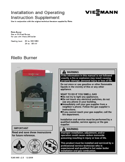
Installation and Operating Instruction SupplementUse in conjunction with the original technical literature supplied by Riello Riello BurnerGas or Oil-Fired Burnerfor use with Vitola200boilerHeating input83to300MBH24to88kWRiello BurnerIf theexactly,IMPORTANTRead and save these instructionsfor future reference.5265665v2.512/2009Safety,Installation and Warranty Requirements2Please ensure that this manual is read and understood before commencing installation.Failure to comply with the issues listed below and details printed in this manual can cause product/property damage ,severe personal injury ,and/or loss of life .Ensure all requirements below are understood and fulfilled (including detailed information found in manual subsections).Each of the following issues is very important and is discussed in detail in the boiler technical literature.Ensure that the installation complies fully and completely with all requirements set out in the boiler technical literature.H Licensed professional heating contractorThe installation,adjustment,service,and maintenance of this equipment must be performed by a licensed professional heating contractor."Please see section entitled “Important Regulatory and InstallationRequirements”.H Product documentationRead all applicable documentation before commencing installation.Store documentation near boiler in a readily accessible location for reference in the future by service personnel."For a listing of applicable literature,please see section entitled “Important Regulatory andInstallation Requirements”.H Advice to ownerOnce the installation work iscomplete,the heating contractor must familiarize the systemoperator/ultimate owner with all equipment,as well as safetyprecautions/requirements,shut-down procedure,and the need forprofessional service annually before the heating season begins.H Contaminated airAir contaminated by chemicals can cause by-products in the combustion process which are poisonous to inhabitants and destructive to Viessmann equipment.H Carbon monoxideImproper installation,adjustment,service and/or maintenance can cause flue products to flow into living space.Flue products contain poisonous carbon monoxide gas.H Fresh airThis equipment requires fresh air for safe operation and must be installed ensuring provisions for adequate combustion and ventilation air exist.H Equipment ventingNever operate boiler without an installed venting system .H WarrantyInformation contained in this and related product documentation must be read and followed.Failure to do so renders warranty null and void.5265665v 2.5Do not chlorine near the Never adequate air.AllContents3PageSafety Important Regulatory and Installation Requirements4....Set-upProduct Delivery 4.......................................................................Mounting Burner5......................................................................Burner Set-up -Gas 6.................................................................Burner Set-up -Oil10...................................................................Oil Cartridge Assembly 13...........................................................Burner Set-up -Gas and Oil13..................................................Start-up/AppendixStart-up Information 14................................................................Technical Data 15..........................................................................Wiring Diagram18.........................................................................Maintenance Record20...............................................................OperationLighting Instructions23...............................................................5265665v 2.5Safety4Take note of all symbols and notations intended to draw attention to potential hazards or important productinformation.Set-up5Installation1.Remove burner from carton.The universal mounting flange has been installed on the burner at the factory.2.Mount burner as shown in Figs.1and 2.5265665v 2.5Fig.1Installing burnerFig.2Securing burner flange to combustion chamberdoorSet-up6InstallationThe gas train may be mounted on the left or on the right side of burner.G200burners have a ½”NPT female gas connection.G400burners have a ¾”NPT female gas connection.Gas trainNG flow pressure:min. 4.0”w.c.max.10.5”w.c.LP flow pressure:min.8.0”w.c.max.13.0“w.c.Legend (Fig.3)Gas supply and gas flow direction Gas shut-off valve (field supplied)Gas supply pressure test point (field supplied)Gas train pipe diameter(s)Burner G200½”NPT Burner G400¾”NPTMaxitrol RV52with RV5210-13(brown spring 1.0to 3.5”w.c.)gas appliance pressure regulator Honeywell gas solenoid valve V8295N.C.(24V operated)Dungs MVD-LE model 200G200=MVD-LE 205/6(24V)G400=MVD-LE 207/6(24V)Gas burner manifold test pointGas piping pressure testThe burner and its gas connection must be leak-tested before placing theboiler/burner combination in operation.The burner and its individual shut-off valve must be disconnected from the gas supply piping system during any pressure testing of that system atpressures in excess of 0.5psig/3.5kPa.Unions and manifold have been factory-tested.Leak test must be repeated during initial operation of burner by heating contractor.Never check for gas leaks with an open e approved spray liquid or soap water solution for bubble test.5265665v 2.5IMPORTANTFig.3Gas train Field Supplied Viessmann Supplied"Set-up7Flow adjustment cap Pan head screwSealing cap/adjustment cap toolBurner manifold gas pressure adjustmentThe burner manifold gas pressuresettings must be performed using the RV52gas appliance regulator only .In the event of low gas supply pressure,increase gas supply pressure using the RV52gas regulator to required minimum gas supply pressure.Operating and Installation Instructions for gas train components (supplied)No preliminary adjustments required for Honeywell V8295N.C.gas solenoid valve.Adjustment steps1.Attach manometer to burner manifoldtest point (combustion head ).2.Start up burner and observe.3.Wait until burner has stabilized to adjust burner manifold pressure using the RV52gas appliance regulator,and set to required burner manifold pressure setting.Use factory default settings (pages 15and 16)as starting point only.4.To adjust the initial lift gas pressure remove sealing cap,exposing the lift adjustment knob,turn over cap,adjust knob to “+”to increase the start pressure and set to approx.0.7to 0.9“w.c.(manifold pressure).Factory default setting is set to 100%full flow.5.Restart appliance at least three times to finalize gas manifold setting and to determine a smooth ignition.6.If burner fails to ignite or ignition is delayed or hard,one or more of the following corrective actions may be required:H Adjust initial gas pressure settingon Dungs gas valve.H Ignition electrode and/or ionization (flame)rod is not set withinspecified range,adjust setting by referring to original Installation Instructions of Riello burner.5265665v 2.5Fig.4MVD-LE valve,sideviewFig.5MVD-LE valve,top viewIMPORTANTIMPORTANTIMPORTANTSet-up8Verifying input of gas boilersNatural gas burners must have gas input clocked using the gas meter.Ensure there is no gas flowing through the meter other than to the gas-fired boiler being checked.See pages 15and 16for gas flow rate and values for time (in seconds)for clocking gas meter.Clock at least 10revolutions on a one ft 3gas meter dial and divide time by 10.The value arrived at should be the same as shown on pages 15and 16.If necessary,manifold pressure must be adjusted to make sure burner is firing at nominal input.Do not exceed gas input stated on rating plate.Turn adjustment screw on gas pressure regulator (RV52)clockwise to increase gas flow,and counterclockwise to decrease gas flow (as per instructions on the previous page).If checking gas input with a manometer only use manifold pressures given in manual as a starting point,and use combustion instruments to ensure safe and efficient combustion values.Be sure to turn gas off before attaching or removing pressure taps.All plugs removed for the purpose of gas pressure measurements must be replaced and leak-tested after Replacement of 24V gas valveUse only replacement gas valves from Viessmann Manufacturing.The 24VAC Dungs ¾”MVD-LE 207/6and ½”MVD-LE 205/6direct spark valves are special valves designed to operate at the low manifold pressures required by the Riello burner for both natural and propane gas.Do not use other gas valve unless specified by Viessmann.Field measured combustion resultsUse the combustion data label packed with the gas burner to record fieldmeasured combustion results and affix label to gas burner.Adjustment data tag ANSI Z21-17b-1994Input:C.F.H.Manifold pressure Air damper Air/gas ratio No.Flue gas temp.O 2level:%CO 2level:ppm DateCompleted by Installing contractorIt is necessary to follow all safety information in the Riello technical literature as well as all other OEM component instructions shipped with this manual.The Viessmann factory settings are an initial guide to be verified or changed by the installer based on field measured combustion results.The burner settings arrived at during field measurements may be different from the generalizedconversion burner settings given in the Riello technical literature.5265665v 2.5IMPORTANTEach Riello manifold gas valve,IMPORTANTSet-up9Summary of changes to original Rielloburner Note the following constructiondifferences between the general Riello conversion burner and Riello burnersupplied for use on the Vitola boiler.N200and P200burners for use with Vitola 200VB2-18to VB2-40The 40-(N,P)200gas burners when supplied by Viessmann for VB2-18and -22are constructedwith drawer assembly diaphragm installed in the combustion head assembly for natural gas andpropane.SleeveDrawer assembly diaphragm OrificeThe main gas orifice for natural gas is changed from the 2.0mm orificenormally supplied with a 40-(N,P)200aftermarket conversion burner to that stated in the table below.The differences in orifice size for the VB2-18,-22cause the manifoldpressure adjustment information in the Riello 40-(N,P)200manual to be not e the manifold pressures in this manual as a starting point for burner adjustment for the VB2-18,-22.Do not change orifice,diaphragm or sleeve-combination.Contact the Viessmann Technical Department.Burner Model Model No.Boiler G200VB2-18G200VB2-22G200VB2-33G200VB2-40OrificeLP1.3 1.3 1.3 1.3SleeveNG n.a.installed installed n.a.LPinstalled installed installedinstalledDiaphragmNG installed installed n.a.n.a.LPinstalledinstalledn.a.n.a.n.a.=not applicable5265665v 2.5IMPORTANTH:15.8mm W:19.5mmN88mm 19m mSet-up10The oil burner is provided with its own oil filter and built-in flow check valve.The flow check valve is located in the return,and a manual shut-off is located in the supply.One-pipe systems1.Connect as shown in Fig.6.5265665v 2.5Fig.6Connection to a one-pipesystemSet-up112.Mount filter support bracket either on the side of the boiler (Fig.7)or on the front of the boiler (Fig.8).3.Mount filter and check valve assembly to mounting bracket (Fig.9).Filter is disposable type and must be replaced with the filter cartridge supplied by Viessmann.5265665v 2.5Fig.7Side-mounting support bracketFig.8Front-mounting supportbracketFig.9Mounting filter and check valveassemblySet-up12oil line from tankto oil pump on burner from oil pump on burner recirculation to filter4.Connect flexible oil lines to the filter check valve assembly.See Fig.10.Red:supply (connection with the red manual valve)Blue:return (connection with the check valve).The Riello burner shipped by Viessmann comes with the bypass plug alreadyinstalled,ready for two-pipe connection.For a one-pipe system (gravity system where the oil tank is above the burner)use the copper tee provided.This tee converts the two-pipe system to a one-pipe system.The oil not used by the pump recirculates into the supply line.Pipe sealant must be used on the threaded ends of the flare fittings which join the copper tee to the filter check valve assembly .5.Install tee as shown in Fig.11.5265665v 2.5Fig.10Connect oil supply and returnlinesFig.11Converting two-pipe system to one-pipe systemSet-up131.Check that all surfaces are clean before installing new O-ring supplied with replacement filter cartridge.2.Set O-ring in place and mount new filter cartridge.3.Attach clear plastic cup and tighten brass nut.Never tighten brass nut with a tool;hand tighten only.Cap and O-ring mightdeform and leak air.The flare adaptors are tapped 3/8”BSP (British straight pipe)at the factory.Replacement flare adaptors must be ordered from Viessmann.Do not use 3/8”NPT flare adaptor as replacement.Burner Set-up -Gas and OilRefer to Riello instructions for adequatefuel supply pipe sizing and sequence of burner operation.Ensure an adequate supply of fresh combustion and ventilation air for safe operation.Refer to codes mentioned on page 4.Electrical connections1.Run the plug-in connector cable of the Vitotronic control down behind the front panel of the boiler and out through the wire strain relief as per the boiler installation instructions (Electrical Connections).2.Connect the female plug of the burner to the male plug of the Vitotronic control.See Fig.13.Installation Instructions Riello gas or oil burner5265665v 2.5Fig.12Oil cartridge assemblyIMPORTANTIMPORTANTWhen mounted,cup.Check IMPORTANTFig.13The quick-connect plug-insystemStart-up Information14Boiler start-upStart-up/Service Instructionsof boiler,as well as literature of burner,burner test sheet and control literature.Combustion analysisThis gas or oil burner requires combustion measurements to beperformed at the final installation site by a licensed heating contractor toverify factory settings,or to be used as a guide in changing burner settings to suit local conditions.Examples of local conditions which influence combustion results include:weather conditions,length of horizontal vent pipe,diameter and height of the chimney,side wall venting (power vent),altitude above sea level,quality and heating value of gas or oil used,maximum number of other fuel burning appliances running at the same time.These conditions affect the burnerset-up.The burner must be adjusted for acceptable combustion results under local conditions of the installation.When the boiler is fired for the first time,the ceramic fiber insulation at the back of the combustion chamber door will require ½to 1hour of firing time to “cure”.An odor may occur during this time.Final measurements of CO must be done only after the “cure”is complete.Combustion measurements (CO 2,stack temperature,draft and CO)are taken in the flue pipe between boiler and barometric draft regulator beforedilution air (see the installation manual).Overfire draft is measured at thecombustion chamber observation port opening.The expected CO 2products of combustion are printed below.These values are based on average results -slightly higher or lower values may be suitable depending on installation conditions.Fuel NG LP Oil CO 29.5to 10.2%10.0to 11.5%11.0to 13.0%The CO concentration should be asshown on the Viessmann quality control burner test results.If the COconcentration is above 50ppm,then measures should be taken to decrease concentration to a value below 50ppm.Steps to be taken include:ensuring sufficient supply of combustion air,adjusting air gate settings,ensuring chimney and vent are correct and meet safety codes,verifying boiler input and burner settings,replacing any defective part on burner,contactingmanufacturer’s technical sales representative for assistance.5265665v 2.5IMPORTANTTest port for combustion analysis equipmentDO NOT CRANKCASE OIL CONTAINING Do not controls.DO NOT BURNER ACCUMULATED,Appendix15Natural gasThe above specifications are for 0-2000ft.above sea level.Burner test resultsThe indicated values for manifold and air gate settings are the result of production line testing under ideal conditions.Final burner adjustment to suit local field conditions is necessary for safe operation.Observe the stated minimum and maximum supply gas pressures.Exposing the burner gas train to supply pressures other than the stated values can cause unsafe conditions.Viessmann strongly recommends the installation of an approved type CO detector in the vicinity of any gas burning equipment.Observe national and/or local code requirements.If in doubt consult your local gas company.Verification of resultsThe burner adjustment values indicated serve as a starting point bustion results must be field verified using properly calibratedBacharach or equivalent instruments.Each burner is certified for one input only.Do not overfire or underfire burner.Technical dataFuel natural gas ...........................................Averageheating value 1000MBH/ft 3...................Inlet gas pressuremin.4.0”w.c............max.10.5”w.c.Draft regulatorVB2-18to -40MG16”...........................VB2-50to -63MG17”...........................Overfire draft +0.01”w.c......................Max.breeching draft -0.02”w.c...........INPUT =3600/T x 1000where T =TIME (sec.)for 1ft 3natural gas INPUT =(3600x 0.01x 1000x 35.31)/T where T =TIME (sec.)for 0.01m 3natural gas5265665v 2.5Do not Factory changed IMPORTANTAppendix16Liquid propaneThe above specifications are for 0-2000ft.above sea level.Burner test resultsThe indicated values for manifold and air gate settings are the result of production line testing under ideal conditions.Final burner adjustment to suit local field conditions is necessary for safe operation.Observe the stated minimum and maximum supply gas pressures.Exposing the burner gas train to supply pressures other than the stated values can cause unsafe conditions.Viessmann strongly recommends the installation of an approved type CO detector in the vicinity of any gas burning equipment.Observe national and/or local code requirements.If in doubt consult your local LP company.Verification of resultsThe burner adjustment values indicated serve as a starting point bustion results must be field verified using properly calibratedBacharach or equivalent instruments.Each burner is certified for one input only.Do not overfire or underfire burner.Technical dataFuel propane gas .........................................Averageheating value 2500MBH/ft 3...................Inlet gas pressuremin.8”w.c............max.13”w.c.Draft regulatorVB2-18to -40MG16”...............VB2-50to -63MG17”...............Overfire draft +0.01”w.c....................Max.breeching draft -0.02”w.c......INPUT =3600/T x 2500where T =TIME (sec.)for 1ft 3propane gas INPUT =(3600x 0.01x 2500x 35.31)/T where T =TIME (sec.)for 0.01m 3propane gas5265665v 2.5Do not Factory changed IMPORTANTAppendixFig.14Air tube insertion (VB2-18,-22,-33)a asemi-flange(VB2-40,-50,-63)17Fuel oil No.2In multiple-boiler installations,a booster pump may be required.F10burners for use with Vitola 200VB2-50,VB2-63The F10as supplied by Viessmann uses the 10”long tube and a specialturbulator disc and end cone unique to Viessmann.Order replacements from Viessmann only.5265665v 2.5IMPORTANTAppendix18Vitotronic boiler controlRiello burner120VAC,60Hz,2.5ABurner plug-in connector(male and female)Primary control connections;connect blue wire to the followingterminal on the control box:Fuel NG LP OilTerminal776Motorized air damper(gas burneronly)Low water cut-off(field supplied,if required)Heating system ON/OFF switch120VAC,installer must provide15A overcurrent protectionReceptacle(site)120VACInstall the boiler as described in itstechnical documentation beforeinstalling or operating the burner.120VAC is supplied to burner viaplug-in connector.Do not connectadditional120VAC to burner.If any of the original wires as suppliedwith the appliance must be replaced,replace with221°F/105°C rated or itsequivalent.Minimum size18AWG.5265665v2.5LWCOTurn offsupplyContactLabelwhencan causeAppendix191.Install blocked vent switch(see enclosed FieldControls WMO-1Installation Instructions).2.Run BX cable (armored cable)or any other approved wire (required by local authorities having jurisdiction)from WMO-1switch to burner e nominal ½”electrical knockout provided on Riello plate forconnectors.If necessary,relocate wiring harness strain relief to other electrical opening provided.3.Disconnect black wire (BK)of 7-poleplug from oil burner primary control base.4.Rewire (wire nut included)the black wire (BK)through WMO-1safety switch and back to terminal “L”of the oil burner primary control.52Legend BK Black BU Blue GN Green RD Red WHWhiteFor use Do not sidewallAppendix20Service binder1.File all Parts Lists,Operating and Service Instructions in the Service Binder.2.Install a protective hanging case near the boiler and store the Service Binder in this location.MaintenanceBefore each heating season begins,have the following service and maintenance done by a licensed,professional heating contractor:1.Boiler heat exchanger inspected and cleaned.2.Vent system inspected fordeterioration,leaks,corrosion,proper draft,and proper operation.Check vent system for compliance withlocal and national code requirements.Repair or replace as required.3.Burner checked and,if necessary,adjusted for proper combustion and operation.Check for adequate supply of fresh outside combustion and ventilation air.5265665v 2.5Neglecting maintenance operation.Appendix215265665v 2.5Appendix225 2 6 5 6 6 5 v 2 . 5OperationManual gas shutoffOpenClosedTO1.Set thermostat or other operating controlsetting.2.Turn off all electric power to the applianceis to be performed.3.Close main gas shut-off valve.23Viessmann Manufacturing Company Inc.750McMurray RoadWaterloo,Ontario •N2V 2G5•CanadaTel.(519)885-6300•Fax (519)885-0887www.viessmann.ca •*****************Viessmann Manufacturing Company (U.S.)Inc.45Access RoadWarwick,Rhode Island •02886•USATel.(401)732-0667•Fax (401)732-0590 •*********************24Conversion Table H “w.c.x 2.54=mbar H mbar x 0.394=“w.c.H kW x 3413=Btu H bar x 14.5=psigH kg x 0.289=USG (#2oil)H BHP x 9.8=kW H BHP x 33779=Btu H m x 3.28=ft.H m 3x 35.3=ft.3H kcal x 3968=BtuH Cal value NG =950-1050Btu/ft.3H Cal value LP =2450-2500Btu/ft.3H Motor kW x 1.31=Motor HPNG Natural Gas LP Liquid PropaneQuick Reference °C °F -40-40-35-31-25-13-20-4-180-16+3-14+7-12+10-10+14-9+16-8+18-7+19-6+21-5+23-4+25-3+27-2+28-1+300+32+1+34+2+36+3+37+4+39+5+41+6+43+7+45+8+46+9+48+10+50+12+54+14+57+16+61+18+64+20+68+25+77+30+86+35+95+40+104+50+122+60+140+70+158+80+176+90+194+100+212+110+2305265665v 2.5T e c h n i c a l i n f o r m a t i o n s u b j e c t t o c h a n g e w i t h o u t n o t i c e .。
FRQ-2DF双燃料燃烧器说明书福尼燃烧控制研究院二○一○年十月前言_____________________________________________________________________注意感您使用福尼燃烧控制研究院生产的FRQ-2DF型燃烧器。
本手册作为产品完整而必要的一部分提供给用户。
本手册所述容不仅适用于用户,也可为产品的安装和检修人员提供参考。
关于设备的安装、操作和维护的详细信息,我们建议您仔细阅读。
请妥善保存本手册,以备参考。
_____________________________________________________________________容介绍:本手册介绍了FRQ-2DF型双燃料燃烧器的结构、特点、安装、操作、维护以及故障处理。
读者对象:本手册适合下列人员阅读:设备安装人员、操作人员、维护人员等。
一、用途及特点FRQ-2DF型系列双燃料燃烧器是福尼燃烧控制研究院设计开发的节能燃烧设备,它可在工业锅炉、电站锅炉及其它工业窑炉中广泛应用。
FRQ-2DF型双燃料燃烧器能实现助燃风与燃料按比例调节,使燃烧更为稳定可靠,实现全自动运行。
它具有结构紧凑、燃烧稳定、调节比大、噪音低、可设点火枪和火焰检测报警系统;火焰铺展性好、燃烧完全、燃烧易于控制等特点。
二、主要性能及技术参数1.燃烧器功率:18.5MW/台2.燃烧器调节比:5:13.燃料油参数:油压(枪前油压):1.0~1.2Mpa油枪出力:每台燃烧器1450kg/h雾化式:蒸汽雾化4.雾化吹扫蒸汽:雾化蒸汽设计流量:300Kg/h雾化蒸汽设计压力(燃烧器前表压):1.0MPa5.燃料气(干气):燃气流量:每台燃烧器2000 Nm3/h燃气气压力(进阀组前):25Kpa燃气温度:常温6.助燃风助燃风温度:常温助燃风压:3500~4500Pa助燃风量:~20000Nm3/h7.点火燃气;点火燃气:干气点火燃气压力:10KPa点火燃气流量:100Nm3/h三、燃烧器及主要配置介绍1.燃烧器燃烧器为双燃料型燃烧器,主要由燃烧器本体、配风器、稳焰装置、燃油喷枪、燃油火检、燃气火检、主气嘴、点火长明灯等组成。