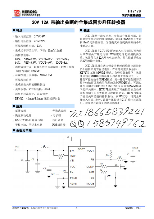
SIC414:microBUCK同步降压稳压器
- 格式:pdf
- 大小:81.40 KB
- 文档页数:1

TL431的工作原理TL431是一种精密可调电压参考电源,常用于电源管理、电压稳定和电流控制等应用中。
它是一种三端稳压器,由美国德州仪器(Texas Instruments)公司设计和生产。
TL431的工作原理基于反馈控制的概念。
它的输入端(Anode)连接到待调节的电压,输出端(Cathode)连接到负载,而参考端(Reference)连接到一个参考电压源(通常是一个稳压二极管或电阻分压电路)。
通过调节参考端的电压,TL431可以实现对输出电压的精确控制。
TL431内部有一个比较器和一个可调电流源。
比较器将参考电压与反馈电压进行比较,产生一个误差信号。
可调电流源根据误差信号的大小,调整输出电流,从而实现对输出电压的调节。
当参考电压大于反馈电压时,比较器输出低电平,可调电流源关闭或输出较小的电流,从而使输出电压上升。
当参考电压小于反馈电压时,比较器输出高电平,可调电流源打开或输出较大的电流,从而使输出电压下降。
通过不断调整参考电压和输出电流,TL431能够稳定输出所需的电压。
TL431还具有过温保护功能。
当芯片温度超过一定阈值时,内部的过温保护电路将启动,将输出电压降低至安全范围,保护芯片免受损坏。
TL431的特点包括高精度、低温漂移、低噪声、高稳定性和快速响应等。
它的工作电压范围通常为2.5V至36V,最大输出电流可达100mA。
由于其性能可靠,TL431被广泛应用于电源管理、电压稳定、电流控制、电池充电管理等领域。
总之,TL431是一种精密可调电压参考电源,通过反馈控制实现对输出电压的精确调节。
它具有高精度、低温漂移、低噪声和高稳定性等特点,适用于各种电源管理和电压稳定的应用。

1Rev. 0DESCRIPTIONLT8618CHigh Efficiency 65V, 100mA Synchronous Buck RegulatorDemonstration circuit 3214A features the LT ®8618C , a high efficiency 65V, 100mA synchronous step-down reg-ulator in 12-Lead 2mm × 2mm LQFN package. The demo board is designed for 100mA at 5V output from a 5.9V to 65V input, with the switching frequency programmed at 2MHz.The LT8618C is a compact high efficiency, and high fre-quency synchronous monolithic step-down switching regulator , with internal soft-start capacitor , compensation network, BST and INTV CC capacitors.The operation mode can be configured via the SYNC/MODE pin for forced continuous mode, Burst Mode ® operation, or spread spectrum mode. The low quiescent current and high efficiency in Burst Mode make it an ideal solution for applications requiring highest efficiency atAll registered trademarks and trademarks are the property of their respective owners.PERFORMANCE SUMMARYlight load conditions, such as automotive housekeep-ing supplies, industrial sensors, flow meters, Internet of Things, and battery powered portable instruments.The demo board DC3214A has an EMI filter installed. The EMI performance of the board running in spread spec-trum mode is shown in Figure 2, where the red lines are CISPR25 Class 5 average limits. The circuit passes the average limit with a wide margin.The LT8618/LT8618C data sheet gives a complete description of the part, operation, and application infor-mation. The data sheet must be read in conjunction with this demo manual. Contact ADI applications engineer for technical support.Design files for this circuit board are available .Specifications are at T A = 25°CSYMBOL PARAMETER CONDITIONSMIN TYP MAX UNITSV IN Input Supply Range 5.965V V OUT Output Voltage4.8555.15V I OUT Maximum Output Current 100mA f SW Switching Frequency, FCM V IN = 12V , I OUT = 100mA 1.852 2.15MHz EFFEfficiency, FCMV IN = 12V , I OUT = 100mA89%2Rev. 0QUICK START PROCEDUREDC3214A is easy to set up to evaluate the performance of the LT8618C. Refer to Figure 1 for proper measurement equipment setup and follow the procedure below:1. With power off, connect the DC power supply to VEMI or VIN and GND, and load from VOUT to GND.2. By default, JP1 is connected to VOUT, and JP2 to FCM.3. Turn on the power at the input. Check for the proper output voltage (5V).4. Once the proper output voltage is established, adjust the line/load within the operating ranges and observe the output voltage regulation, ripple voltage, load transient, efficiency, and other parameters.Figure 1. Proper Measurement Equipment Setup3Rev. 0QUICK START PROCEDUREFigure 2. Conducted and Radiated EMI performance of the DC3214A. V IN = 14V, I OUT = 100mA, Spread Spectrum ModeCISPR25 Radiated EMI PerformanceCISPR25 Conducted Emission PerformanceVoltage MethodPARTS LISTITEM QTY REFERENCE PART DESCRIPTION MANUFACTURER/PART NUMBERRequired Circuit Components11C1CAP., 22µF, ALUM. ELECT., 63V, 20%, 6.3x7.7mm, CE-BS SUN ELECTRONIC INDUSTRIES CORP, 63CE22BS 23C2, C3, C10CAP., 1µF, X7S, 100V, 20%, 0805MURATA, GRJ21BC72A105ME11L31C8CAP., 0.01µF, X7R, 16V, 10%, 0603AVX, 0603YC103KAT2A41C9CAP., 4.7µF, X5R, 6.3V, 10%, 0603KEMET, C0603C475K9PACTU51C12CAP., 0.1µF, X7R, 100V, 10%, 0603AVX, 06031C104KAT2A61C15CAP., 22µF, X5R, 16V, 10%, 1206AVX, 1206YD226KAT2A71FB1IND., 300Ω, FERRITE BEAD, 25%, 250mA, 0402, AEC-Q200MMZ1005Y301CTD2581L1IND., 47µH, PWR, SHIELDED, 30%, 0.39A, 940mΩ, 3816WURTH ELEKTRONIK, 74403147092R1, R4RES., 1M, 1%, 1/10W, 0603, AEC-Q200VISHAY, CRCW06031M00FKEA101R2RES., 18.2k, 1%, 1/10W, 0603, AEC-Q200PANASONIC, ERJ3EKF1822111R3RES., 49.9k, 1%, 1/10W, 0603NIC, NRC06F4992TRF121R5RES., 187k, 1%, 1/10W, 0603, AEC-Q200PANASONIC, ERJ3EKF1873V131U1HIGH EFFICIENCY 60V/100mA, LQFN-12ANALOG DEVICES, LT8618CAV#TRMPBF Additional Demo Board Circuit Components10C5, C14CAP., 10pF, C0G, 16V, 5%, 0603, OPT20C6CAP., 10µF, X5R, 6.3V, 20%, 0603, OPT50R6, R7RES., OPTION, 0603Hardware: For Demo Board Only112E1-E12TEST POINT, TURRET, 0.094" MTG. HOLE, PCB 0.062" THK MILL-MAX, 2501-2-00-80-00-00-07-0 21JP1CONN., HDR, MALE, 1x3, 2mm, VERT, ST, THT, NO SUBS.WURTH ELEKTRONIK, 62000311121ALLOWED31JP2CONN., HDR, MALE, 2x4, 2mm, VERT, ST, THT WURTH ELEKTRONIK, 6200082112141XJP1, XJP2CONN., SHUNT, FEMALE, 2 POS, 2mm WURTH ELEKTRONIK, 6080021342154MP1-MP4STANDOFF, NYLON, SNAP-ON, 0.50"WURTH ELEKTRONIK, 7029350004Rev. 05Rev. 0Information furnished by Analog Devices is believed to be accurate and reliable. However , no responsibility is assumed by Analog Devices for its use, nor for any infringements of patents or other rights of third parties that may result from its use. Specifications subject to change without notice. No license is granted by implication or otherwise under any patent or patent rights of Analog Devices.SCHEMATIC DIAGRAMA N A L O G D E V I C E S H A S M A D E AB E S T E F F O R T T O D E S I G N AC I R C U I T T H A T M E E T S C U S T O M E R -S U P P L I ED S PE C IF I C A T I O N S ;H O W E V E R , I T R E M A I N S T H E C U S T O M E R 'S R E S P O N S I B I L I T Y T O6Rev. 0ANALOG DEVICES, INC. 202111/21ESD CautionESD (electrostatic discharge) sensitive device. Charged devices and circuit boards can discharge without detection. Although this product features patented or proprietary protection circuitry, damage may occur on devices subjected to high energy ESD. Therefore, proper ESD precautions should be taken to avoid performance degradation or loss of functionality.Legal Terms and ConditionsBy using the evaluation board discussed herein (together with any tools, components documentation or support materials, the “Evaluation Board”), you are agreeing to be bound by the terms and conditions set forth below (“Agreement”) unless you have purchased the Evaluation Board, in which case the Analog Devices Standard Terms and Conditions of Sale shall govern. Do not use the Evaluation Board until you have read and agreed to the Agreement. Your use of the Evaluation Board shall signify your acceptance of the Agreement. This Agreement is made by and between you (“Customer”) and Analog Devices, Inc. (“ADI”), with its principal place of business at One Technology Way, Norwood, MA 02062, USA. Subject to the terms and conditions of the Agreement, ADI hereby grants to Customer a free, limited, personal, temporary, non-exclusive, non-sublicensable, non-transferable license to use the Evaluation Board FOR EVALUATION PURPOSES ONL Y. Customer understands and agrees that the Evaluation Board is provided for the sole and exclusive purpose referenced above, and agrees not to use the Evaluation Board for any other purpose. Furthermore, the license granted is expressly made subject to the following additional limitations: Customer shall not (i) rent, lease, display, sell, transfer , assign, sublicense, or distribute the Evaluation Board; and (ii) permit any Third Party to access the Evaluation Board. As used herein, the term “Third Party” includes any entity other than ADI, Customer , their employees, affiliates and in-house consultants. The Evaluation Board is NOT sold to Customer; all rights not expressly granted herein, including ownership of the Evaluation Board, are reserved by ADI. CONFIDENTIALITY. This Agreement and the Evaluation Board shall all be considered the confidential and proprietary information of ADI. Customer may not disclose or transfer any portion of the Evaluation Board to any other party for any reason. Upon discontinuation of use of the Evaluation Board or termination of this Agreement, Customer agrees to promptly return the Evaluation Board to ADI. ADDITIONAL RESTRICTIONS. Customer may not disassemble, decompile or reverse engineer chips on the Evaluation Board. Customer shall inform ADI of any occurred damages or any modifications or alterations it makes to the Evaluation Board, including but not limited to soldering or any other activity that affects the material content of the Evaluation Board. Modifications to the Evaluation Board must comply with applicable law, including but not limited to the RoHS Directive. TERMINATION. ADI may terminate this Agreement at any time upon giving written notice to Customer . Customer agrees to return to ADI the Evaluation Board at that time. LIMITATION OF LIABILITY. THE EVALUATION BOARD PROVIDED HEREUNDER IS PROVIDED “AS IS” AND ADI MAKES NO WARRANTIES OR REPRESENTATIONS OF ANY KIND WITH RESPECT TO IT . ADI SPECIFICALL Y DISCLAIMS ANY REPRESENTATIONS, ENDORSEMENTS, GUARANTEES, OR WARRANTIES, EXPRESS OR IMPLIED, RELATED TO THE EVALUATION BOARD INCLUDING, BUT NOT LIMITED TO, THE IMPLIED WARRANTY OF MERCHANTABILITY, TITLE, FITNESS FOR A PARTICULAR PURPOSE OR NONINFRINGEMENT OF INTELLECTUAL PROPERTY RIGHTS. IN NO EVENT WILL ADI AND ITS LICENSORS BE LIABLE FOR ANY INCIDENTAL, SPECIAL, INDIRECT , OR CONSEQUENTIAL DAMAGES RESUL TING FROM CUSTOMER’S POSSESSION OR USE OF THE EVALUATION BOARD, INCLUDING BUT NOT LIMITED TO LOST PROFITS, DELAY COSTS, LABOR COSTS OR LOSS OF GOODWILL. ADI’S TOTAL LIABILITY FROM ANY AND ALL CAUSES SHALL BE LIMITED TO THE AMOUNT OF ONE HUNDRED US DOLLARS ($100.00). EXPORT . Customer agrees that it will not directly or indirectly export the Evaluation Board to another country, and that it will comply with all applicable United States federal laws and regulations relating to exports. GOVERNING LAW . This Agreement shall be governed by and construed in accordance with the substantive laws of the Commonwealth of Massachusetts (excluding conflict of law rules). Any legal action regarding this Agreement will be heard in the state or federal courts having jurisdiction in Suffolk County, Massachusetts, and Customer hereby submits to the personal jurisdiction and venue of such courts. The United Nations Convention on Contracts for the International Sale of Goods shall not apply to this Agreement and is expressly disclaimed.。

SpecificationsCurrent rating:9A AC,DC maxVoltage rating:600V AC,DCTemperature range:-40°C~+105°C Contact resistance:20mΩ Max.Insulation resistance:1000MΩ Min. Withstanding voltage:1500V AC/minute*Compliant with RoHS and REACH**Meet the HF/Halogen Free,GWT/Glow wire Test (IEC60335-1) request,need tocustomize**Contact CJT for details* StandardsE3267322x2P,2x3P,22P and 3P Circuit , Single Rowx4P,2x5P and 2x6P Circuit , Dual RowReference Informations:Ordering information & Specifications:Unit:mmReference Informations:Ordering information & Specifications:Unit:mmSEC:B-BReference Informations:*Used in CJT C4140 series HousingOrdering information & Specifications:Unit:mmReference Informations:*Used in CJT C4140 series HousingOrdering information & Specifications:Unit:mmReference Informations:Ordering information & Specifications:Unit:mmReference Informations:Reference Informations:*Used in CJT C4140 series HousingOrdering information & Specifications:Unit:mm*Material:Nylon 66,UL94V-2 or UL94V-0*Suitable CJT C4140F and C4140M series TerminalOrdering Information:C4140HF-XP - ** 1 21.Part No.2.Material:(blank):UL94V-2/Natural Ordering Information:C4140HM(A)-XP - ** 1 21.Part No.2.Material:(blank):UL94V-2/NaturalReference Informations:*Material:Nylon 66,UL94V-2 or UL94V-0*Suitable CJT C4140F and C4140M series Terminal *Color:Natural Ordering Information:C4140HF-2xXP - **1 21.Part No.2.Material:(blank):UL94V-2/NaturalV0:UL94V-0/WhiteOrdering Information:C4140HM(A)-2xXP - **1 21.Part No.2.Material:(blank):UL94V-2/NaturalV0:UL94V-0/WhiteUnit: mmUnit: mmReference Informations:*Material:Pin:Brass/Tin over Nickel or Gold over Nickel Insulator:Nylon 66,UL94V-0*Mates with CJT C4140HF series Housing *Color:WhiteOrdering Information:C4140WV/WR-XP - ** 1 21.Part No.2.Plated:(blank):Tin over Nickel G:Glod over NickelUnit: mmReference Informations:*Material:Pin:Brass/Tin over Nickel or Gold over Nickel Insulator:Nylon 66,UL94V-0*Mates with CJT C4140HF series Housing *Color:WhiteOrdering Information:C4140WV/WR-2xXP - ** 1 21.Part No.2.Plated:(blank):Tin over Nickel G:Glod over NickelReference Informations:*Material:Pin:Brass/Tin over Nickel or Gold over NickelInsulator:Nylon 66,UL94V-0*Mates with CJT C4140HF series Housing*Color:WhiteOrdering Information:C4140WV/WR-2xXP - **1 21.Part No.2.Plated:(blank):Tin over NickelG:Glod over NickelUnit: mmReference Informations:*Material:Pin:Brass/Tin over Nickel or Gold over Nickel Insulator:Nylon 66,UL94V-0*Mates with CJT C4140HF series Housing *Color:WhiteOrdering Information:C4140WV/WR-2xXP - ** 1 21.Part No.2.Plated:(blank):Tin over Nickel G:Glod over NickelReference Informations:*Material:Pin:Brass/Tin over Nickel or Gold over Nickel Insulator:Nylon 66,UL94V-0*Mates with CJT C4140HF series Housing *Color:WhiteUnit: mmOrdering Information:C4140WV/WR-3xXP - ** 1 21.Part No.2.Plated:(blank):Tin over NickelG:Glod over NickelReference Informations:*Material:Pin:Brass/Tin over Nickel or Gold over Nickel Insulator:Nylon 66,UL94V-0*Mates with CJT C4140HF series Housing *Color:WhiteUnit: mmOrdering Information:C4140WV/WR-3xXP - ** 1 21.Part No.2.Plated:(blank):Tin over NickelG:Glod over NickelReference Informations:*Material:Nylon 66,UL94V-0*Suitable CJT C4140F series Terminal*Mates with CJT C4140HM series dual row Housing andOrdering Information:C4140HF-2xXP - ** 1 21.Part No.。

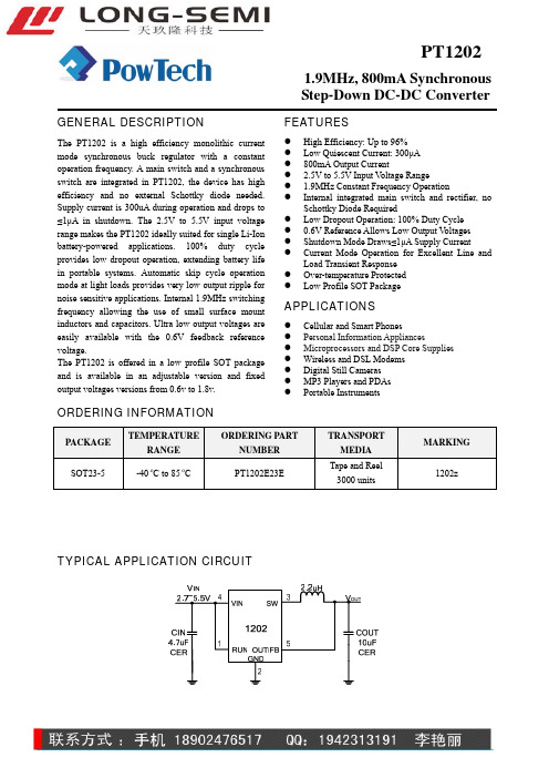
Step-Down DC-DC ConverterGENERAL DESCRIPTIONThe PT1202 is a high efficiency monolithic current mode synchronous buck regulator with a constant operation frequency. A main switch and a synchronous switch are integrated in PT1202, the device has high efficiency and no external Schottky diode needed. Supply current is 300uA during operation and drops to ≤1μA in shutdown. The 2.5V to 5.5V input voltage range makes the PT1202 ideally suited for single Li-Ion battery-powered applications. 100% duty cycle provides low dropout operation, extending battery life in portable systems. Automatic skip cycle operation mode at light loads provides very low output ripple for noise sensitive applications. Internal 1.9MHz switching frequency allowing the use of small surface mount inductors and capacitors. Ultra low output voltages are easily available with the 0.6V feedback reference voltage.The PT1202 is offered in a low profile SOT package and is available in an adjustable version and fixed output voltages versions from 0.6v to 1.8v.FEATURESz High Efficiency: Up to 96% z Low Quiescent Current: 300μA z 800mA Output Currentz 2.5V to 5.5V Input V oltage Rangez 1.9MHz Constant Frequency Operationz Internal integrated main switch and rectifier, no Schottky Diode Requiredz Low Dropout Operation: 100% Duty Cycle z 0.6V Reference Allows Low Output V oltages z Shutdown Mode Draws ≤1μA Supply Current z Current Mode Operation for Excellent Line and Load Transient Response z Over-temperature Protected zLow Profile SOT PackageAPPLICATIONSz Cellular and Smart Phonesz Personal Information Appliancesz Microprocessors and DSP Core Supplies z Wireless and DSL Modems z Digital Still Cameras z MP3 Players and PDAs zPortable InstrumentsORDERING INFORMATIONPACKAGETEMPERATURERANGEORDERING PARTNUMBERTRANSPORT MEDIAMARKING SOT23-5 -40 o C to 85 o C PT1202E23ETape and Reel 3000 units1202zTYPICAL APPLICATION CIRCUITStep-Down DC-DC ConverterPIN ASSIGNMENTPIN DESCRIPTIONSPINNAMES PIN No. DESCRIPTIONRUN 1 Chip Enable, Active with ‘H’GND 2 Chip Ground SW3Output of Internal SwitchesVIN 4 Power SupplyV FB /V OUT 5 Regulated Feedback/Output V oltageABSOLOUTE MAXIMUM RATING (Note1)SYMBOL ITEMSVALUEUNITV IN Input Supply V oltage – 0.3 to 6 V V RUN RUN Pin V oltage – 0.3 to VIN V V FB FB Pin V oltage – 0.3 to VIN VV SW SW Pin V oltage– 0.3 to (VIN + 0.3)V I SW SW Pin Source/Sink Current (DC) ±1 A I SW SW Pin Source/Sink Current (peak)±1.5AT J Junction Temperature 125 °C T OPER Operating Temperature Range – 40 to 85 °CT STG Storage Temperature Range– 65 to 150°CT SOLDER Lead Temperature (Soldering, 10 sec)300 °CθJAThermal Resister220°C/WNote1: Absolute Maximum Ratings are those values beyond which the life of the device maybe impaired.Step-Down DC-DC ConverterELECTRICAL CHARACTERISTICSTA = 25°C. VRUN=VIN = 3.6V unless otherwise specified.SYMBOL PARAMETER CONDITIONS MIN TYP MAX UNITS V FB Regulated Feedback Voltage T A=25℃0.5880.600 0.612 V ∆V FB LineRegulation V IN = 2.5V to 5.5V 0.04 0.5 %/VI FB VFB Input Bias Current 0 ±30 nAI PK PeakInductor Current V IN = 3V, V FB = 0.5V, DutyCycle < 35%1 AV LOADREG LoadRegulation 0.5 % V IN InputVoltageRange 2.5 5.5 VI S Input DC Bias CurrentActive ModeShutdownV FB = 0.5V or V OUT = 90%,I LOAD = 0AV RUN = 0V, VIN = 4.2V3000.14001µAF OSC OscillatorFrequencyV FB = 0.6V or VOUT = 100% 1.5 1.9 2.3 MHzR PFET RDS(ON) of P-ChannelFETI SW = 100mA 0.4 0.5 ΩR NFET RDS(ON) of N-Channel FET I SW = –100mA 0.35 0.45 ΩI LSW SWLeakage V RUN = 0V, V SW = 0V or 5V,V IN = 5V±0.01 ±1 µAV RUN RUNThresholdVoltage-40℃≤T A≤ 85℃0.3 1.0 1.50 V Note: The Min and Max value is guaranteed by final test or lab statistic.Step-Down DC-DC ConverterSIMPLIFIED BLOCK DIAGRAMOPERATION DESCRIPTIONThe PT1202 is a high efficiency monolithic current mode synchronous buck regulator with a constant operation frequency. Its internal integrated MOSFETs achieve high efficiency. Ultra low output voltages are easily available with the 0.6V feedback reference voltage. Internal fixed 1.9MHz switching frequency allowing the use of small surface mount inductors and capacitors. The 2.5V to 5.5V input voltage range and 800mA output current make the PT1202 ideally suited for single Li-Ion battery-powered applications.Current Mode PWM Control LoopSlope compensated current mode PWM control and cycle-by-cycle current limit provides stable operation and excellent line and load regulation. During normal operation, the internal top power MOSFET is turned on each cycle when the rising edge of the oscillator sets the RS latch, and turned off when rising edge of the PWM comparator resets the RS latch. While the top MOSFET is off, the bottom MOSFET is turned on until either the inductor current starts to reverse or the beginning of the next clock cycle. The OVDET comparator controls output transient overshoots is smaller than 8% by turning the main MOSFET off until the fault is removed.Skip-Cycles Mode OperationAt light loads, the PT1202 enters skip-cycle mode automatically. In this mode, the inductor current may reach zero or reverse on each cycle. The PWM control loop will automatically skip cycles to maintain output regulation. The bottom MOSFET is turned off by thecurrent reversal comparator, IR-CMPARATOR, and the switch voltage will ring. This is discontinuous mode operation, and is normal behavior for the switching regulator.Current Fold-Back OperationThe frequency of the oscillator is reduced to about 210 KHz when the output voltage is smaller than 50% of normal value; which ensures the inductor current has more time to decay, thereby preventing runaway. The oscillator’s frequency will progressively increase to 1.9MHz when the output voltage rises above 50%. Low-Dropout OperationWhen the input voltage deceases to the value of output voltage, the control loop remains the main MOSFET on until it reaches 100% duty cycle. The output voltage then is the input voltage minus the voltage drop across the main switch and the inductor. Caution must be exercised to ensure the heat dissipated not to exceed the maximum junction temperature of the IC because the RDSON of the main MOSFET increases and the efficiency of the converter decrease.Maximum Load CurrentThe PT1202 operates with input voltage as low as 2.5V. However, the maximum load current decreases when the input voltage deceases because of the large IR drop of the main switch and the synchronous switch. And the slope compensation reduces the peak inductor current.Step-Down DC-DC ConverterChina Resources Powtech (Shanghai) Limited Page 5PT1202_DS Rev EN_3.1TYPICAL PERFORMANCE CHARACTERISTICS(From Figure 1, TA=25 Unless Otherwise Specified)℃Efficiency vs. Input VoltageEfficiency vs. Output Current0.5110100700O utput C urrent (m A)Efficiency vs. Output Current0.500.550.600.650.700.750.800.850.900.95Output Current (mA)E f f i c i e n c yEfficiency vs. Output CurrentOutput Current (mA)Reference Voltage (V) vs. Temperature (℃) Oscillator Frequency vs. VINStep-Down DC-DC ConverterOscillator Frequency vs. Temperature (℃)Supply Current vs. Temperature (℃)Supply Current vs. Supply VoltageStart-up from ShutdownLoad StepLoad StepStep-Down DC-DC ConverterAPPLICATIONS INFORMATIONFigure 1Figure 2Setting the Output VoltageFigure 1 shows the application of fixed output voltageversion of PT1202. There are 0.6V to 5V versions areavailable. In these versions, the output voltage is set byan internal resister divider.Figure 2 shows the application of adjust version ofPT1202. In this version, the output voltage is set by anexternal resister divider according to the followingformula:⎟⎠⎞⎜⎝⎛+×=1216.0RRVVOUTInductor SelectionFor most applications, the PT1202 operates well withinductors of 1uH to 4.7uH. Low inductance values arephysically smaller but require fast switching, whichresults in efficiency loss. The inductor value can becalculated from following equation:OSCLINOUTINOUTfIVVVVL×Δ×−×=)(Table 1 list some typical surface mount inductors thatadapt to PT1202 applications.Input and Output Capacitor SelectionThe input capacitor reduces the surge current drawnfrom the input and switching noise from the device. Toprevent large voltage transients, a low ESR inputcapacitor sized for the maximum RMS current must beused. The maximum RMS capacitor current is given by:[]INOUTINOUTOMAXRMS VVVVII21)(−×≈Ceramic capacitor with X5R or C7R dielectrics arehighly recommended because of their low ESR andsmall temperature coefficients. A 4.7uF ceramiccapacitor for most applications is sufficient.The output capacitor is required to obtain small outputvoltage ripple and ensure regulation loop stability.Typically, once the ESR requirement for COUT hasbeen met, the RMS current generally far exceeds theripple current requirement. The output ripple V△OUTis determined by:81(OUTLOUT fCESRIV+×Δ≈ΔWhere f is the operating frequency, COUT is the outputcapacitor and I△L is the ripple current of inductorcurrent.Ceramic capacitors with X5R or C7R dielectrics arerecommended due to their low ESR and high currentrating. A 10uF ceramic capacitor for most applicationsis recommended for low output voltage ripple and goodloop stability.Adapter/USB ApplicationsFor USB or adapter applications, there is ±10%voltagevariation in the power supply; this device could beharmed if V IN is higher than 5.5V. To protect the device,a zener diode with 5.6Vbreak down voltage (D1 in Fig.3)is suggested to be added between V IN and GND in Table 1. Typical Surface Mount InductorsStep-Down DC-DC Converterthis kind of applications.Layout Guideline1.The power traces, including the VIN trace, theGND trace, and the SW trace should be kept short,direct and wide.2.The VFB pin should be connected directly to thefeedback resistor, and kept away from theswitching node, SW. The resistive divider R1/R2must be connected between the (+) plane of COUTand ground.3.Place the (+) plane of CIN to the VIN pin as closeas possible.4.Keep the (-) plates of CIN and COUT as close aspossible.5. A full GND plane without gap break is good forsystem noise.Step-Down DC-DC Converter PACKAGE INFORMATION5LD SOT23-5 PACKAGE OUTLINE DIMENSIONS(All dimensions in mm)。
基于sic功率器件的buck电路研究基于SIC功率器件的Buck电路研究引言:Buck电路是一种常用的降压型DC-DC转换电路,通过控制开关管的导通时间来调节输出电压。
随着功率电子器件的不断发展,基于碳化硅(SIC)功率器件的Buck电路在能效和可靠性方面具有重要的优势。
本文将对基于SIC功率器件的Buck电路进行研究,探索其在电源管理和能源转换中的应用。
一、SIC功率器件的特点SIC功率器件是一种新型的高温、高频功率器件,具有以下特点:1. 高温特性:SIC功率器件能够在高温环境下工作,具有较高的热稳定性和耐高温能力。
2. 高频特性:SIC功率器件具有较高的开关速度和频率响应,适用于高频应用。
3. 低导通电阻:SIC功率器件的导通电阻较低,能够实现更高的功率密度和能效。
4. 高击穿电压:SIC功率器件具有较高的击穿电压,能够在高电压环境下工作。
二、Buck电路原理Buck电路是一种降压型DC-DC转换电路,通过控制开关管的导通时间来调节输出电压。
其原理如下:1. 当开关管导通时,电感储能,输出电压与输入电压相等。
2. 当开关管关断时,电感释放能量,通过二极管供电,输出电压小于输入电压。
3. 通过调节开关管的导通时间,可以调节输出电压的大小。
三、基于SIC功率器件的Buck电路设计基于SIC功率器件的Buck电路设计具有以下步骤:1. 确定输入电压范围和输出电压需求。
2. 根据电流需求选择合适的SIC功率器件。
3. 根据功率需求选择合适的电感和电容。
4. 设计开关管的控制电路,实现对输出电压的调节。
5. 进行电路仿真和实验验证,优化电路参数。
四、基于SIC功率器件的Buck电路应用基于SIC功率器件的Buck电路在电源管理和能源转换中具有广泛的应用,主要包括以下方面:1. 电动车充电器:SIC功率器件能够在高温环境下工作,具有较高的能效和可靠性,适用于电动车充电器的设计。
2. 太阳能逆变器:SIC功率器件具有较高的开关频率响应,能够实现太阳能逆变器的高效转换。
DESCRIPTIONThe EUP3485 is a 500KHz fixed frequency synchronous current mode buck regulator. The device integrates both 110m Ω high-side switch and 30m Ω low-side switch that provide 4A of continuous load current over a wide operating input voltage of 4.5V to 18V . The internal synchronous power switch increases efficiency and eliminates the need for an external Schottky diode. Current mode control provides fast transient response and cycle-by-cycle current limit.The EUP3485 features short circuit and thermal protection circuits to increase system reliability. In shutdown mode, the supply current drops below 1µA. The EUP3485 is available in SOP-8 package with an exposed pad.Typical Application CircuitFEATURES4A Continuous Output Current 100ns Minimum On TimeIntegrated 110m Ω High-side Switch Integrated 30m Ω Low-side SwitchWide 4.5V to 18V Operating Input Range Output Adjustable from 0.8VFixed 500KHz Switching FrequencySync from 300KHz to 2MHz External Clock Internal Compensation Internal Soft-Start<1µA Shutdown CurrentThermal Shutdown and Over current Protection Input Under V oltage Lockout Available in SOP-8 (EP) PackageRoHS Compliant and 100% Lead(Pb)-Free Halogen-FreeAPPLICATIONSDistributed Power Systems Networking SystemsNotebook Systems and I/O Power Flat Panel Television and Monitors Personal Video RecordersDigital Set Top BoxesFigure 1.Pin ConfigurationsPackage Type Pin ConfigurationsSOP-8 (EP)Pin DescriptionNumber Pin NameDescription1 IN Power Input. IN supplies the power to the IC, as well as the step-down converter switches. Drive IN with a 4.5V to 18V power source. Bypass IN to GND with a suitably large capacitor to eliminate noise on the input to the IC. See Input Capacitor.2,3 SW Power Switching Output. SW is the switching node that supplies power to the output. Connect the output LC filter from SW to the output load.4 BST High-Side Gate Drive Boost Input. BST supplies the drive for the high-side N-Channel DMOS switch. Connect a 0.01µF or greater capacitor from SW to BST to power the high side switch.5 EN/SYNC Enable Input. EN is a digital input that turns the regulator on or off. Drive EN high to turn on the regulator; low to turn it off. Attach to IN with a 100kΩ pull up resistor for automatic startup. External clock can be applied to EN pin for changing switching frequency.6 FB Feedback Input. FB senses the output voltage and regulates it. Drive FB with a resistive voltage divider connected to it from the output voltage. To prevent current limit run away during a short circuit fault condition the frequency fold-back comparator lowers the oscillator frequency when the FB voltage is below 600mV.7 VCC Bias Supply. Decouple with 0.1µF or greater capacitor.89(Exposed Pad) GNDSystem Ground. This pin is the reference ground of the regulated output voltage. Forthis reason care must be taken in PCB layout. Suggested to be connected to GNDwith copper and vias.Ordering InformationOrder Number Package Type Marking Operating Temperature RangeEUP3485WIR1SOP-8 (EP)xxxxxP3485-40 °C to +85°CEUP3485□□□□Lead Free Code1: Lead Free, Halogen Free 0: LeadPackingR: Tape & ReelOperating temperature rangeI: Industry StandardPackage TypeW: SOP (EP)Block DiagramFigure 3.Absolute Maximum Ratings (1)Supply V oltage (V IN) -------------------------------------------------------- -0.3V to +20VEN Voltage (V EN) -------------------------------------------------------- -0.3V to +6VSwitch V oltages (V SW) ------------------------------------------------------ -1V to V IN +0.3VBootstrap V oltage (V BST) ---------------------------------------------- V SW -0.3V to V SW +6VAll Other Pins ---------------------------------------------------------------------- -0.3V to +6VJunction Temperature --------------------------------------------------------------------150°CLead Temperature ------------------------------------------------------------------------260°CStorage Temperature ---------------------------------------------------------65°C to 150°CThermal Resistance: θJA (SOP-8_EP) -------------------------------------------------- 60°C /WESD Ratings: Human Body Mode --------------------------------------------------------- ±2kV Recommend Operating Conditions (2)Input Voltage (V IN) --------------------------------------------------------------- 4.5V to 18VOperating Temperature Range ----------------------------------------------- -40°C to +85°C Note (1): Stress beyond those listed under “Absolute Maximum Ratings” may damage the device.Note (2): The device is not guaranteed to function outside the recommended operating conditions.Electrical CharacteristicsV IN=12V ,T A=+25°C, unless otherwise specified.EUP3485 Symbol Parameter ConditionsMin. Typ. Max.UnitI IN Supply Current(Shutdown) V EN=0V 0.1 µAI IN Supply Current(Quiescent) V EN=2V, V FB=1V 0.9 mAR DSONH High-side Switch OnResistance110 mΩR DSONL Low-side Switch On Resistance 30 mΩSW LKG Switch Leakage V EN=0V, V SW=0V or 12V 0 10 µA I LIMIT Current Limit 4.6 6 A F SW Oscillator Frequency V FB=0.75V 350 500 650 KHz F FB Fold-back Frequency V FB=300mV 0.25 f sw D MAX Maximum Duty Cycle V FB=700mV 85 90 % F SYNC Sync Frequency Range 0.3 2 MHz V FB Feedback V oltage 788 808 828 mV I FB Feedback Current V FB=800mV 10 50 nA V ENL EN/SYNC Input Low V oltage 0.4 V V ENH EN/SYNC Input High V oltage 2 VV EN=2V 2I EN EN Input CurrentV EN=0V 0µA EN Td-off EN Turn Off Delay 8 µsV UVLO V IN Under Voltage LockoutThreshold Rising3.84.0 4.2 VV UVLO HYS V IN Under Voltage LockoutThreshold Hysteresis0.9 VV CC VCC Regulator 5 V VCC Load Regulation I CC=5mA 5 % T SD Thermal Shutdown 170 °C T SDHYS Thermal Shutdown Hysteresis 20 °CTypical Performance CharacteristicsC IN = 22µF, C OUT= 47µF, L= 2.2µH, T A=+25°C,unless otherwise noted.C IN = 22µF, C OUT= 47µF, L= 2.2µH, T A=+25°C,unless otherwise noted.C IN = 22µF, C OUT = 47µF, L= 2.2µH, TA=+25°C,unless otherwise noted.C IN = 22µF, C OUT= 47µF, L= 2.2µH, T A=+25°C,unless otherwise noted.Functional DescriptionThe EUP3485 regulates input voltages from 4.5V to 18V down to an output voltage as low as 0.8V , and supplies up to 4A of load current.The EUP3485 uses a fixed frequency, peak current control mode to regulate the output voltage. A PWM cycle is initiated by the internal clock. The integrated high-side power MOSFET is turned on and remains on until its current reaches the value set by the COMP voltage. When the power switch is off, it remains off until the next clock cycle starts. If, in 90% of one PWM period, the current in the power MOSFET does not reach the COMP set current value, the power MOSFET will be forced to turn off.Application InformationSetting the Output VoltageThe output voltage is set using a resistive voltage divider connected from the output voltage to FB (see Figure 1.). The voltage divider divides the output voltage down to the feedback voltage by the ratio:Thus the output voltage is:The feedback resistor R 1 also sets the feedback loop bandwidth with the internal compensation capacitor. Choose R 1 for optimal transient response. R 2 is then given by:Table 1. Recommended Divider Resistor Selection:V OUT (V) R 1 (k Ω) R 2 (k Ω) 1.2 60.4 124 1.8 60.4 48.7 2.5 60.4 28.7 3.3 100 32.4 5 150 28.7 InductorThe inductor is required to supply constant current to the load while being driven by the switched input voltage. A larger value inductor will result in less ripple current that will in turn results in lower output ripple voltage. However, the larger value inductor will have a larger physical size, higher series resistance, and/or lower saturation current. A good rule for determining inductance is to allow the peak-to-peak ripple current to be approximately 30% of the maximum switch current limit. Also, make surethat the peak inductor current is below the maximum switch current limit.The inductance value can be calculated by:V V1(I f V L INOUT L S OUT −×∆×=Where V OUT is the output voltage, V IN is the inputvoltage, f S is the switching frequency, and ∆I L is the peak-to-peak inductor ripple current.Choose an inductor that will not saturate under the maximum inductor peak current, calculated by:V V1(L f 2V I I INOUT S OUT LOAD LP −×××+=Where I LOAD is the load current.The choice of which style inductor to use mainly depends on the price vs. size requirements and any EMI constraints.Optional Schottky DiodeDuring the transition between the high-side switch and low-side switch, the body diode of the low-side power MOSFET conducts the inductor current. The forward voltage of this body diode is high. An optional Schottky diode may be paralleled between the SW pin and GND pin to improve overall efficiency.Input CapacitorThe input current to the step-down converter is discontinuous, therefore a capacitor is required to supply the AC current while maintaining the DC input voltage. Use low ESR capacitors for the best performance. Ceramic capacitors are preferred, but tantalum or low-ESR electrolytic capacitors will also suffice. Choose X5R or X7R dielectrics when using ceramic capacitors.Since the input capacitor (C IN ) absorbs the input switching current, it requires an adequate ripple current rating. The RMS current in the input capacitor can be estimated by:)V V1(V V I I INOUT IN OUT LOAD CIN −××= The worst-case condition occurs at V IN = 2V OUT ,where IC IN = I LOAD /2. For simplification, use an input capacitor with a RMS current rating greater than half of the maximum load current.The input capacitor can be electrolytic, tantalum or ceramic. When using electrolytic or tantalum capacitors, a small high quality ceramic capacitor, i.e. 0.1µF, should be placed as close to the IC as possible. When using ceramic capacitors, make sure that they have enough capacitance to provide sufficient charge to prevent excessive voltage ripple at input. The input voltage ripple for low ESR capacitors can be212OUTFB R +R R V =V 1V 808.0V R R OUT12−=221OUT R R R 808.0V +×=estimated by:)V V 1(V V f C I V INUT O IN UT O S IN OADL IN −×××=∆where C IN is the input capacitor value. Forsimplification, choose the input capacitor whose RMS current rating greater than half of the maximum load current.Output CapacitorThe output capacitor (C OUT ) is required to maintain the DC output voltage. Ceramic, tantalum, or low ESR electrolytic capacitors are recommended. Low ESR capacitors are preferred to keep the output voltage ripple low. The output voltage ripple can be estimated by:Where C OUT is the output capacitance value and R ESR is the equivalent series resistance (ESR) value of the output capacitor.When using ceramic capacitors, the impedance at the switching frequency is dominated by the capacitance which is the main cause for the output voltage ripple. For simplification, the output voltage ripple can be estimated by:V V 1(C L f 8V V IN OUTOUT2S OUT OUT −××××=∆ When using tantalum or electrolytic capacitors, theESR dominates the impedance at the switching frequency. For simplification, the output ripple can be approximated to:ESR INOUT S OUT OUT R )V V1(L f V V ×−××=∆ The characteristics of the output capacitor also affectthe stability of the regulation system. The EUP3485 can be optimized for a wide range of capacitance and ESR values. PCB Layout GuidePCB layout is very important to achieve stable operation. Please follow these guidelines.1) Keep the connection of input ground and GND pinas short and wide as possible.2) Keep the connection of anode of input capacitorand IN pin as short and wide as possible.3) Ensure all feedback connections are short anddirect. Place the feedback resistors and compensation components as close to the chip as possible.4) Route SW away from sensitive analog areas suchas FB.5) Connect IN, SW, and especially GND respectivelyto a large copper area to cool the chip to improve thermal performance and long-term reliability.C f 81R ()V V 1(L f V V OUT S ESR IN OUT S OUT OUT ××+×−××=∆EUP3485DS3485 Ver1.1 Nov. 201011 Packaging InformationSOP-8 (EP)MILLIMETERS INCHES SYMBOLSMIN. MAX. MIN. MAX. A 1.35 1.75 0.053 0.069 A1 0.100.250.0040.010D 4.90 0.193 E1 3.90 0.153 D1 2.97 0.117 E2 2.180.086E 5.80 6.20 0.228 0.244 L 0.40 1.27 0.016 0.050 b 0.310.510.0120.020 e1.270.050。
上海南芯半导体科技有限公司SC8804 DATASHEETSOUTHCHIP CONFIDENTIAL, DISCLOSURE UNDER NDA SC8804 高效率, 同步, 升压充电降压放电双向控制器Copyright © 2016, 上海南芯半导体科技有限公司具体应用信息请联系application@SC8804 DATASHEETSOUTHCHIP CONFIDENTIAL, DISCLOSURE UNDER NDA 上海南芯半导体科技有限公司5应用电路图DIR = Low, 充电(charging)DIR = High, 反向放电(discharging)2具体应用信息请联系application@ Copyright © 2016, Southchip Semiconductor Technology (Shanghai) Co., Ltd.SC8804 DATASHEET上海南芯半导体科技有限公司SOUTHCHIP CONFIDENTIAL, DISCLOSURE UNDER NDACopyright © 2016, Southchip Semiconductor Technology (Shanghai) Co., Ltd. 具体应用信息请联系application@ 36 管脚设置及功能简介C P _HC P _LN CV B U SS N S 1N P G N DN CS N S 1PSC8804 DATASHEETSOUTHCHIP CONFIDENTIAL, DISCLOSURE UNDER NDA 上海南芯半导体科技有限公司4具体应用信息请联系application@ Copyright © 2016, Southchip Semiconductor Technology (Shanghai) Co., Ltd.SC8804 DATASHEET 上海南芯半导体科技有限公司SOUTHCHIP CONFIDENTIAL, DISCLOSURE UNDER NDACopyright © 2016, Southchip Semiconductor Technology (Shanghai) Co., Ltd. 具体应用信息请联系application@ 5SC8804 DATASHEETSOUTHCHIP CONFIDENTIAL, DISCLOSURE UNDER NDA 上海南芯半导体科技有限公司7电气规格7.1绝对最大耐压在通风温度范围之内(除非另外标注)(1)6具体应用信息请联系application@ Copyright © 2016, Southchip Semiconductor Technology (Shanghai) Co., Ltd.SC8804 DATASHEET 上海南芯半导体科技有限公司SOUTHCHIP CONFIDENTIAL, DISCLOSURE UNDER NDACopyright © 2016, Southchip Semiconductor Technology (Shanghai) Co., Ltd. 具体应用信息请联系application@ 7SC8804 DATASHEETSOUTHCHIP CONFIDENTIAL, DISCLOSURE UNDER NDA 上海南芯半导体科技有限公司7.4电气性能T J= 25°C and V BUS = 12V, V BAT = 5V, R SS1 = R SS2= 1kΩ unless otherwise noted.8具体应用信息请联系application@ Copyright © 2016, Southchip Semiconductor Technology (Shanghai) Co., Ltd.SC8804 DATASHEET 上海南芯半导体科技有限公司SOUTHCHIP CONFIDENTIAL, DISCLOSURE UNDER NDACopyright © 2016, Southchip Semiconductor Technology (Shanghai) Co., Ltd. 具体应用信息请联系application@ 9SC8804 DATASHEETSOUTHCHIP CONFIDENTIAL, DISCLOSURE UNDER NDA 上海南芯半导体科技有限公司10具体应用信息请联系application@ Copyright © 2016, Southchip Semiconductor Technology (Shanghai) Co., Ltd.8和截止电压的对应关系如下表所示:表格 1 CSEL 电阻设定充电截止电压SC8804通过R SNS1和R SNS2分别检测VBUS 端和VBAT 端充电电流,如下图所示:电池端充电电流RVRRR1)R SNSx需连接在MOS管和输入/输出电容之间2)R SS1/R SS1’为一对电阻对,阻值需相等,同理,R SS2/R SS2’也需相等,典型值为1 kΩ若需要调整R SNSx的阻值,则对应的R SSx/R SSx’阻值也需要),1) 2) 3) 4)SC8804支持充电自适应功能。